
Rutan Quickie
Background
Hauler/Brengun was founded in 1999 and produces scale plastic kits, resin kits and accessories, photo-etched details for kits and other accessories. This kit of the Rutan Quickie is offered in two different scales: 1/72 and 1/48.
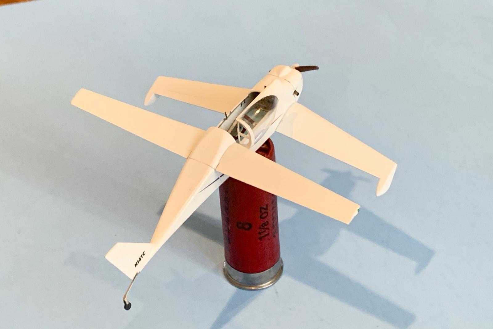
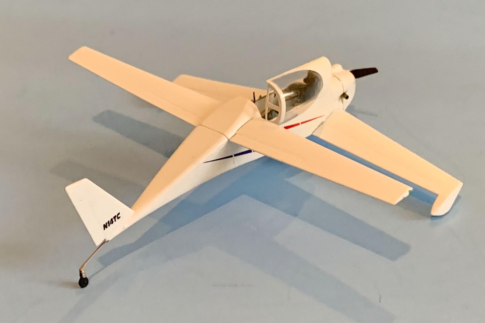
The Rutan Quickie is a lightweight single-seat taildragger aircraft of composite construction, configured with tandem wings. The Quickie was primarily designed by Burt Rutan in 1977 as a low-powered, highly efficient kit-plane. After the first flights, Tom Jewett and Gene Sheehan continued development of the Quickie to market it for home-build projects. Over 350 kits were produced between 1978 and 1980, with ultimately some 1,000 kits being sold. The recommended engine is a Onan four-stroke piston engine delivering 18 hp, although since it was a kit plane, there was considerable variability. Its tandem wing design has one anhedral forward wing and one slightly larger dihedral rear wing. The forward wing has full-span control surfaces and is thus similar to a canard wing, but is considerably larger. The aircraft has unusual landing gear, with the main wheels located at the tips of the forward wing.
The Kit
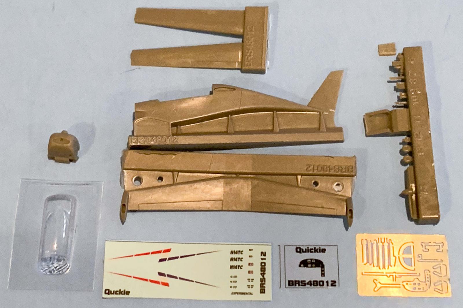
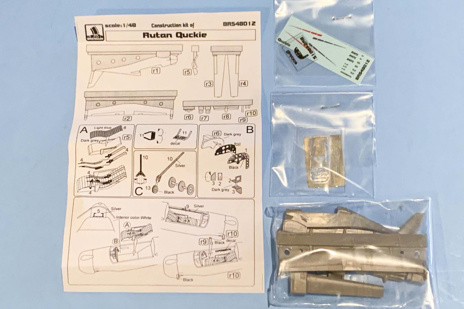
The Brengun 1/48 Rutan Quickie consists of 15 pieces of gray resin, a vacuform canopy, instrument panel film, and a photoetch fret with 14 pieces. Since there was a lot of variability in home-builts, there are several options, so not all parts may be used. A quick scan of the internet will display many more options that are available as it appears the basic platform displays different engines, exhausts, cockpits, and tailwheels. At first glance the resin looks well done and displays very nice detail, with only a few tiny bubbles on the belly of the airframe. There are decals for one aircraft, but a quick internet check will display many different schemes. Most are primarily white, since paint does add weight to the aircraft.
Construction
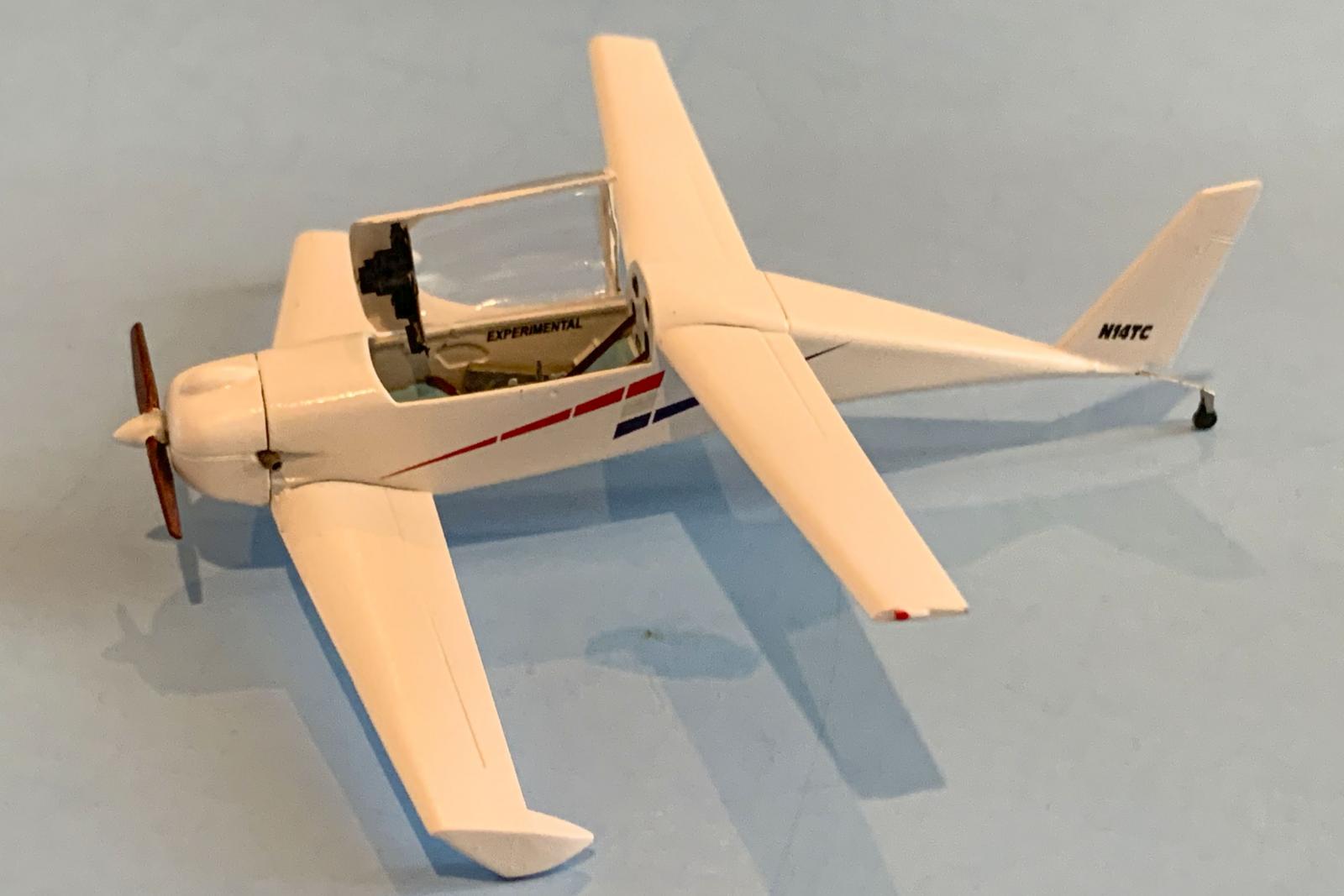
Your first task will be to identify what machine you wish to build. The kit provides decals for N14TC which represent Terry Crouch’s 1994 Quickie (see EAA Chapter 75). I ended up using that scheme, but with a few differences. Make sure that you bathe the resin parts in soap and water for at least 20 seconds to meet CDC standards. This effort will be important the make sure the resin is free of any mold-release (ask me how I know). I also would recommend carefully using some painter’s poly-fiber scouring pads to clean up the photo-etch, especially the rotor blades. I used Scotch-Brite Light Duty Cleansing Pads (White) and they worked perfectly.
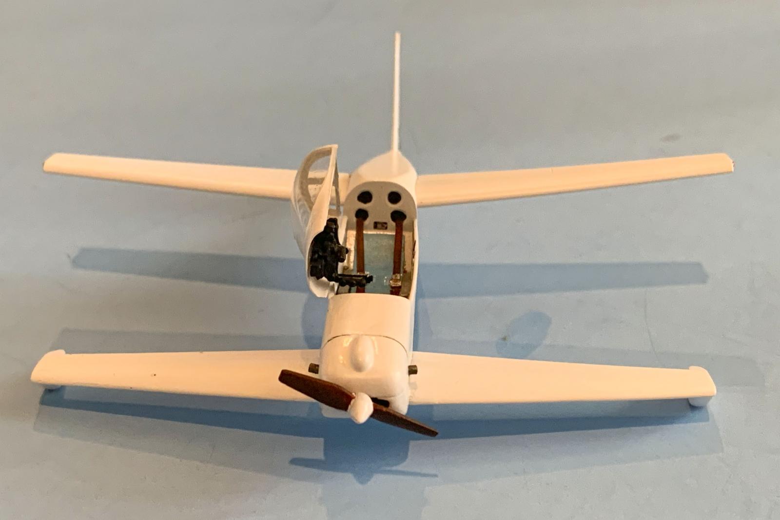
I used a fine tooth razor saw to separate the nose, wings and fuselage from their pour blocks. I then carefully sanded to obtain an optimum fit. Brengun did an excellent job here as the fuselage and wings mated easily. What you will need to pay attention to is that the lower fuselage revealed some air bubbles when cleaning up from the pour block (see photo). Your results may vary depending on the pour, so be careful. I used baking soda to fill the air bubbles and then applied super glue. I waited about five minutes before judicious sanding with a sanding stick to get the lower fuselage nice and smooth. I used a series of carbide drills to drill the exhaust ports a bit deeper.
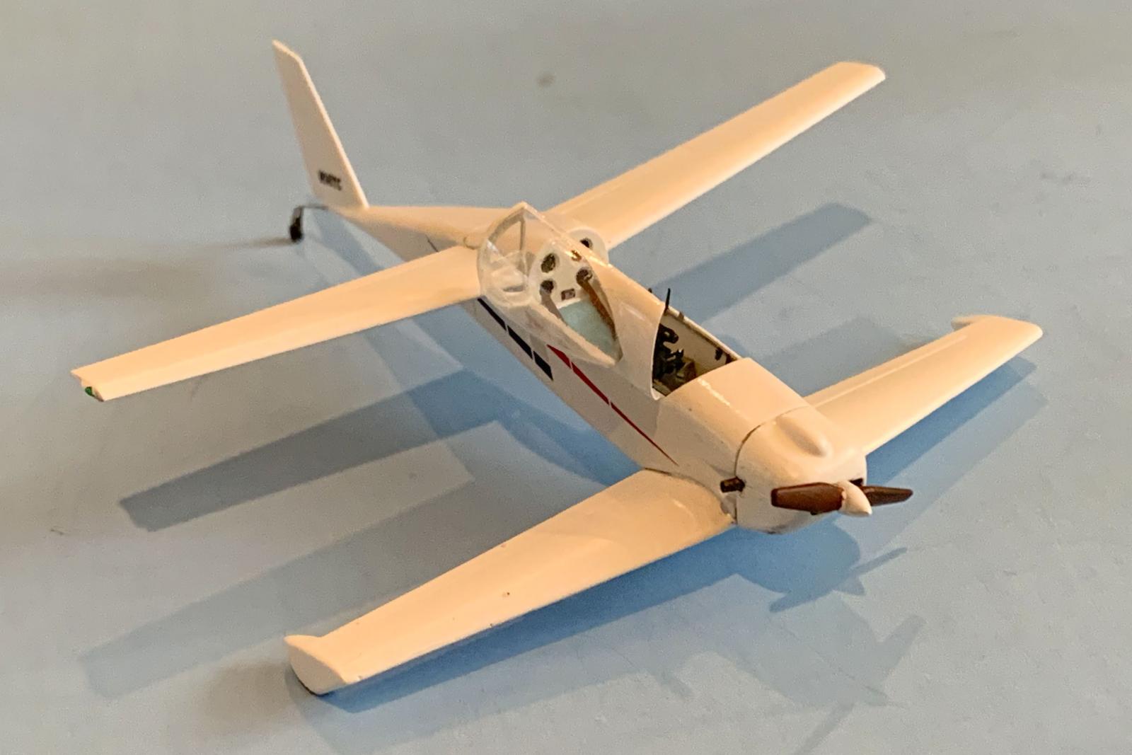
Getting the nose to fit properly was also interesting since the proper angle relative to the fuselage is rather distinctive. You want to sand and test fit often to make sure you get just the right fit. Once I got the lower wing and nose installed, I attached the upper wings. I downloaded a 3-D view from the internet and sized it to get the correct dihedral. I then used Lego blocks to assure that everything was aligned with the fuselage and lower wing. Next up, I brushed on Future to the vacuform canopy and set aside to dry thoroughly.
I started on the cockpit next. I will note that the instructions don’t match well with the parts provided. Step A depicts a Part 8 to be attached to the resin seat (R5), but Part 8 is not included. From what I can tell, Part 8 was probably a photoetched part at one time, but now its detail has been incorporated into the resin seat (R5). I painted up the resin seat and seat belts next and attached the lap belts. I superglued the two shoulder straps together and allowed them to dry. The next step for the cockpit is to place the photoetch rudder pedals into the forward fuselage. Once you get ready to finish the cockpit, superglue the seat into the fuselage being careful to line up the rear of the seat with the rear of the cockpit. The rear of the straps are then superglued to the lower two ports at the back of the cockpit. Once dried, I carefully bent the shoulder straps down to fit the contours of the seat.
Step B depicts the assembly of the instrument panel, comprised of the photo-etched instrument panel, instrument film, and the resin backing that depicts the rear of the instrument panel. For those that are daring, one can place wire leads into the back of each instrument housing and bind them into a wire bundle that will snake its way under the upper forward fuselage. This detail would be quite evident with the canopy open since the instrument panel is attached to the canopy, not the fuselage frame. (Note: the instructions depict the instrument panel attached to the fuselage frame, but I was not able to locate any photographs on the internet that depicted it this way. All pictures that I found showed the instrument panel attached to the front canopy so that when the canopy is opened, the instrument panel is out of the way. My guess this is to ease entry into the super small cockpit.) Another instruction issue is also apparent in Step B where two photoetch parts parts (2 and 3) are not actually on the photoetch sheet. This probably fine as this assembly is not shown elsewhere in the instructions.
Step C shows the tail wheel assembly. I folded the photoetched part easily using thin flat jaw pliers as shown on the drawing. The actual tailwheel includes a tailwheel yoke already on the tailwheel, making it easy to slide the yoke into the folded photoetch tail wheel flat spring. There really is not an opening at the rear of the fuselage to attach this assembly so you will need to create one. I waited till nearly the end of the build as I was afraid that the tailwheel assembly wouldn’t hold the weight of the model (somewhat justified). I used a razor saw to create a horizontal cut at the rear of the fuselage just under the vertical fin and was able to slide the tailwheel into this cut. Those of you craving more detail, there is actually more detail that you can add. The small bulges on the rear of the fuselage depict where the tailwheel steering wires would come out to connect to a pivot on the tailwheel assembly. Simply use a micro drill bit to open them up and insert the steering wires and connect them to the tailwheel yoke. Above Instruction “C” are directions to fold the booster tabs. They folded very easily, but attaching them to the lower wing ailerons was another story since the attachment points was extremely minimal. These are apparent on photographs of N14TC, but are not present in most of the Quickie photographs I saw. These tabs have to be set before flight and essentially act as power steering for the ailerons.
The next step (unlabeled) at the bottom of the page shows the location of the rudder pedals, the seat assembly, the instrument panel (see notes above in Step B about where the instrument panel actually goes. Parts R10 appear to be the two exhausts, although as seen on the resin pour bock there is only one exhaust provided. I decided to use a thin wall brass tubing to replicate the exhausts. The brass exhausts were cut to length with a razor saw and inserted into the hole previously drilled out on both sides of the nose cowling. The remaining part show in this step I presume to be a control stick, but what is depicted in the instructions does not resemble what is provided on the resin block for R9. I used a plastic rod to replicate a control stick. The remaining two parts on the resin block, R7 and R8, are not mentioned in the instructions, and I am not sure what they represent. Photoetch Part 9 appears to be the canopy locking mechanism. It was superglued in with no problem, although I continued to try to knock it off at every opportunity. Miraculously, superglue secured it well enough to stay in place.
The second page of the instructions depict adding the wings to the fuselage, adding the propeller, the booster tabs, the main wheels, and the tail wheel assembly. Due to concerns over the fragility of the tail wheel assembly, I waited till the very end of the build to add it to the airframe. This section also shows the installation of the rear frame of the canopy. I will point out that with the canopy propped open, this is no issued, but for a closed canopy you will have to make some modifications. The photoetched Part 7 is to wide to show the canopy closed. I don’t have a good answer for this problem, which is why I built the Quickie with the canopy open, where it is not an issue. The bottom of this page provides exterior decal placement information. One part that is on the photoetch sheet that is not in the instructions is PE Part 6, which I took to be the canopy strut to hold the canopy open. It worked quite well as I was finishing up before disappearing into the carpet. I am sure I will find it at some point, but it remains on the loose.
Painting & Decals
Once I had assembled the basic airframe, I primed the model with Tamiya Surfacer Primer (light grey) to resolve the resin bubble issues that appeared. Once satisfied, I sprayed the model with Vallejo Model Air White (71-001). I used Tamiya masking tape to mask off the canopy after giving the Future a chance to dry for a week and sprayed the canopy exterior as well. I primed the photoetch sheet and remaining resin pieces still on their pour stubs with Tamiya Surface Primer (light grey). The pilot’s seat was painted Vallejo Model Color 70-961 Sky Blue with Vallejo Metal Color 77-706 White Aluminum arm rests. The rudder pedals and tail wheel spring were painted with Vallejo Metal Color 77-712 Steel. The seat belts were painted Vallejo Model Air 71-271 German Red Brown accompanied with Vallejo Metal Color 77-706 White Aluminum for the buckles. The Canopy locking linkage was painted a combination of Vallejo Metal Color 77-724 Silver and 77-713 Jet Exhaust. The exhausts were painted with Jet Exhaust and then highlighted with Tamiya Panel Line Accent Color Brown. The tires were painted Vallejo Model Air 71-052 German Grey as was the resin instrument panel housings and the photoetch instrument panel. I then painted the front of the resin instrument panel housing with Vallejo Metal Color 77-706 White Aluminum to highlight the instrument film that was trapped between the housing and panel. The propeller blades were painted a combination of Vallejo Model Air 71-027 Light Brown and 71-042 Dark Brown. I also used Vallejo Model Color 70-935 Transparent Orange, but ended up doing a Dark Brown wash afterwards as the transparent orange just gave the blades a really odd look. They really turned out darker than I was looking for, but I’ll play with that later on.
Decaling was up next. I brushed on Future everywhere where decals were going to go and let dry for two days. I mistakenly started out with the “Z stripe” before realizing that cutting as close to the decal as possible was necessary due to the clear carrier film. The rest of the decals got cut very close to the actual decal and things worked out well. You do get some extra decals with three “N14TC”, three “NO STEP”, and two data plates (two in 1/48 and two in 1/72. The “EXPERIMENTAL” decal fit very nicely inside the cockpit. The front cowling ‘engine intakes’ also comes with an extra, which came in handy when the first one disappeared while drying. Using the spare decal I immediately secured it with a coat of Future to keep it in place. The first “Z stripe” decal I was able to successfully sand the edges of the excess film. Accompanied with a coat of Future, it blends in well.
Overall Evaluation
Even at a hair over 4" in length, this is a nice multi-media kit. I’ve included a 12-gauge shell to give you an idea of the size of this kit. The only real gotcha was the rear canopy photoetch frame, everything else was of my own screw-ups; and again, If you leave the canopy open its no issue. I would recommend that one be sure to have the appropriate tools on hand. This would include a razor saw and small tweezers. I'm planning on buying this kit out of my own pocket to do it again, in different markings. While this may not be a kit for the novice due to the small photoetch parts, it would be fine for those with any experience under the belt. I mentioned earlier that this kit is also available in 1/72 if you want something really small.
My thanks to Hauler-Brengun and IPMS/USA for the chance to review this great kit.
Highly Recommended !


Reviewer Bio
Frank Landrus

Frank retired from the Ophthalmic industry with over thirty-six years of Research and Development experience. Frank's first model kit was a 1959 Hawk 1/72 US Marines Vought AU-1 Corsair and has been building models for over sixty years. Frank's first encounter with IPMS was attending a North Central Texas ScaleFest show in 1984. Frank soon became more involved in Make-N-Take activities and became the IPMS Western Coordinator for Make-N-Takes [West of the Mississippi River]. Make-N-Takes quickly became a local model contest and airshow staple reaching a high of reaching over 1,300 children before the COVID shutdown. Frank has volunteered to assist in contest judging since 1985 and is currently the Nationals Head Figure Judge until he is dead or they find someone better.
Comments
Add new comment
This site is protected by reCAPTCHA and the Google Privacy Policy and Terms of Service apply.
Similar Reviews