
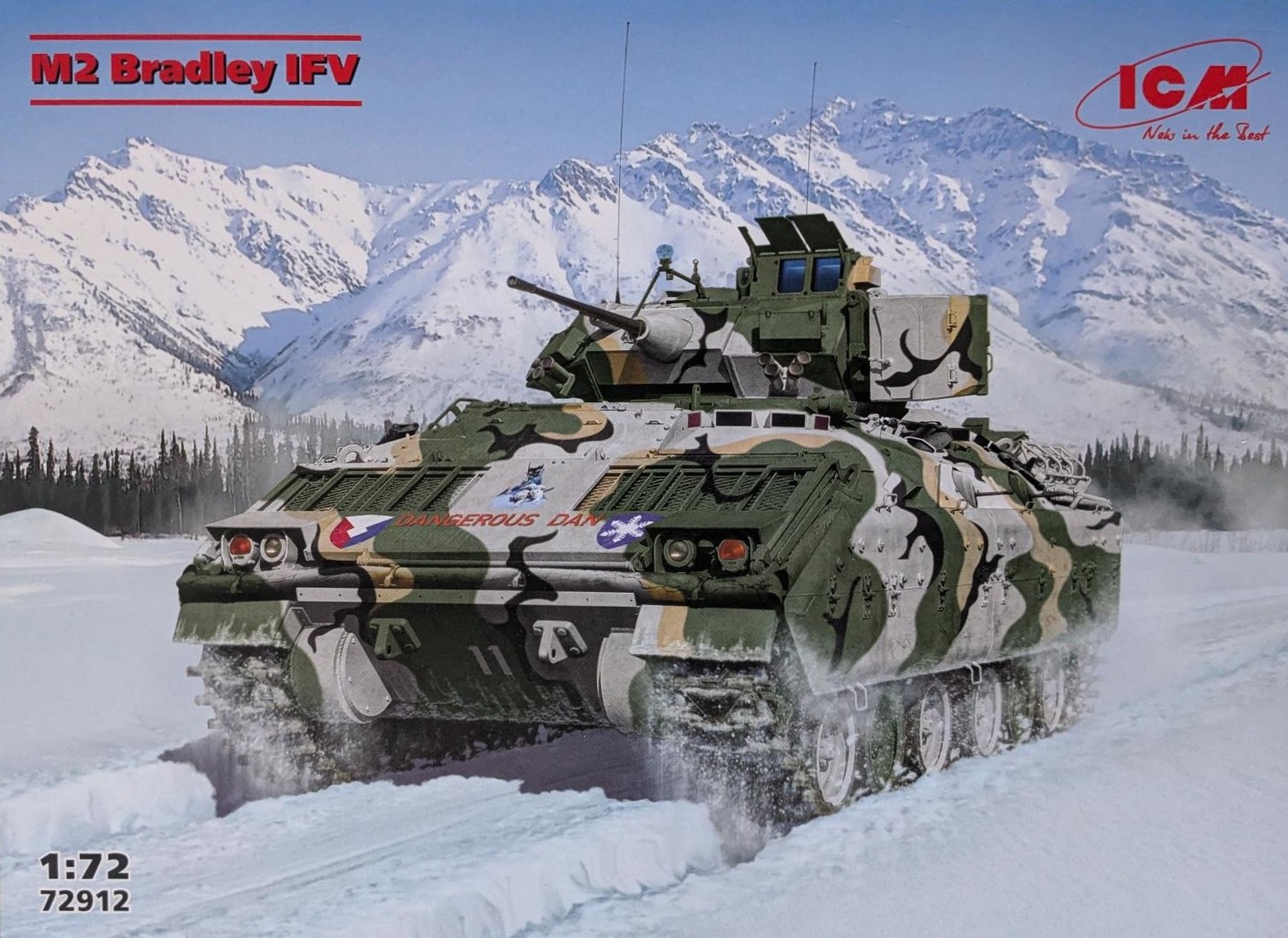
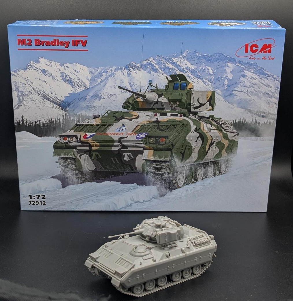
M2 Bradley IFV
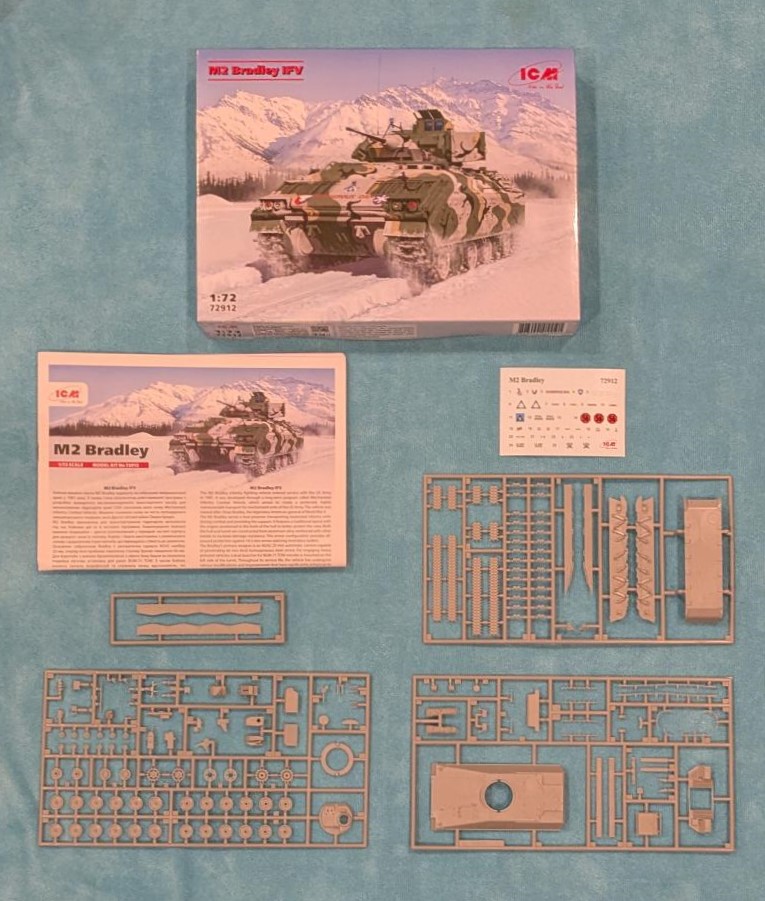
Upon opening the cover, there is a reinforced white inner box that does a good job of protecting the kit’s seven gray plastic sprues, and decal sheet (I recently heard on the Beyond the Box Art podcast that ICM’s boxes are designed to withstand the rigors of delivery services, and this box definitely meets that standard). The instructions span 12 pages and cover 38 steps. The downloadable instructions are also available separately online at the ICM website. Take care with small pieces (grab handles, etc) as the plastic is fragile and can break when removed from the sprue gates.
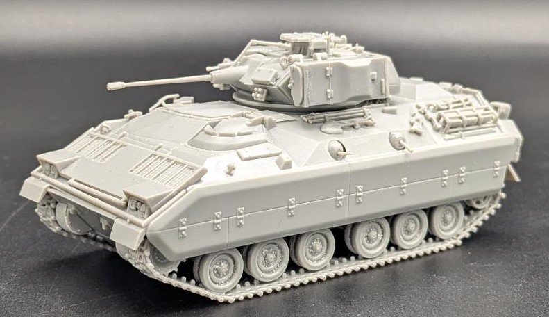
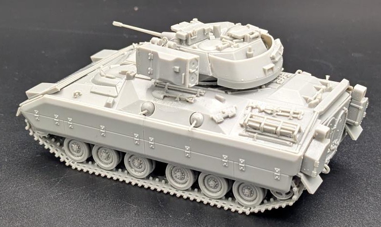
This is a former Revell M2/M3 Bradley kit (No. 03143) that was first issued in 2005 (with the hull tub dating to 2001 Kit No. 03124). The ICM boxing uses new decals and keeps it relevant for modern armor builders. The inclusion of decals for four colorful Bradleys, where only one is overall green, is nice and really highlights the M2 Bradley’s early career.
There are minor notes that are identified here by their instruction step:
Step 06: The link and length tracks assemble well if you take your time. Of note, the top run of the track is not visible once the side skirts are installed.
Step 10: Watch the orientation of Part No. 23 to ensure the tow cable is facing outside (ask me how I know).
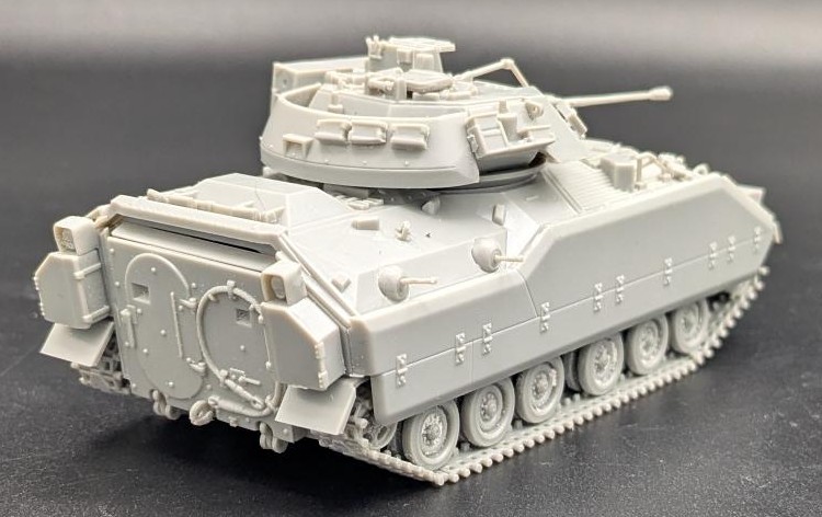
Step 11: The main troop ramp (Step 10) is held by hinges (2 x Parts Nos. 25 and 26) that require them to be glued together, but not to the ramp. This is superfluous as there is no interior. Save yourself some pain and glue the ramp in place on the hull, then glue the hinges. While not workable, they are solid and a lot easier to assemble.
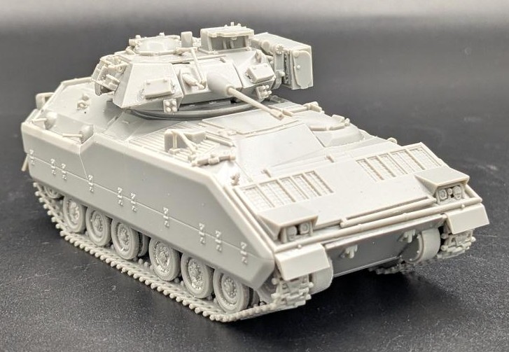
Step 15: There are four-gun barrels (Part No. 110) which fit into the ball mounting (Part No. 109). The barrels are fiddly and will most likely break off. The barrels have to be installed at this step as the top and bottom hulls are joined six steps later and the interior of the ball mounts won’t be accessible. In hindsight, I would install the ball mounts into the hull (Part No. 32) and leave the gun barrels out. After the model is painted and weathered, it would be easier to snip the barrel stops and insert the barrels into the ball mounts. These gun ports were eliminated in later production models.
Step 19: The spare ammo cans (Part No. 44) are to be mounted directly onto the rear hull. Save yourself frustration and install Part No. 44 into the storage rack (Part No. 115, Step 25), before installing the rack onto the hull.
Step 23: Exercise caution removing Part No. 111 from the sprue gate and sanding the nubs as this piece is very fragile. Good thing is that it can be glued onto the glacis in segments and look the same as if it had been installed intact.
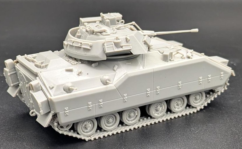
Step 27: The connection point for mantlet (Part No. 64) to barrel elevation (Part No. 61) is very fiddly and temperamental. Refer to photographs to get the correct orientation and depth, trim the connection point and glue for strength.
Step 29: Take care removing and cleaning up Part No. 76 (ring sight).
Step 36: The TOW launcher provides the option of stowed (36.a) or firing position (36.b). Refer to Step 37 for which option preferred.
There are four marking options for this kit:
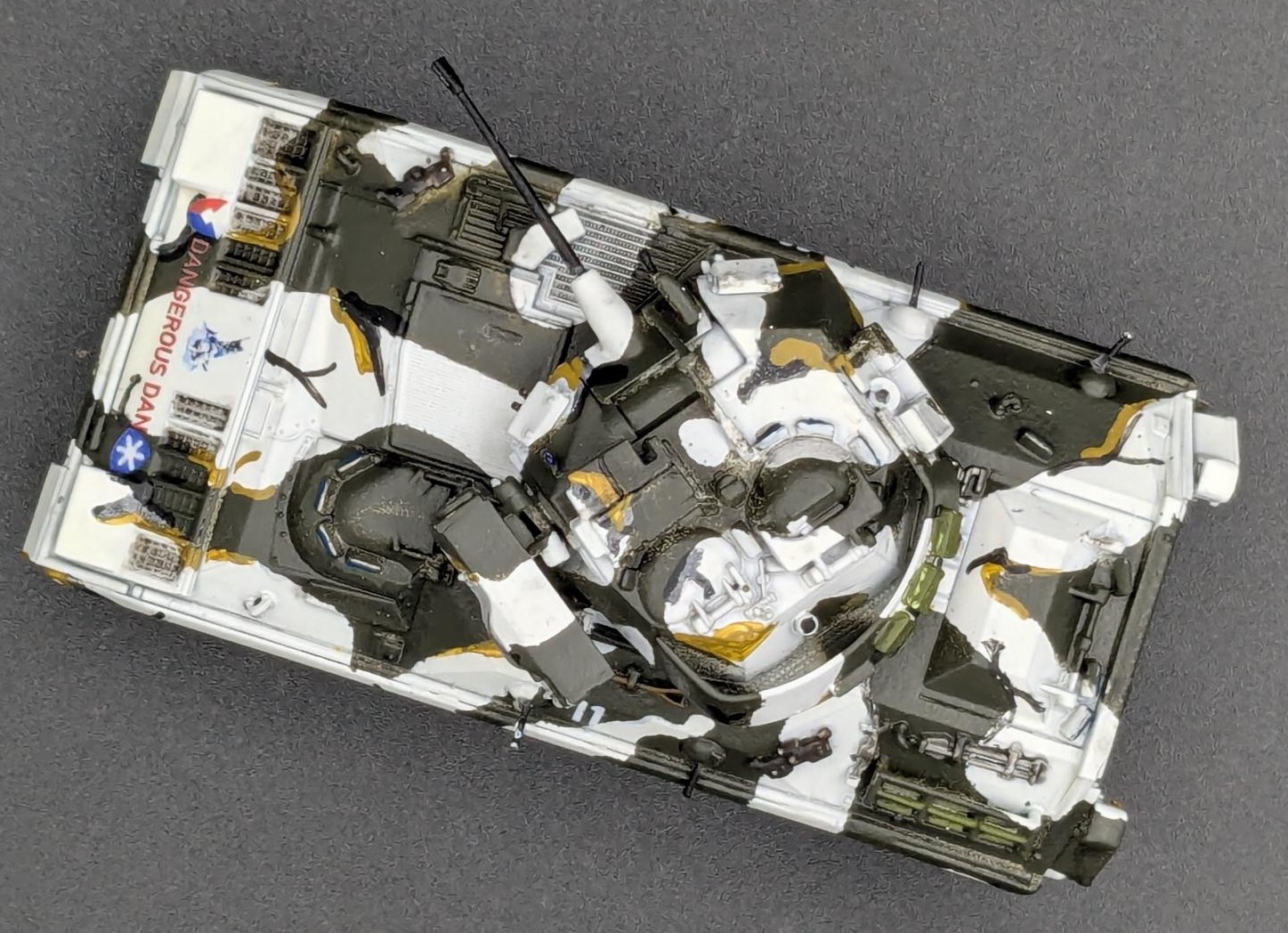
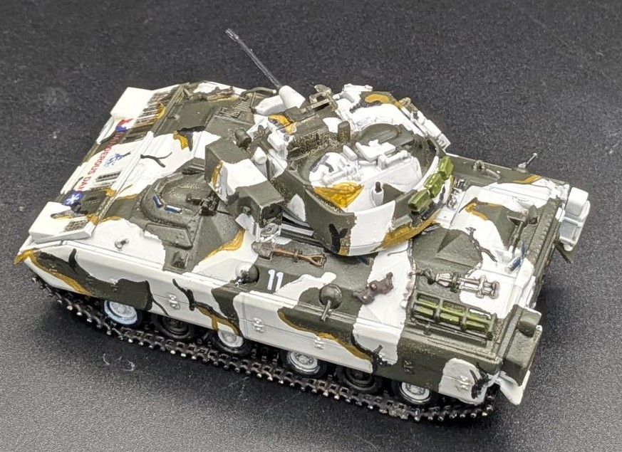
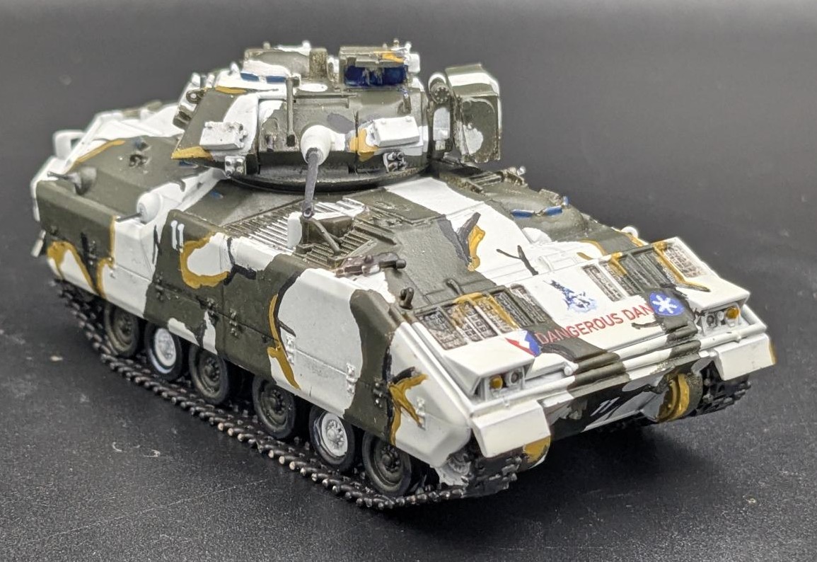
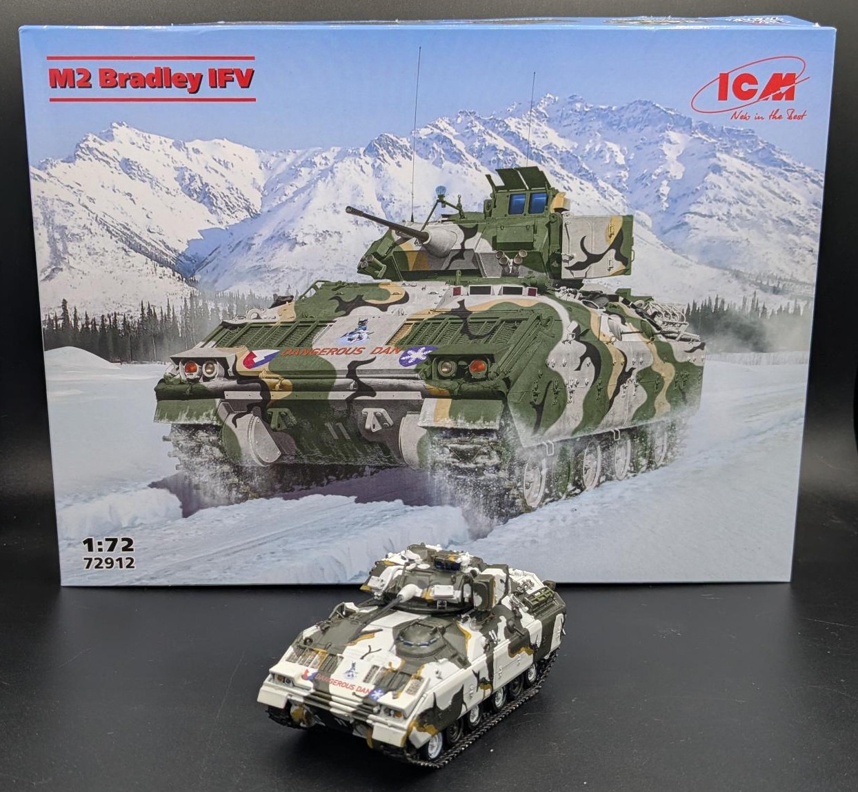
- M2 Bradley, US Army Cold Regions Test Center, Fort Greely, 1984 in snow with trees MERDC (US Army Mobility Equipment Research & Development Center) scheme
- M2 Bradley, 41st Infantry Regiment, 2nd Armoured Division, Fort Hood, 1985 in summer verdant MERDC scheme
- M2 Bradley, 3rd Infantry Division, West Germany, mid-1980s in overall green scheme
- M2 Bradley, Exercise Shadow Hawk ’87, 1987 (Jordan) in a desert MERDC scheme
I chose the US Army Cold Regions Test Center, Fort Greely, 1984 as a Bradley in a white MERDC camouflage is not very common and the color decals really pop. ICM conveniently provides Acrylic Paint Set for US Armored Vehicles 1990-2000s (Item No. 3087 - IPMS/USA Review).
The decals are delicate and conform well to the model, have no silvering and really look the part, care must be taken due to their small size and fragility as a few wanted to curl back on themselves.
Of note, both the Bradley M2 and M3 kit can be built from this kit as the parts for both are included, and the differences were pointed out in this review. The only difference is the decals included in their respective kits for Infantry (Kit No. 72912) and Cavalry (Kit No. 72913) Fighting Vehicles.
This is another beautiful braille scale model that has been given a second life, much like their real counterparts fighting for Ukrainian independence.
Slava Ukraini!
Profuse thanks to ICM and IPMS/USA for providing the review sample.
Reference the ICM Website
The M2 Bradley infantry fighting vehicle entered service with the US Army in 1981. It was developed through a long-term program called Mechanized Infantry Combat Vehicle, which aimed to create a protected, highly maneuverable transport for mechanized units of the US Army. The vehicle was named after Omar Bradley, the legendary American general of World War II.
The M2 Bradley serves a dual purpose: transporting motorized infantry units during combat and providing fire support. It features a traditional layout with the engine positioned in the front of the hull to better protect the crew. Both the hull and turret are constructed from aluminum alloy reinforced with other metals to increase damage resistance. This armor configuration provides all-around protection against 14.5 mm armor-piercing incendiary bullets.
The Bradley’s primary weapon is an M242 25 mm automatic cannon capable of penetrating 66 mm thick homogeneous steel armor. For engaging heavy armored vehicles, a dual launcher for BGM-71 TOW missiles is mounted on the left side of the turret. Throughout its service life, the vehicle has undergone various modifications and improvements that have significantly enhanced its protection capabilities.
Comments
Add new comment
This site is protected by reCAPTCHA and the Google Privacy Policy and Terms of Service apply.
Similar Reviews