
Do 217M-1 WWII RAF Bomber
Summary
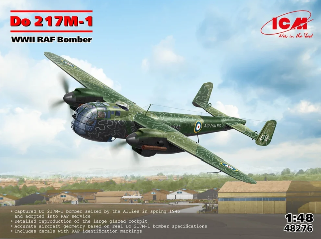
This kit is a re-boxing of ICM’s Do 217M-1 WWII German bomber (Kit 48274), but with a new decal set of RAF markings for a captured aircraft.
As with other ICM kits, this one is overflowing with detail and precise engineering.
Background
The following is taken from the ICM instructions.
“The German Do 217M-1 bomber was a variant of the Do 217 series, equipped with DB 603A engines producing 1,750 horsepower. Combined with four-blade propellers, this significantly improved the bomber’s flight performance and increased its maximum speed to 557 km/h, though at the cost of reduced range. The Do 217M-1 served with Luftwaffe bomber and reconnaissance squadrons until the end of World War II.
In spring 1945, the Allies captured one such bomber in Beldringe, Denmark. The aircraft received RAF markings and flew to Schleswig in September 1945. In October, it was relocated to Farnborough airfield in Great Britain. On October 18, it made its first test flight, and on November 4, 1945, it participated in a demonstration flight as part of a special squadron of captured Luftwaffe aircraft. The aircraft remained in Britain until the mid-1950s.”
What’s in the Box
All sprues come in ICM’s ubiquitous, sturdy, cardboard box, with a separate cover.
- 1 large bag with 3 large sprues, two for wings (upper and lower sections), and one with the tailplane and closed bomb bay door, (this sprue also contains a fuselage for the Do 217 K), and 1 medium sprue with the engine nacelles, open bomb bay doors, and various internal bulkheads.
- 1 large bag with 1 large sprue with the fuselage and interior parts, 3 medium sprues, two each for engine, nacelle, and landing gear parts, and 2 small sprues with various bombs.
- 2 small bags with clear parts.
- An 8-inch by 11.5-inch instruction booklet for assembly and painting of the model.
The Instructions
The instructions consist of a 20-page glossy 8-inch by 11.5-inch instruction booklet. The front cover provides a brief description/history of the aircraft, including technical data, in both Ukrainian and English. ICM paint colors and descriptions of the various pictorial symbol/notes are also on this page. The paint color chart has the letter callout used in the instructions, the color name, and ICM paint number.
Pages 2 through 4 and the upper part of page 5 are the parts maps for the 11 sprues of the Do 217M-1. Parts not used with this model are clearly shown in pink shaded boxes. Pages 5 through 16 are the assembly instructions for the model. The images are sharp and show the assembly as an exploded ¾ view. Page 17 shows a ¾ drawing of the completed aircraft and the instructions for assembling the SC500J (500 Kg bombs) and two types for 250 Kg bombs (SC250Ja or SD250Jb).
Page 18 has masks and placement drawings for the clear parts. Pages 19 and 20 are the paint schemes. Page 19 shows the paint callouts for the airframe as captured with the upper surface splinter camouflage, black sides and bottom, but no decals. Page 20 shows the RAF version where a white squiggle pattern has been added over the splinter camouflage and a dark green band added around the fuselage near the tailplane. This also shows the decal placement. Both painting pages show four views; left, right, upper surface, and lower surface. These pages also have painting callouts for the spinner/propellers and two insets (left and right side) of the aircraft from that are hidden in the left and right-side views by the engine nacelles.
Things to Consider Before Starting
From the very first step one must decide if they want an early war (grey green, aka RLM 02) or late war (dark grey, aka RLM 66) interior color. To keep things straight I suggest crossing out the color callout that is not going to be used.
There are other choices to be made during construction. I will note those in the appropriate section but will call them out here, so one can start construction with some idea of what to expect.
Starting with steps 21, 22, and 24, one must decide if they want a single MG81Z or dual MG81Z machine guns. Step 25 has options for the tail end of the aircraft. Either plain or with two remote control machine guns. Steps 31a and 31b are for closed (31a) or open (31b) bomb bay doors.
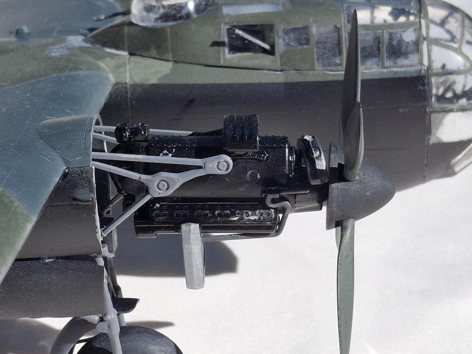
One of the biggest choices is Steps 48 through 67. Unlike other ICM aircraft kits that I have built where the engines are integral to the completed model and can have the nacelle panels either built around the engines or left off to display the engine, this model is different. If one chooses to display an engine, then the nacelle sides must be removed. As the engines, as is typical, are beautiful little models on their own I chose to do one nacelle with the engine displayed and one without. Steps 48a through 67a are for displaying the engine. Steps 48b through 67b are for solid nacelles. If one chooses to do one of each, I strongly recommend crossing out the steps not applicable to the side (left or right) you are not using for each nacelle version. (This is made easier are the figures are labeled as “Left Engine Nacelle” and “Right Engine Nacelle.”
Construction
I start all my builds by scrubbing the sprues with an old toothbrush in warm water and dish soap (Dawn) to remove any residual mold release residue.
Many parts are scale thin, so use caution when scrubbing them and removing these parts as they are prone to breaking or disappearing into the ether if not carefully cut from the sprue.
Cockpit and Interior Details
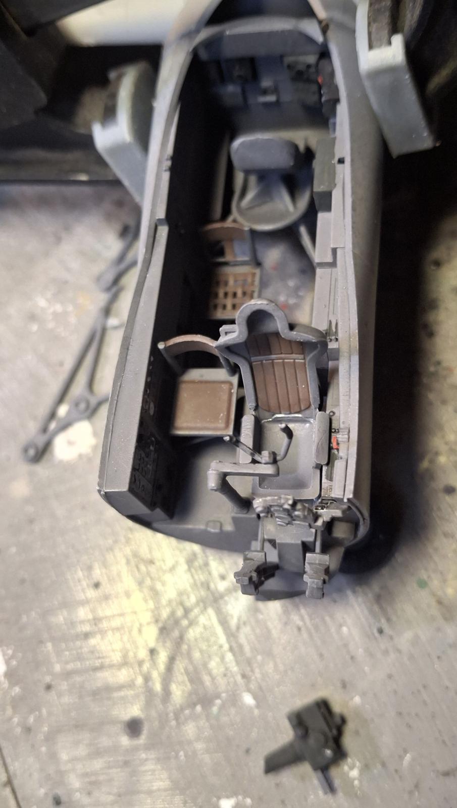
With careful review of the instructions, one can determine what can be built as sub-assemblies and painted the same color. I assembled most interior parts in Steps 1 through 20, leaving off parts that were not dark grey. This included the radio operators’ seat in Step 13, but I did attach part K11 in Step 13.
Caution notes on interior construction. Although not shown clearly the foot pedals in Step 06 angle slightly to the bottom where they attach to the lower floor. Do not permanently attach the floor in Step 11 until after Decal 4 is attached. In Step 17 the front of the right-hand side panel is slightly behind the front of the fuselage side. This is important as it must fit against the floor glued to the left side of the fuselage. To do this accurately I held panel (from Step 16) in place with a small clothes pin. Then held the fuselage halves together with rubber bands. I could then adjust the panel to fit tight against the installed floor and glue it in place.
Finally, you know how there is always that one piece that just begs to be broken off before the model is complete. In this kit that is the bomb sight (Step 04). It not only sticks out from the floor but sticks out from the front of the fuselage. I strongly recommend not attaching this assembly until the clear front canopy (Step 24) is being permanently attached.
I pre-painted the bomb sight in step 04 and part E45 in Step 08. After painting the interior sub-assembly, go back and attach the pre-painted parts. I brush painted the seat cushions (Parts K36 and K29) and steering column handle (Part K12). I also picked out the various dials with flat black, and switches with flat, black, white, and red. After the paint had cured, I added touches of clear gloss to the left and right-side control panels where decals 1, 2, and 4 are to go. When the clear gloss dried, I applied the decals.
With the interior painted and decaled, I assembled to model through Step 47 with the following notes. Steps 21 through 24 require the builder to decide if they want a single MG81Z machine gun or a dual MG81Z machine gun in the front glass. I chose the simpler single machine gun. If one chooses the dual version, then the opening in clear part J1 must be opened wider. Refer to the instructions for the necessary change. Step 25 has the option for the rear of the aircraft. It can be either plain (25a) or with two remote control machine guns (25b).
I did not attach the machine guns in Steps 24 or 29 as these would surely break off during painting and handling. I also only temporarily attached the clear parts (J1 and F2) with Elmer’s glue. The machine guns and clear parts would be permanently attached after painting the exterior. Although assembling the tail wheel (Steps 27 and 28) I did not attach them until after painting the exterior so they wouldn’t need to be masked.
Step 31a is for the closed bomb bat door. Steps 31b through 34b are for an open bomb bay. In Step 33b there are three different options for bombs.
Wings
The wings and tail planes went together without trouble. The option noted in Step 35 of 31a or 34b refers to the fuselage with a closed bomb bay (31a) or open bomb bay (34b). To help with exterior painting the dual rudders (Steps 38, 39, and part A3 and A4) can be left off and painted separately. But the tailplane (completed in Step 43) should be attached in Step 45.
Engines
Starting with Step 48 a major decision must be made by the builder. Do you want to show the engines or not? Unlike other ICM aircraft models I have built where the engine is an integral part needed to hold the propeller and the nacelle panels can be built around the engine or left off; this model is very different. If the builder wants to display one or both engines, then the front of the nacelles must be removed (cut off). Steps 48a through 67a are construction of nacelles and engines. Steps 48b through 67b are construction of the nacelles without the engines. Since the engines are nicely detailed, I chose to do one of each, a nacelle with the engine and one without. To do this one must refer to Steps 57b and 58b to learn which nacelle constructed in Steps 48b/49b or 50b/51b is the right or left nacelle.
NOTE: Steps 48b/49b builds the Left Engine Nacelle. Steps 50b/51b builds the Right Engine Nacelle. To keep things easy, I recommend crossing out the a / b steps for the nacelle that is not being built.
To build the:
- Left Engine Nacelle WITH Engine: Steps 48a, 49a, 52a - 65a.
- Left Engine Nacelle WITHOUT Engine: Steps 48b, 49b, 52b - 57b, 59b, 61b - 63b, 64b, 66b.
- Right Engine Nacelle WITH Engine: Steps 50a, 51a, 52a - 63a, 66a, 67a.
- Right Engine Nacelle WITHOUT Engine: Steps 50b, 51b, 52b - 56b, 58b, 60b - 63b, 65b, 67b.
Landing Gear
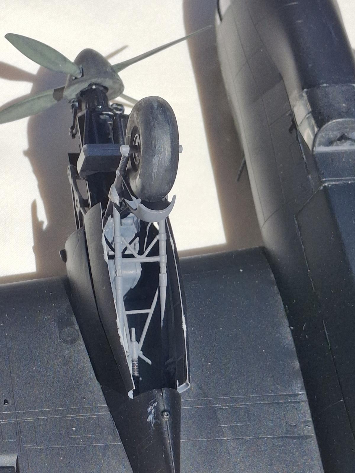
I constructed the landing gear (Steps 68 through 72) but did not attach them (Steps 71 and 72) to the nacelles. This avoided breaking them during handling and required they not be masked when painting the exterior.
Wings, Part 2
The engine nacelles attach to the lower wing in Step 79. The engine nacelles fit tightly with no gaps. The only issue of note is to clamp the nacelle extension on the upper wing piece to the top of the engine nacelles to ensure there is no gap.
Partial Completion Assembly
I completed Steps 81, 82, and 85, (though the machine guns were again left off).
I temporarily attached the upper cockpit with Elmer’s white glue. This would allow easy removal after painting to install the machine guns before permanently attaching it.
Final Assembly
After painting the upper and lower surfaces I attached and completed tail wheel assembly (Step 28), the landing gear assemblies (Steps 68 through 78), and the left engine and bracket (Step 64a). This was followed by attaching all the machine guns. Then permanently attaching all the clear parts (the front glass [part J1], lower cupola [part F2], upper cockpit [part J4], side windows [J2 and J3 with machine guns added], lower antenna cover [part 4], and the upper machine gun and turret [Step 87]. Finally, all the remaining “fiddly bits” (pitot tube, antennae, etc.).
Painting and Finish
After assembling all the interior parts in Steps 1 through 20 I primed the interior assembly with Rust-O-Leum 2X Flat Gray Primer. I allowed this to cure for 48 hours. As noted in the “Things to Consider” section the builder has the option of a grey green (aka RLM 02) or dark grey (aka RLM 66) interior color. As this aircraft was captured in 1945, I went with the late war RLM 66 interior. For this I thinned and airbrushed Mission Models MMP-089 Dark Grey RLM 66. After this dried overnight I picked out dial faces with Tamiya XF-1, flat black. The bomb sight (Step 04) also painted Tamiya flat black. Knobs and switches were picked out with Tamiya X-1, white; X-7 flat red and XF-85, rubber black. Location for decals 1, 2, and 4 were touched with a bit of Mission Models clear gloss, MMA-006. When dry the decals were placed the sealed with Mission Model MMA-004, flat clear coat. A touch of Mission Models clear gloss was used to represent glass on the instrument dials.
Instead of the black or dark sea grey recommended for the seat cushions I went with AK leather brown (AK11110) for a bit more color in a rather monotone cockpit. The adjustment wheel on the rear of the pilots’ seat was painted Mission Models MMM-002, cold rolled steel and Tamiya XF-64, dark sea gray.
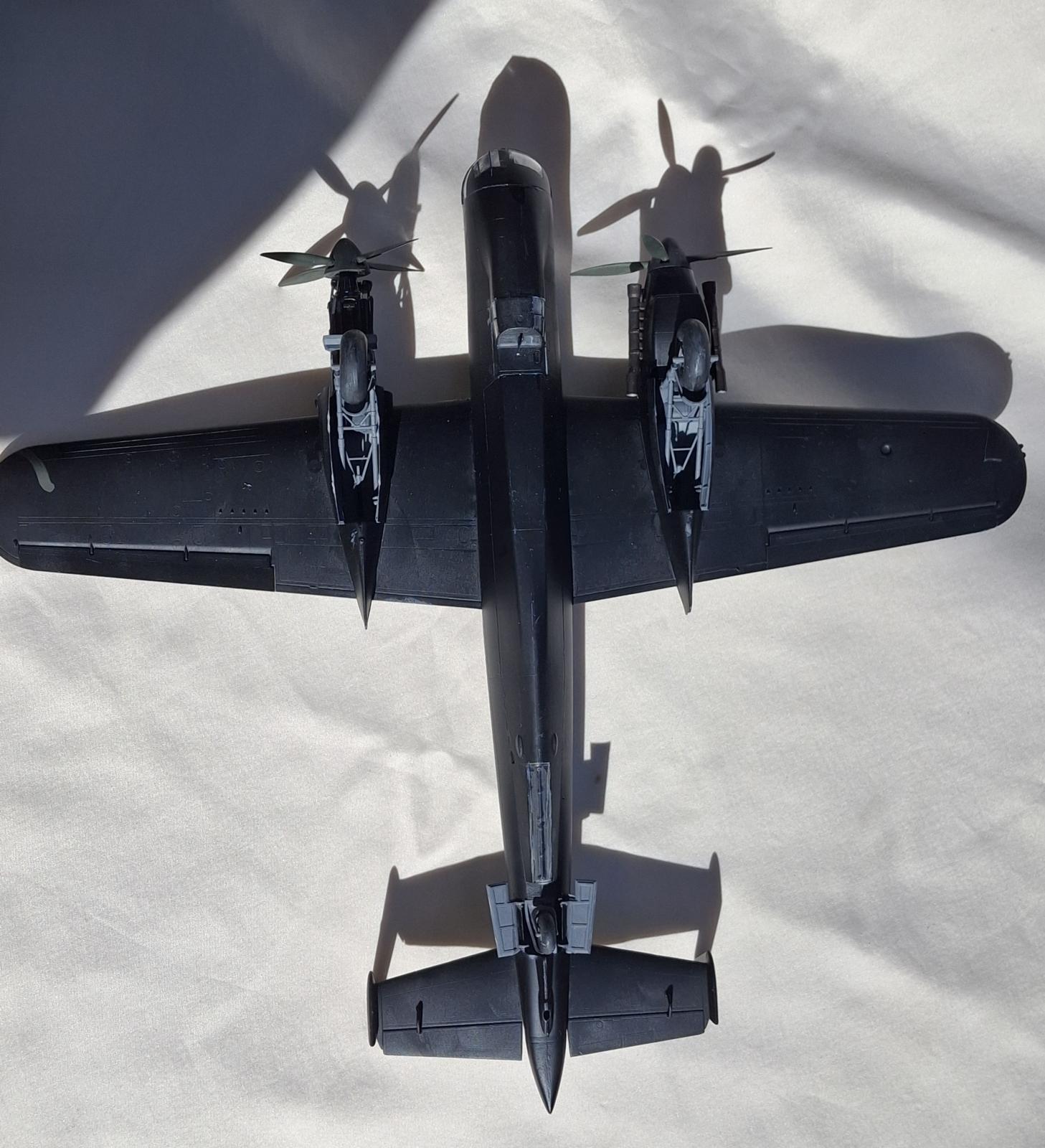
After painting the interior, the fuselage was joined and construction continued through Partial Completion above. The bomb bay, landing gear, main wheel wells, tail wheel assembly, and engine mounts were all primed with Rust-O-Leum 2X Flat Gray Primer. They were then airbrushed Mission Models MMP-089 Dark Grey RLM 66.
I printed out the masking templates on an inkjet printer onto an Avery full adhesive sheet. These were then carefully cut out with scissors and then placed on the front glass, upper cockpit, and lower cupola windows. Once masked these parts were temporarily attached with Elmer’s white glue for easy removal after painting. Open areas of the airframe, such as the tail wheel and main wheel wells and upper gun turret were filled with pieces of urethane foam for masking.
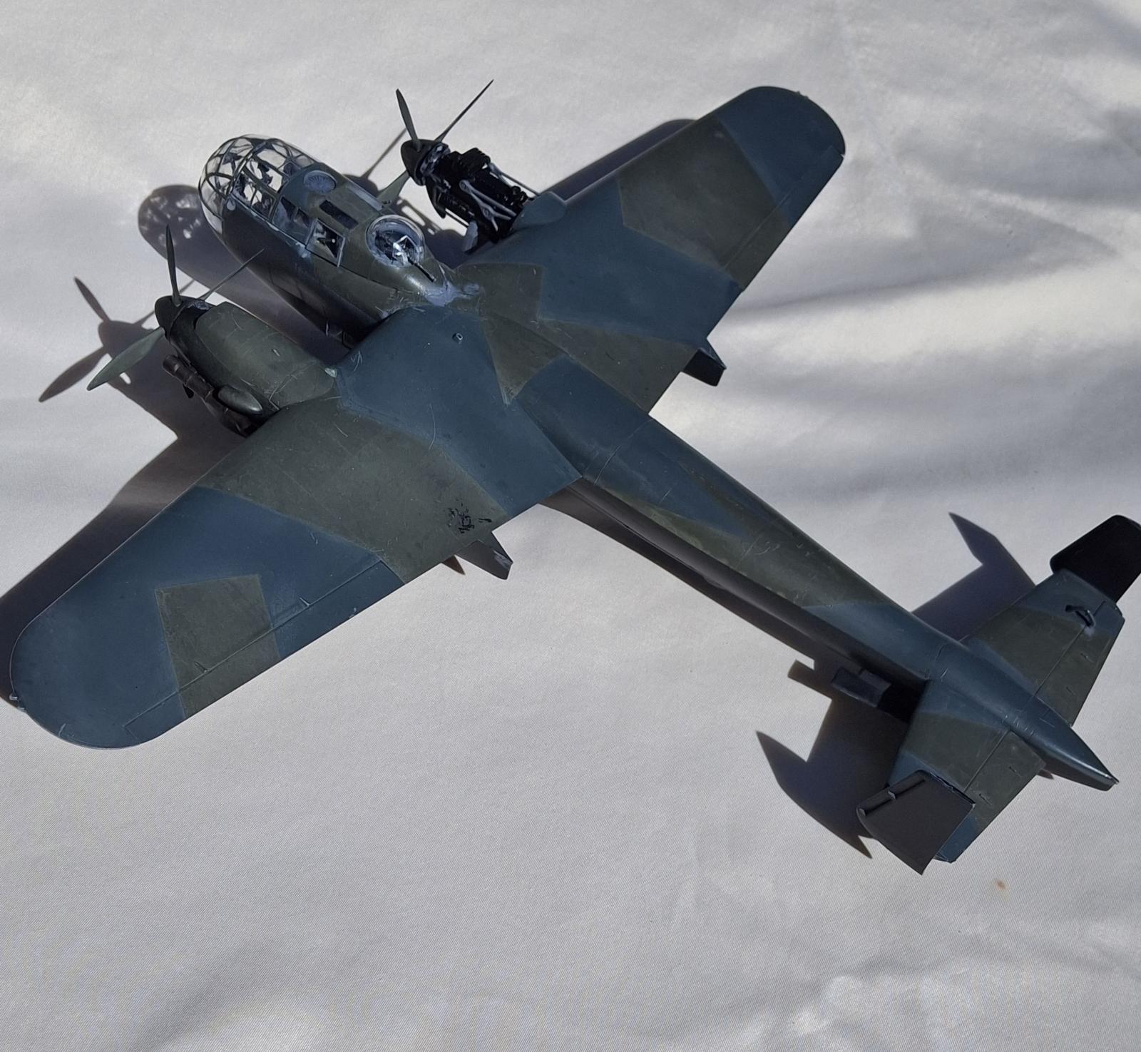
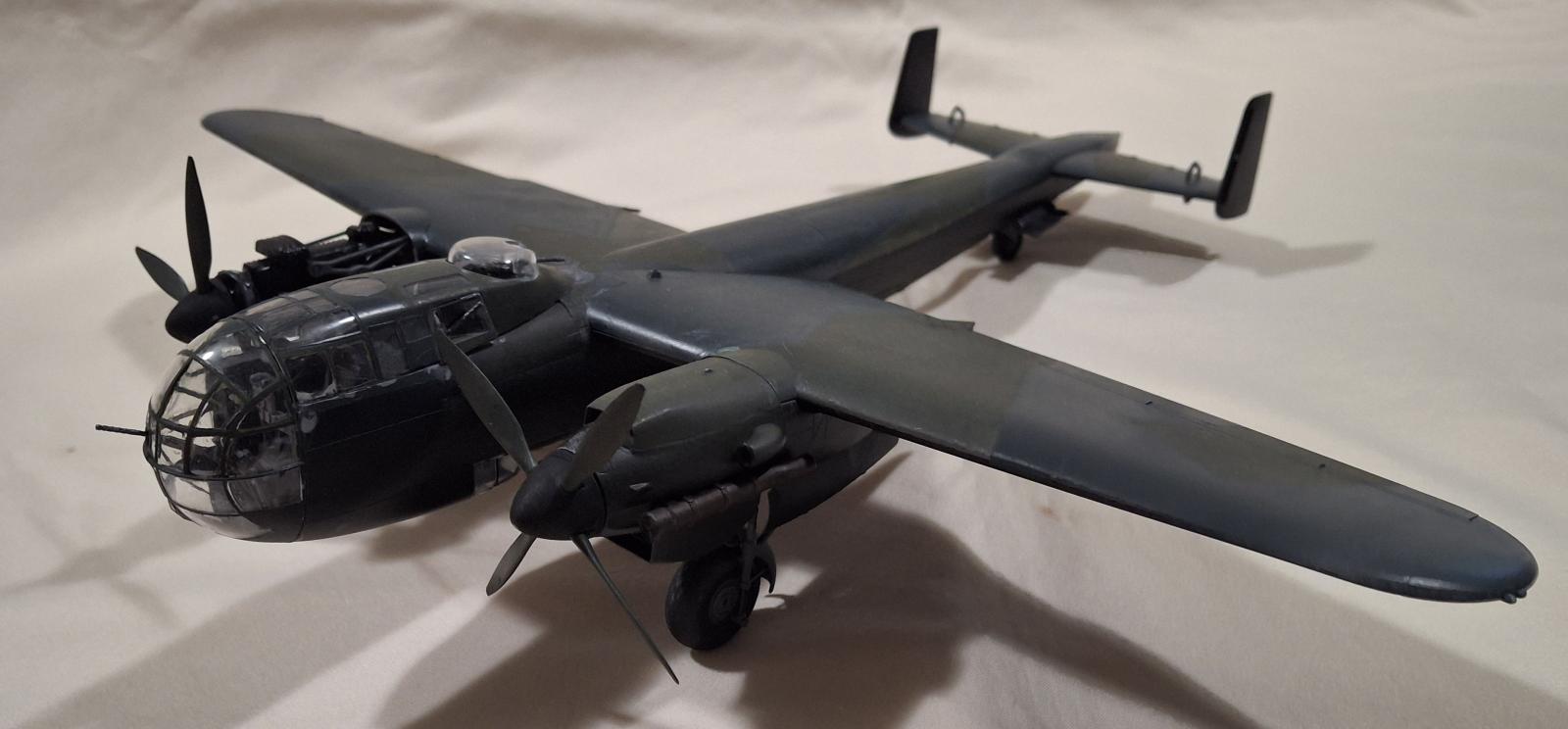
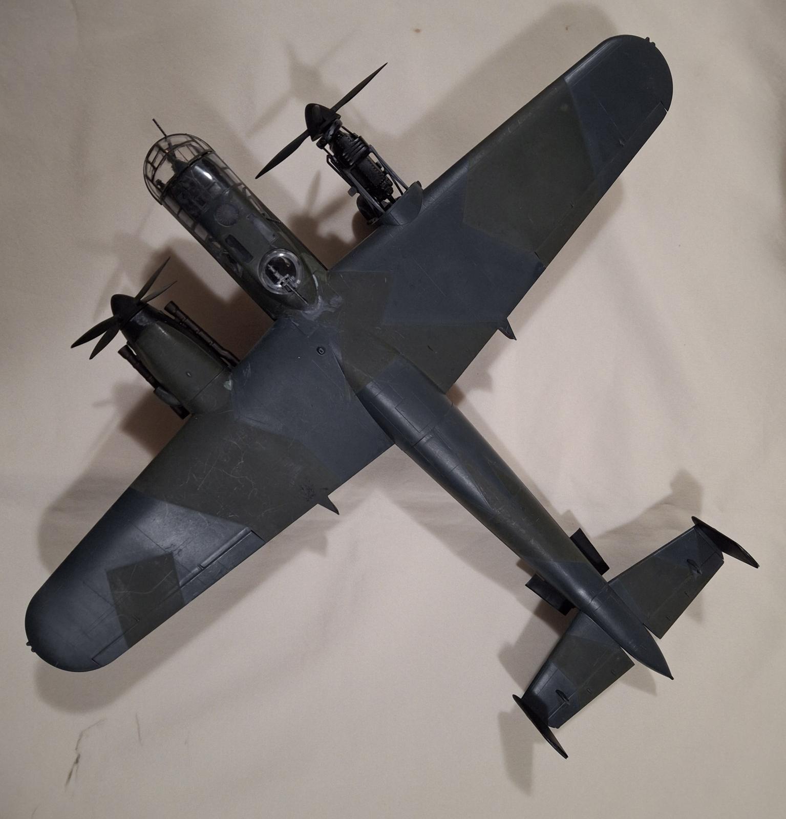
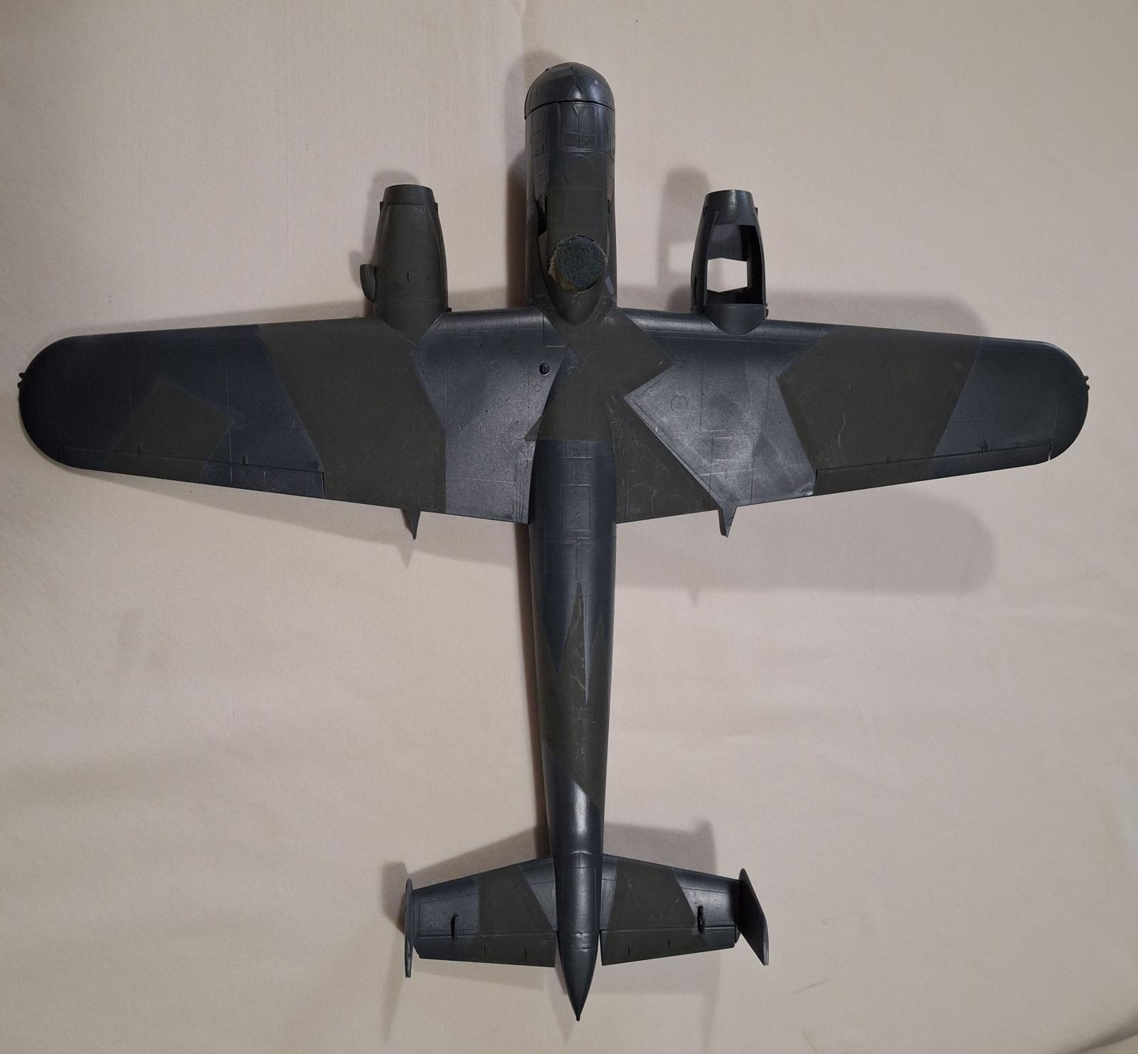
The entire masked model was primed with Krylon Fusion matte black All-In-One Paint + Primer. This was allowed to cure completely over several days. Then the lower portion of the fuselage sides and engine nacelles were masked off. The areas to be painted camouflage green were masked off. After masking the upper surfaces and upper sides were airbrushed Mission Models Dunkelgrun RLM71 (MMP-087). When this was finger-dry the green masking was removed. The paint was allowed to cure completely. Next the dark green was masked with Tamiya masking tape. First with 2mm masking tape, then 3mm masking tape, and finally 6mm masking tape, each size partially overlapping the previous size. The larger areas were filled with 3M blue painter’s tape. Once fully masked the extra dark green was airbrushed with Mission Models Schwarzgrun RLM 70 (MMP-088). Again, this was allowed to dry to finger dry before the green masking was removed, and the paint allowed to cure completely.
The final paint was to mask off the upper surfaces and spray the undersides, most of the fuselage, and rudders Tamiya matt black (TS-6) from a spray can. When cured completely all masks were removed. The clear parts were also separated and their masks removed.
Individual parts were primed with the Rust-O-Leum flat gray primer. Machine guns were painted Tamiya X-10, gun metal before being installed in the clear parts. Exhausts were painted Tamiya dark iron (XF-84). Parts called out as Oily Steel were painted Mission Models cold rolled steel, (MMM-002). Rubber black items, engine hoses, main and tail wheel tires, were painted Tamiya XF-85, rubber black. The propeller spinners were painted Tamiya flat black, while the propeller blades were painted Mission Models Dunkelgrun RLM71.
As of this writing I have not “passed” my attempts at applying the white squiggle pattern or final decals. I will submit an update when that is finished.
Decals
The decals are well printed and opaque. Past ICM decals tend to be very thin, making them equally very fragile. I also found they were prone to folding over on themselves. Being thin and fragile unfolding them is almost impossible without breaking/tearing them. I also found that they required more than the normal time in warm water before they could be slid off the backing paper, upwards of 20 to 30 seconds. I found that all decals reacted well to Microscales Micro Set and settled in well with Micro Sol.
As of this writing I have not applied decals to the model, waiting for my application of the final squiggle pattern to be applied.
Conclusion
I recommend this kit for intermediate to experienced modelers. The build is straight forward with only a few very small, fragile parts to deal with. The large amount of glass requires careful masking, using either the supplied masking templates or an aftermarket masking set.
By carefully reviewing the assembly sequence laid out in the instructions it is easy to see where sub-assemblies can be created to help with painting. The thin and fragile decals require careful handling, but nothing beyond most modelers’ capabilities.
I would like to thank ICM for providing this kit for review, and IPMS/USA for giving me the opportunity to build it.

Comments
Add new comment
This site is protected by reCAPTCHA and the Google Privacy Policy and Terms of Service apply.
Similar Reviews