
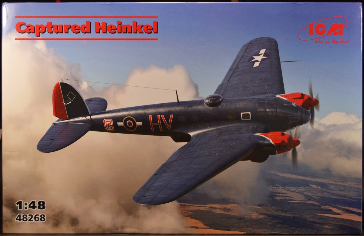
Captured Heinkel, He 111H-20, Part 1
ICM has reboxed its He 111 kit for a unique Captured Heinkel scheme in 1/48th scale. The instructions give a very interesting history of this captured He 111H-20 transport variant:
Unique History
One of the He 111H-20 aircraft has a remarkable history. Built as a transport variant of one of the Luftwaffe's most widely produced bombers, it was manufactured in 1944 with factory number 701152. During the final days of World War II in Europe, American forces captured and transported it to Cherbourg. The pilots of the 56th Fighter Group USAAF, who were assigned the aircraft, painted it their unit's signature deep purple color. By September 1945, when it was time to return to the USA, the American pilots faced leaving the aircraft behind. Unwilling to abandon it, the crew made a daring decision -without higher command's approval, they flew their He 111 to the British airbase at North Weald, where bewildered British pilots discovered it on their airfield the following morning. This bold action ensured the aircraft's preservation. It was subsequently featured at the German aircraft exhibition at RAE Farnborough (Royal Aircraft Establishment), before finding its permanent home in 1978 at the Royal Air Force Museum in London, where it remains today.
In The Box
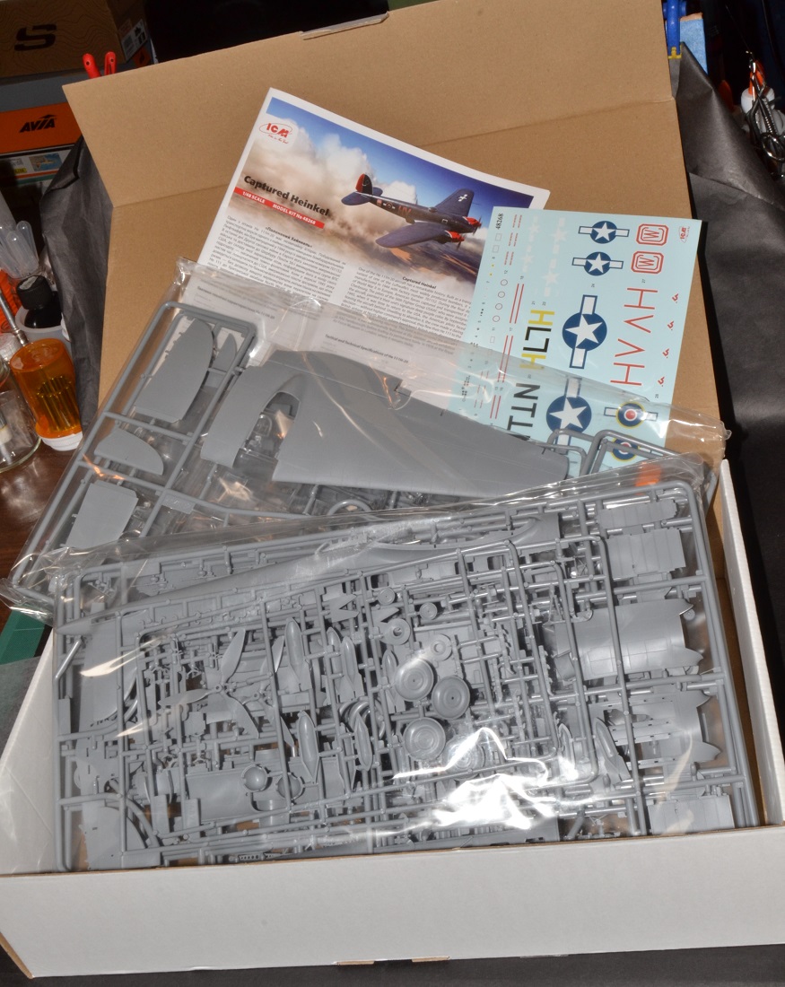
The kit is enclosed in sturdy packaging with an illustrated cover top and a cardboard casing. The main gray sprues are in two plastic bags and each clear sprue is in its own plastic bag for protection.
Instructions are well illustrated and easy to follow and contain 107 steps for assembly. It is worth noting that for the “H” transport variant has a lot of parts that will NOT be used, and those parts are highlighted in the instructions.
For painting reference, ICM uses their line of paints, but you can easily look online to cross reference other paint brands for color matching.
Decals are thin and in registry and have three sets of markings for the He 111H-20 during its captured time in 1945:
- He 111H-20, 56th Fighter Group (USAAF), Boxted Airfield, July 1945 (splintered green camo & black underside).
- He 111H-20, RAF North weald, September 1945 (deep blue-purple with red engines nacelles & rudder, US markings on the fuselage).
- He 111H-20, RAE Farnborough, November 1945 (deep blue-purple with red engines nacelles & rudder, British markings on the fuselage).
Review Process for Part 1
This is a box stock build with no added aftermarket. However, I did take some liberties with assembly sequence to try and make it an easier task. Recommendations will be noted to help the modeler make this an easier build experience.
Since this is my first time to build this kit, I did try and follow the instructions sequence as best I could before I had to make changes for ease of assembly. In the instructions, it is optional for the builder to add/leave off the machine guns. I left off all the machine guns since this was a captured transport plane and I figured German ammo was in short resupply for the USAAF.
Recommendation 1: When test fitting the fuselage and wing halves together, you will notice some aligning pins will not fit into the receptacles. This is because the receptacles are too small and/or the pins are too long. A drill bit is needed to enlarge the receptacle holes and sprue cutters will be needed to shorten some aligning pins.
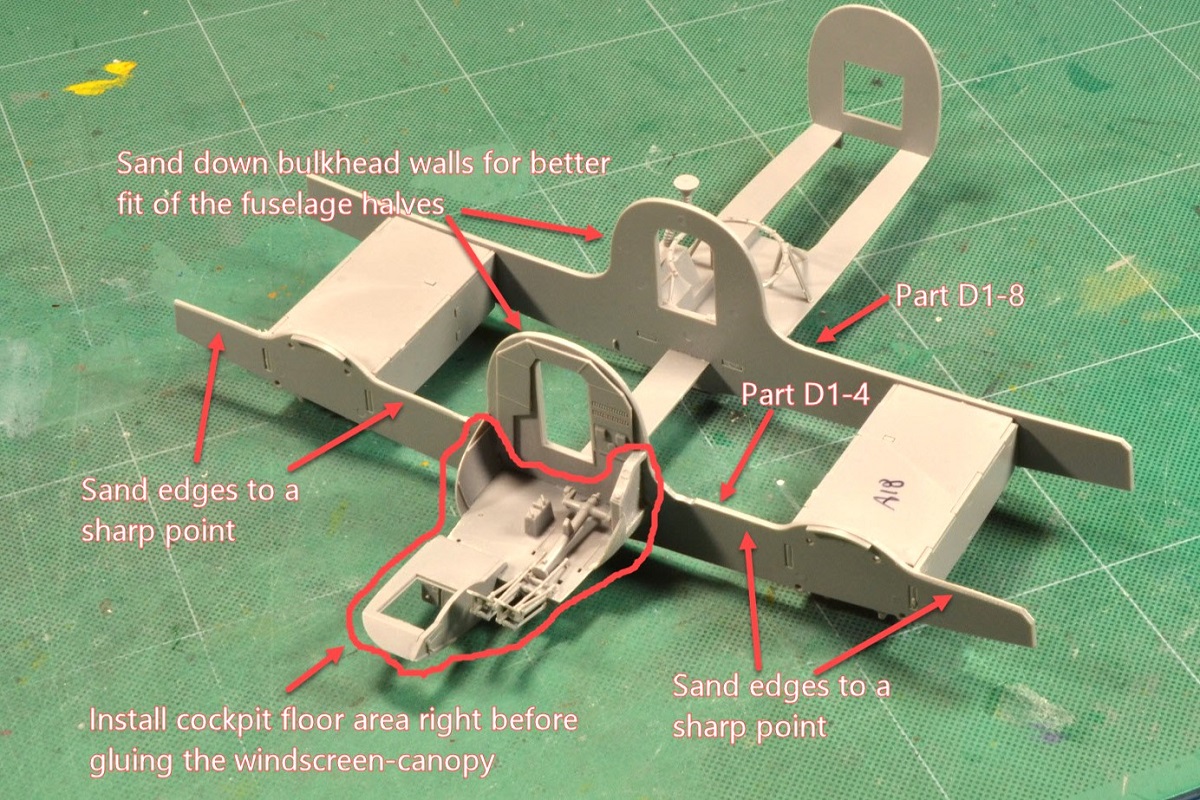
ICM has you assembling the interior structural area for the wing spars/bulkheads in steps 1-9. Then it has you attaching the cockpit in steps 10-21.
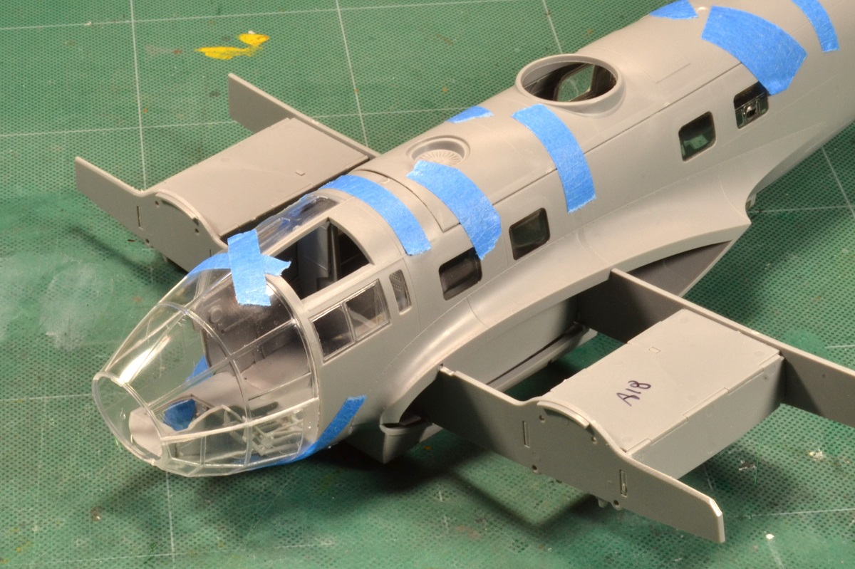
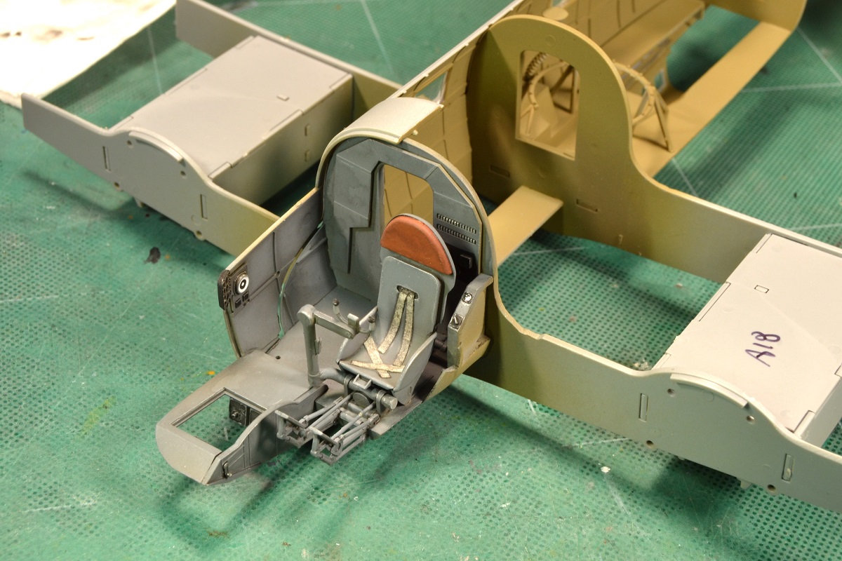
Recommendation 2: Do not build the cockpit into the forward wing bulkhead (D1-4) until later. However, do build the cockpit as a separate assembly onto the floor structure (D1-26) per step 12-21. The reason is the foot pedals will be broken easily since they will stick outside the nose fuselage unprotected for most of the build. Install the cockpit right before attaching the windscreen-canopy to lesson this chance of foot pedal breakage.
From steps 22-35 you can install the fuselage windows and side interior structure and assemble the tail wheel but do not permanently affix the tailwheel to the empennage of the fuselage.
Recommendation 3: Install the tail wheel near the end of the assembly. This will require you to cut the bottom part of the fuselage receptacle holes to make it into a slot to receive the tail wheel later.
At this point in step 37, begin the process of test fitting the two fuselage halves together over the wing structure and install the bomb bay side panels now, parts A11 & A12 from step 45-46, to make painting the interior easier.
During this process, I had trouble with a gap in the forward fuselage in the wing area. To help shorten/remove this gap, I sanded the top & sides of the bulkheads ( D1-4 & D1-8) to allow the fuselage halves to come in closer.
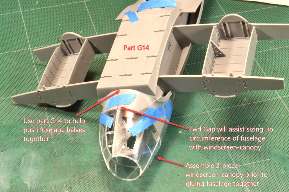
Recommendation 4: Use part G14 (step 48) bomb bay cover as a clamping guide to push the bottom halves of the fuselage together. It is shaped to conform to the curvature of the bottom fuselage and will push parts together.
This still left a wedge gap in the forward side of the seam; however, this gap will help in sizing up the windscreen-canopy.
Recommendation 5: Assemble the nose windscreen-canopy together (E3-3, E16, & E9) per step 86-87. By doing this, you can check fit to make sure the forward fuselage cockpit structure will mate correctly to the windscreen-canopy. Also, you may want to coat the clear parts with Future (or similar) to protect it from any crazing fumes from CA if that is the bonding agent or filler you will use.
The bottom gap can now be “sized” to fit the windscreen-canopy with the cockpit structure. This will ensure a tight fit between parts, but filler and sanding will be needed.
I had the fuselage taped together at this point and next was check fitting the wings over the spars. When placing the wings over the spars, a huge gap was evident on the leading edge. Upon further investigation, the forward wing spars were not sliding into the interior locating channels along the bottom side of top wing halves. To remedy this, I sanded the top edges of the spars (D1-4 & D1-8) to a sharpened edge that would allow the spars to recess into the channels.
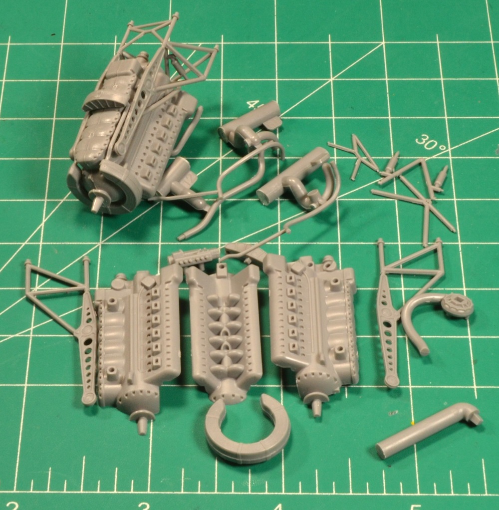
The engine assembly (Steps 57-68) is very straight forward, and the fit is surprisingly good. This area will entice AMS builders to super detail the engine since a good working base from the kit’s parts are already there.
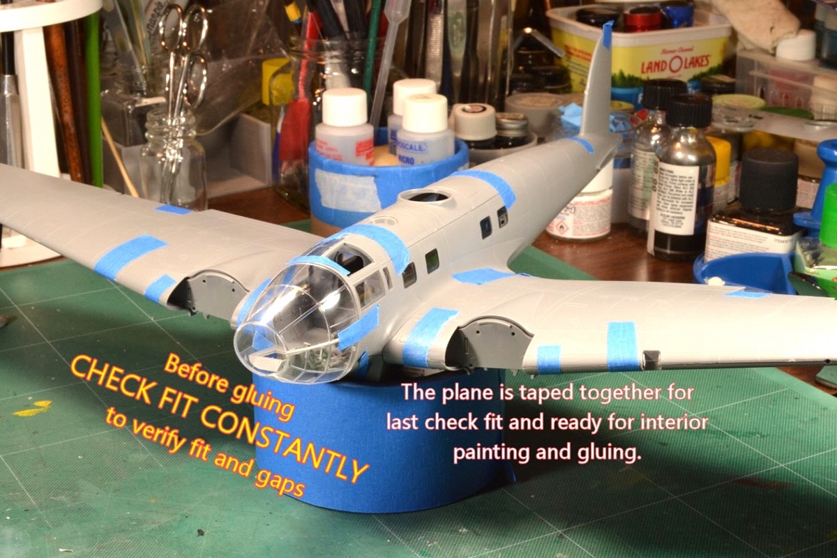
Once the fuselage and wings were check fitted multiple times, a final check fit with tape proved all the sanding made a difference in removing gaps. Now it was ready to paint the interior and cockpit and commence gluing parts together.
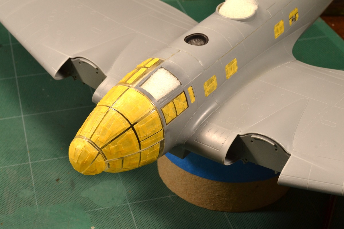
Recommendation 6: Masking the clear parts is a multi-hour exercise in patience and dexterity. I spent about 3 hours on this task. I highly recommend buying a masking set for your mental well-being.
In the tail, the horizontal stabilizers use a compress fitting method to install the parts into the empennage. However, the mating surfaces will need sanding down around the perimeter to get it to recess all the way down into the empennage. Otherwise, it will leave a huge gap.
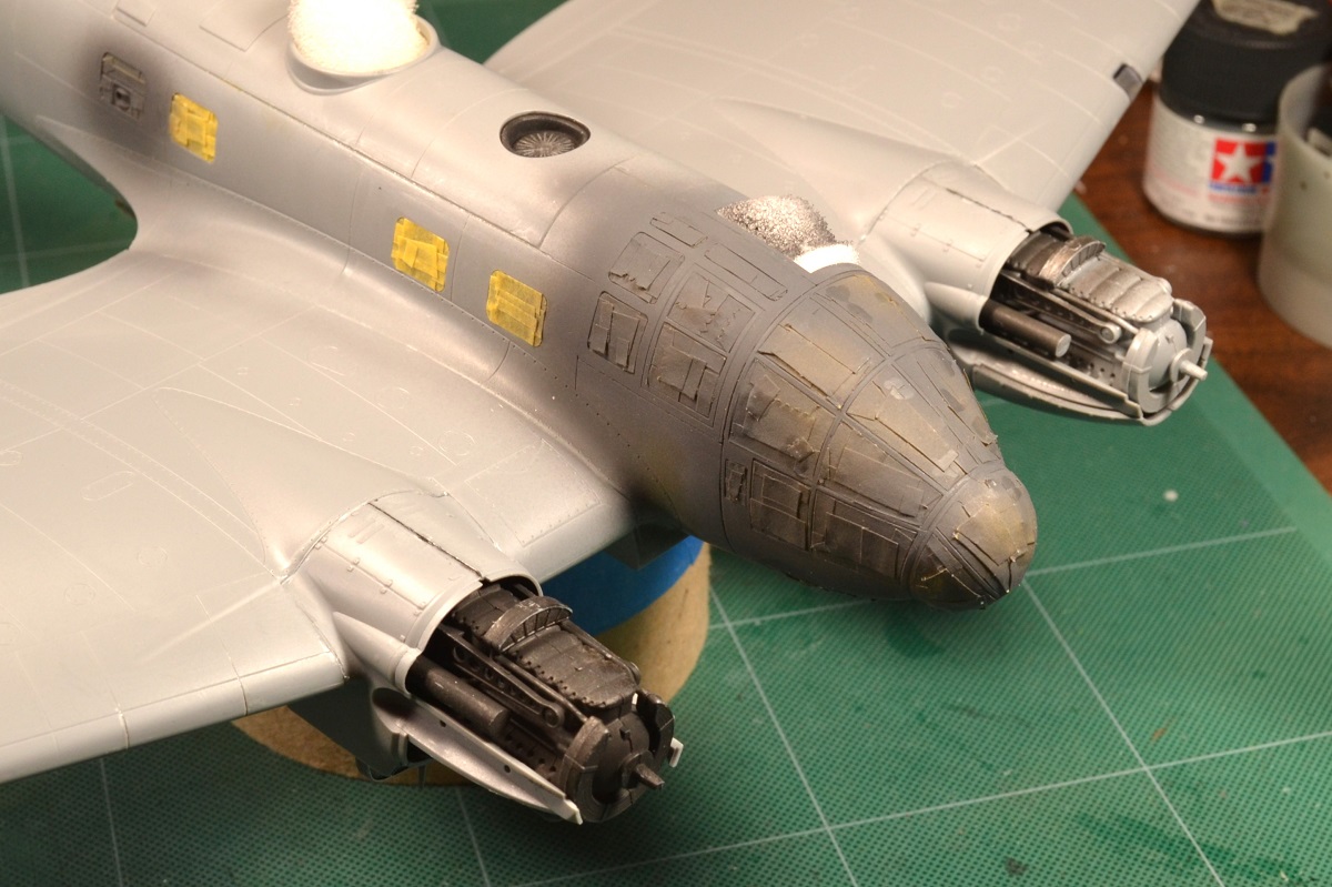
Engine cowling installation has some gap and tight fit obstacles based on seeing YouTube build videos for this ICM kit. I tried a different approach by not installing the engines or cowling covers per the instructions. Instead, I installed the upper and lower parts of the wings to the fuselage first. This presents its own set of challenges by trying to get the upper covers (parts D1-18, D1-19, D1-20, D1-21) to fit within the leading edge of the wing once the engine is installed. To make this work, I installed the RHS panels first. Next, I then installed the engine along with the LHS panels. This took some bending and forcible efforts to manipulate the parts into place but once in, they are a tight fit. Then I installed the rest of the engine covers but had to sand off some of the mating edges to reduce the step between overlapping parts.
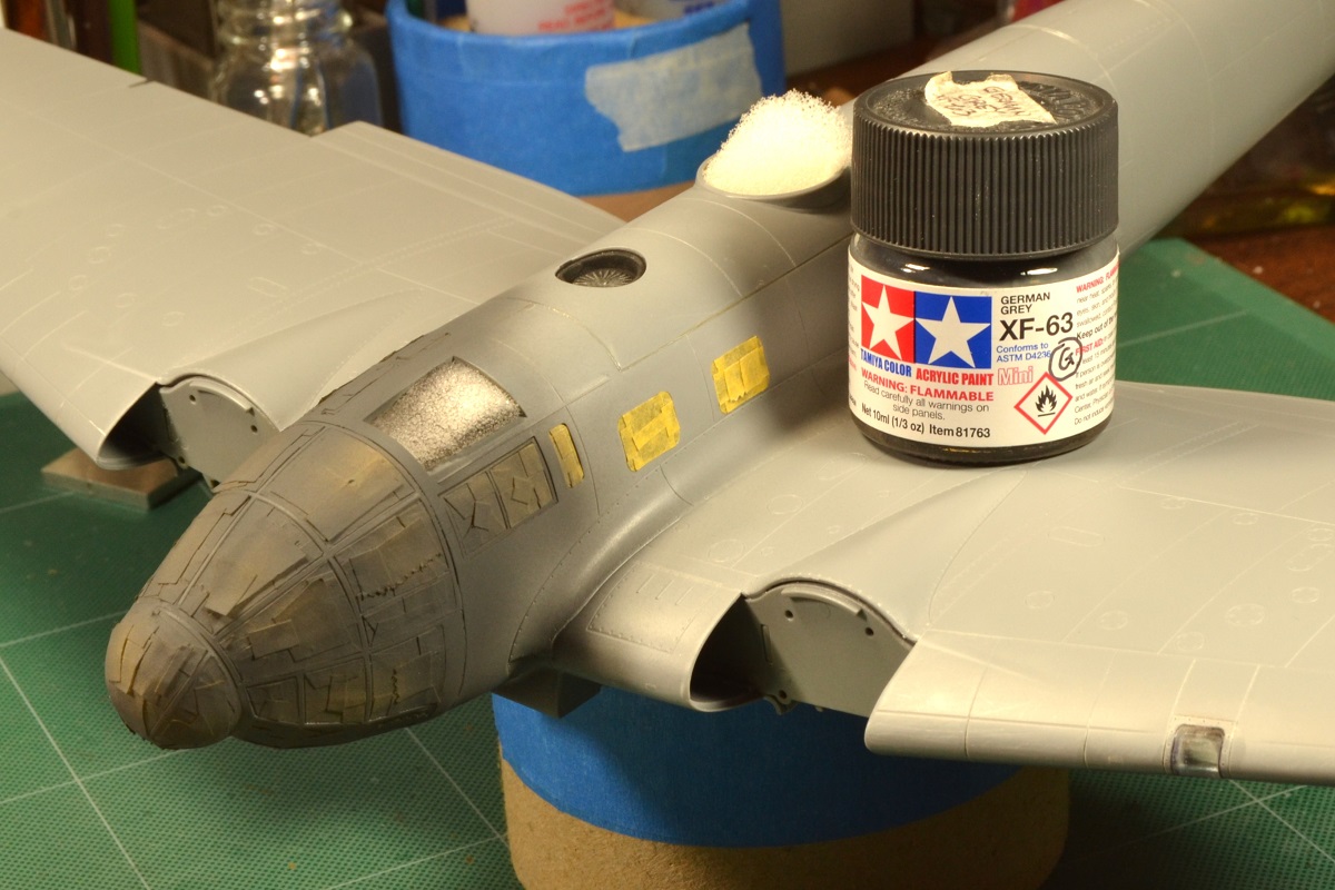
After that, I primed it with Mr. Surfacer 1000 gray and painted the engines and windows white.
These deviations and fixes made for an easier assembly in some areas while creating other issues at different steps. Just know this is a big kit in 1/48th scale and patience is needed to get it to the finish line.
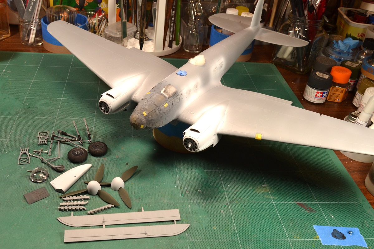
At the time of this unboxing and initial build review, the assembly is about 75% complete. PART 2 will be a review of the completed model.
Conclusions for Part 1
This is a good kit to build. However, you must be willing to exercise patience and explore why some parts do not fit as easily compared to other kits of this size. Nothing is impossible to remedy and I hope my suggestions will help in the pitfalls others may face when building this He 111.
I want to thank ICM for providing the He 111 Captured Heinkel kit and IPMS/USA for allowing me the opportunity to review.
Highly Recommend to those who have few kits under their belt and the finished build review will appear in Part 2.
Comments
Add new comment
This site is protected by reCAPTCHA and the Google Privacy Policy and Terms of Service apply.
Similar Reviews