
Airfield of the Luftwaffe Bomber Group
Summary
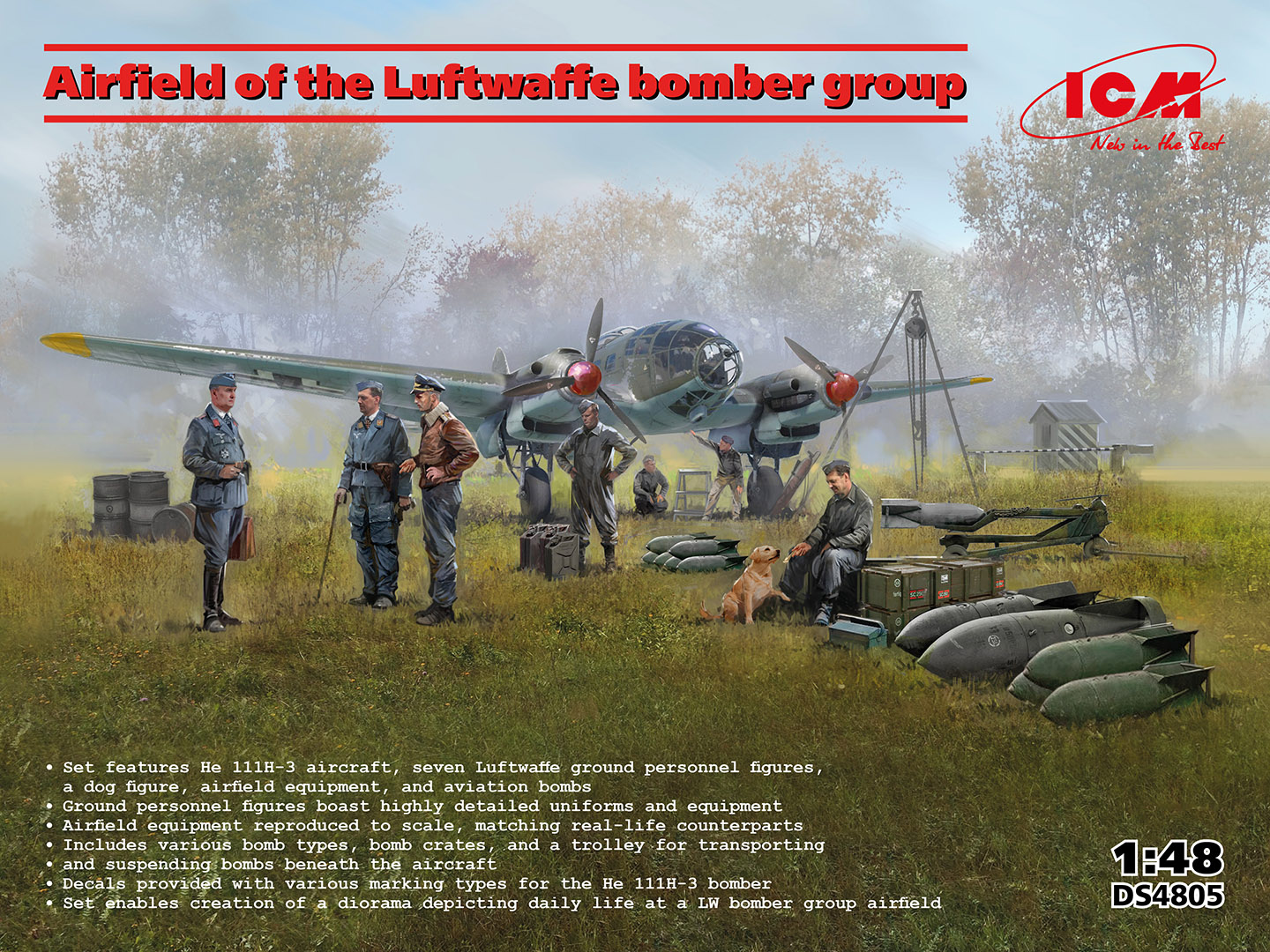
ICM continues their run of “dioramas in a box,” this time by kitting the kits as one; the He‑111H-3 WWII German Bomber (Kit 48261). Luftwaffe airfield equipment (Kit 48409), and German Luftwaffe ground personnel (1939-1945) (Kit 48229).
Background
The He-111 was initially designed as a fast airliner. But the secret Luftwaffe wanted an aircraft that could also be converted to a bomber with minimal adaptation. The first He-111 flew in February 1935. The first incarnations of the He-111 looked nothing like what became an infamous bomber of the Blitz. The He-111A through 111F all had a normal nose and cockpit configuration. Not until the introduction in 1938 of the He-111P did the full glass nose appear.
The He-111H-3 was powered by two, 1,200 HP Jumo 211D-1. The armament consisted of four 7.92 mm MG15’s, two on either side of the waist, one in the rear lower gondola, and one in the upper opening. Different versions had an additional MG 15 in the nose and in the front gondola spot. These two guns could be replaced by 20mm MG FF’s.
What’s in the Box
- 1 large bag with 6 large sprues and one small sprue of gray plastic for the He-111.
- 1 medium bag of clear parts, also for the He-111.
- 1 medium-sized bag with 7 sprues of gray plastic for the airfield equipment.
- I small bag with Luftwaffe pilots and ground crew figures.
- An 8-inch by 11.5-inch instruction booklet for assembly and painting of the HE-111.
- An 8-inch by 11.5-inch instruction booklet for assembly and painting of the airfield equipment.
- An 8-inch by 11.5-inch sheet for assembly and painting for the seven figures.
The Instructions
The instructions consist of a 28-page glossy 8-inch by 11.5-inch instruction booklet. The front cover provides a brief description/history of the aircraft, including technical data, in both Ukrainian and English. ICM paint colors and descriptions of the various pictorial symbols/notes are also on this page. The paint color chart has the color name and letter call-out used in the instructions.
Pages 2 through 4 are the parts maps for the eight sprues of the He-111. Pages 5 through 25 are the assembly instructions for the He-111. The images are sharp and show the assembly as an exploded ¾ view. Page 26 shows the placement of the stencil decals that are common to all versions. It also shows the paint call-outs for the upper surface splinter camouflage and the underside. Finally, pages 27 and 28 are left and right view painting guides for the four decal options included in the kit.
The airfield equipment assembly and painting is covered in a separate 8-page booklet.
A separate two-sided sheet covers the seven figures. One side has a parts map and paint guide. The other side is a combined assembly and painting guide figures. Unfortunately, this is in black and white. Paint call-outs are very busy on the officer figures as each emblem is called out, even though most are not visible on the moldings.
Things to Consider Before Starting
For the He-111, one will need to decide which of the four decal options they want to build, as there are options for guns and gun placement for each option during the assembly.
Also, the bottom aerials are molded to one side of the fuselage. They are very thin and very fragile. I broke them both and lost them to the carpet monster early in the build, and had to scratch-build replacements from styrene rod.
Construction
I start all my builds by scrubbing the sprues with an old toothbrush in warm water and dish soap (Dawn) to remove any residual mold-release residue.
Many parts are scale thin, so use caution when removing these parts as they are prone to breaking or disappearing into the ether if not carefully cut from the sprue.
Cockpit and Interior Details
With a careful review of the instructions for the He-111, one can determine what can be built as sub-assemblies and painted the same color. I assembled most parts in Steps 1 through 41, leaving off parts that were not neutral gray and the glass in the fuselage side and lower gondola. Pre-paint the parts that are not neutral gray. Then, after painting this sub-assembly, go back and attach the pre-painted parts and glass parts. I also left the left and right waist machine guns off until the very end, as the barrels sticking out were just asking to be broken.
Steps 19 through 21 require special care. These parts are scale thin and easily broken both when being removed from the sprue and during handling. Having found that out as the build progressed, I recommend leaving these steps until just before the front glass is installed in Step 98. I found that trying to install some of these parts under the seat was overly difficult. I suggest leaving the seat (Step 17) off until all the parts in Steps 19 through 21 are attached.
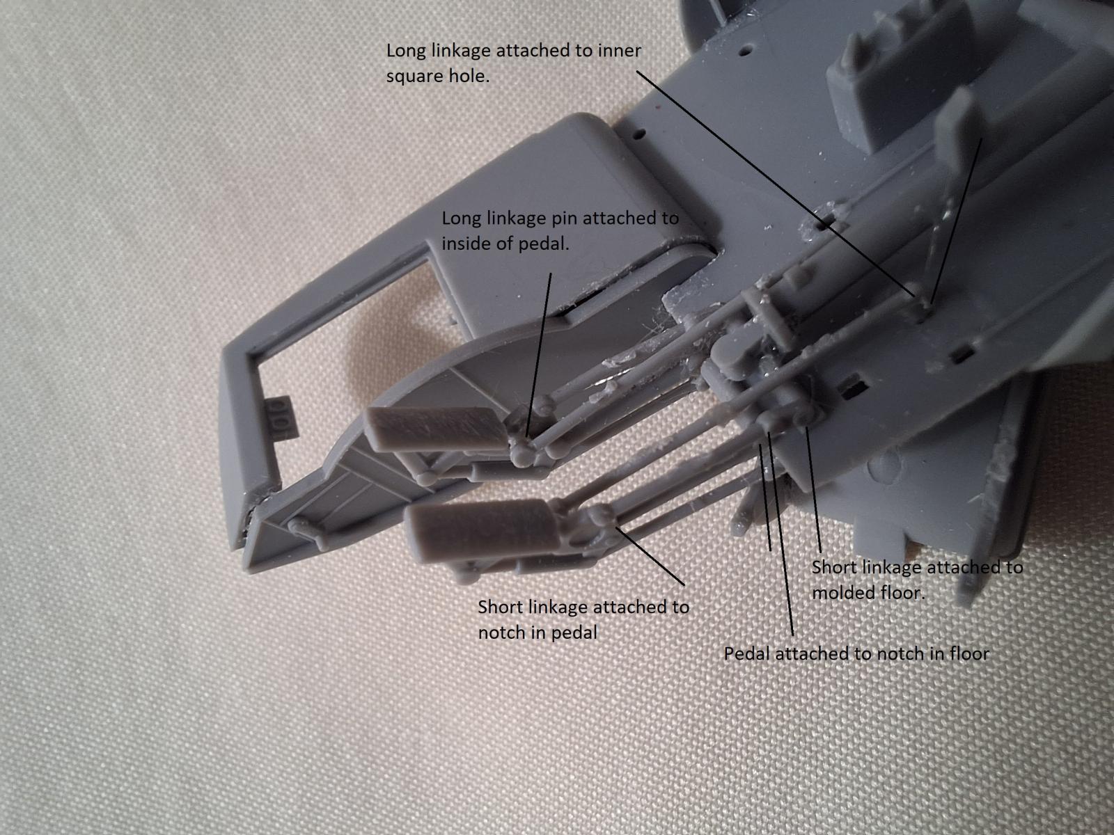
In addition, rather than doing each pedal assembly simultaneously, I did the inside one first, then the outside one as follows. Attach the inner pedal (part D2-24) to the notches in the floor. Attach the inner linkage (part D2-32) to the pedal. The pin on D2-32 fits into a hole on the inside of D2-24. Attach the outer linkage (part D2-36) to the pedal assembly. The pin on this part fits into a hole on the outside of the part D2-24. Now repeat the process for the outer pedal assembly (parts D2-23, D2-31, and D2-37.
NOTE: Parts D2-23 and D2-24 are handed. Take care that the holes on the pedals face each other, and the pins for parts D2-31 and -32 are on the outside.
The instructions are vague as to the attachment locations for these parts. The upper arm on the pedals (parts D2-23 and -24) is notched. This notch attaches to the notch on the top of the floor. The square peg on the rear of parts D2-31 and -32 goes into the rear inside holes beneath the seat. For the smaller linkage (parts D2-36 and -37), the back ends attach to the sides of the half-round bar molded on the floor, while the front has a notch that fits into the notch at the top of the triangular bracket of the pedal.
Assemble all the machine guns in Step 28. But as noted above, leave them off until later in the build. I had trouble attaching the tail wheel assembly in Step 31. The upper part was too short to reach both sides of the fuselage. It ended up falling out after I joined the fuselage halves, so I had to wiggle it into place at the end of the build.
I encountered the same issue in Step 38 as I have in all the ICM aircraft I have built. The inner bulkheads are a few millimeters too wide, so the fuselage halves don’t join well at the front. I used filler to fill the gap.
I again elected to leave the fragile rudder linkages in Steps 43 and 44 off until the end of the build. I also left the permanent attachment of the upper fuselage cover (Step 50) until the end of the build.
Parts A11 and A12 have a large bevel on them. It is easy to see how they attach to the inside of the fuselage. Use extra care when removing parts D2-21, -25, and -28 from the sprue as they are very thin and break easily.
Use magnification for Steps 53 and 54. Parts C6 have small beveled ends that allow them to fit flush with the outside of the bomb fins. In Step 55 I found it easiest to install the center partition (part C42) first and then work out from there. Also note that parts C44 and C45 do NOT have the small nubs on their tops.
Wings
In Step 60 it is critical when attaching the upper wing to ensure that the wing spar fits tightly between the guide slots on the wings. If they do not then the wings will not join and leave a large gap.
Engines
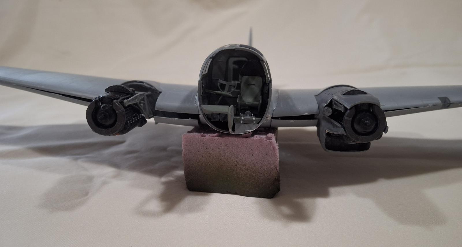
Steps 68 thru 79 are construction of the two Jumo-211D-1 engines. These are real beauties with only the wiring missing. To ease painting, one can assemble the engine supports (Steps 74-77) and attach them to the firewall (Step 80), then attach the completed and painted engines later.
My one negative comment is that the air intake (part C40) is molded solid. I suggest that it be drilled out for better accuracy.
In Step 80 Decal 3 goes on the forward panel of part D2-16. Be careful with this decal as each dial is a separate decal.
Take extra care in Steps 81 and 87 when installing the nacelle side walls. Their installation requires some minor deflection of the engine supports. However, attachment points for the supports are small and fragile. I recommend reversing Steps 86 and 87.
Wings Part 2
The air inlets built in Step 85 fit between the two side panels. Having both side panels in place makes locating the air inlet much easier.
The same care must be used in Step 88 as in Step 60. If the guide slots on the lower wing do not match up exactly with the wing spars, then the wings do not join well. Even using extra care, I found that the wing leading edge outboard of engines and the trailing edges fit perfectly. But the portion inboard of the engine had a large gap and required a real effort to close it.
In Step 90, parts C29 attach to the back of the side panels. The oil cooler radiator sits in the center of this part. The lower cowl panel (part C89) attaches to the rabbit (little ledge) on the front of the radiator air inlets and the side panels.
I Step 92 The upper cowl panels attach to the rabbit on the side panels and top wing, and the back of the front cover (part C24). I found it easier to install all the cowling panels, then attach the front cover (part C24).
I Steps 93 and 94, the upper cowl panels attach to the rabbit on the top cowl panel and over the upper edge of the exhaust side panels.
Cockpit part 2
In Step 95, part E42 is a clear instrument panel. The instructions fail to mention that there is a decal for the instrument panel. Attach the decal to the (flat) back of the panel. After it has set, paint over the back with dark gray.
As noted previously, I did not install the machine guns in Steps 95, 100, 101, 102, 104, and 105 until after painting.
Landing Gear
I assembled the landing gear in Steps 108 and 109 and painted them, before adding in the wheel/tire. Pay attention to which gear is which as they are handed. If they get switched then they do not sit vertically from the wing.
Final Assembly
After painting the upper and lower surfaces, I attached and completed the landing gear assembly (Steps 110, 111, 113, and 114). This was followed by attaching the landing gear and bomb bay doors. I also installed all the machine guns. Then permanently attached the front glass, upper fuselage cover, and windscreen, and all the remaining “fiddly bits.”
Luftwaffe Airfield Equipment
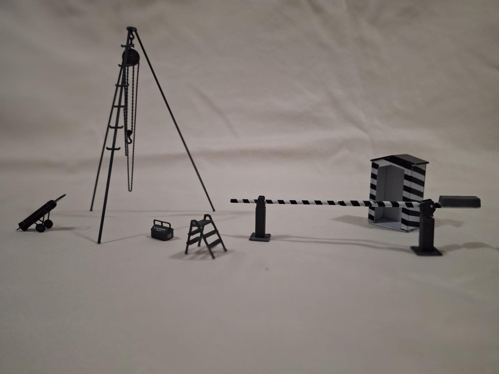
All the airfield equipment was assembled without difficulty. As with many other parts, take extra care assembling the bomb cart, compressed air cylinder cart, and tripod crane, as they are very thin and very fragile.
When assembling the bombs parts W1 attach to the fins facing each other and on opposite sides. So that there is one side with fins that have W1’s, one side with nothing, another side with two W1’s, and the fourth side with nothing.
For the SD250 Jb bombs, parts W1 and the fuse extender (parts W2 and W22) are optional. For the SC500 J bombs, use the same care as with the bombs for the He-111, as parts W24 have beveled ends that allow them to sit flush with the outside of the fins.
Luftwaffe Pilots and Ground Crew
Assembly of the crew figures is straightforward. Note that the figure with the cane and the one with his hand on his hip have optional hats and heads, respectively.
Painting and Finish
After assembling all the interior parts in Steps 1 through 41, I primed the interior assembly with Krylon Fusion All-In-One paint and primer Matte Glacier Gray. I allowed this to cure for 48-hours.
After doing some research, I learned that the interior behind the cockpit was one color of gray and the cockpit was a darker gray. Using an airbrush, I sprayed the rear interior and landing gear bays with Model Master Acryl (4077) Grau RLM02. I sprayed the cockpit with Tamiya XF22 RLM Gray. I also assembled the two bomb racks, engine support brackets, and landing gear, primed them, and painted them with Model Master Acryl Grau RLM02. The insides of all the cowl parts, landing gear and bomb bay doors, and tail wheel and compartment were also all sprayed with Model Master Acryl Grau RLM02.
For parts called out as black, I used Tamiya XF-17 Flat Black. The tail wheel tire and main tires were painted with Tamiya XF-85 Rubber Black. Parts called out as gun metal were painted with Tamiya Gun Metal (X-10). For dark rust I used Life Color LC38 Matt Rust2, and natural steel was done with Mission Models Cold Rolled Steel (MMM-002).
The engine was assembled (Step 68) then primed the Matte Glacier Gray and airbrushed with Tamiya Semi-gloss Black (X-18). All remaining parts were primed with the same Matte Glacier Gray while on the sprue.
The landing lights notch on the left wing was painted with Mission Models Aluminum (MMM‑003) after the top and undersides were painted.
Before painting the upper and lower surfaces, I used Elmer’s white glue to temporarily attach the front cockpit, the lower gondola front (part E5/E6), and rear E3, and the top fuselage cover and windscreen. I also used soft foam inserted into the tail and main wheel wells, upper gun position opening, and bomb bay openings to seal them.
Given the extensive glass on this model, a masking set is, for all practical purposes, essential. I used the masking set EX580 from Eduard. This set is made for 1/48 ICM He-111H-3. After about a half a day of applying masks to the model, it was ready for painting.
The first step was to prime the whole aircraft with Krylon Fusion All-In-One paint and primer Matte Glacier Gray. This was allowed for cure for 48-hours.
All four schemes have the early war splinter camouflage of RLM 70 Schwarzgrun (black green), RLM 71 Dunkel Grun (dark green) over RLM 65 Hellblau (light blue). In the painting guide the dark green is called out as German Field Gray, the black green is called out as extra dark green, and the light blue is called out as blue gray. I went with RLM colors using Model Master Acryl (2078) Hellblau RLM 65 for the light blue underside, AK Real Color RC274 RLM70 for the black green, and Vallejo Model Air 71.015 dark green RLM71.
Following priming, the bottom of the fuselage, wings, engine nacelles, and elevators were airbrushed Model Master Enamel (2078) Hellblau RLM65. This was allowed to dry for 24 hours before masking the demarcation line with Tamiya masking tape and filling in the larger areas with 3M blue painters tape.
I enlarged the overhead view on page 26 to 1/48 and cut out the different patterns to use as paper masks. The edges of the extra dark green (black green) were masked off with Tamiya tape for a hard demarcation line. The paper masks for the extra dark green (black green) were cut slightly smaller and used to fill in between the tape masks.
I then airbrushed the extra dark green (black green) using Vallejo Model Air 71.015 dark green RLM71. This layer was allowed to set until dry to the touch, and then I removed the masks and tape. After removing the masks, the paint was allowed to cure for a day. Next, I masked the extra dark green with more Tamiya tape and filled in with the German field gray paper masks that were cut to size. I then airbrushed the German field gray using AK Real Color RC274 RLM70. When dry to the touch, I removed the tape for the masks, the demarcation line, and all the window masks.
The propellers were painted Extra Dark Green (Vallejo Model Color 70.896). Since I chose Option 2 with the deep blue spinners, I used Tamiya X-4 Blue for the spinners and spinner backplates.
Airfield Equipment
Almost all of the airfield equipment has the option to be painted Dark Gray or German Field Gray. The bomb crates have the option of being German Field Gray or Extra Dark Green. The 50 kg bombs can be either German Field Gray or Ochre, while the larger bombs add the option to be pale blue to the above two colors.
Even though this set depicts an early war airfield, don’t be afraid to mix and match equipment and bomb colors. I painted the equipment Dark Gray using Tamiya XF-63 German Gray. There are three each of the different bomb crates. I painted the two crates, each for the SC bombs, Extra Dark Green using Vallejo Model Color Extra Dark Green (70.896), and one crate size each with Tamiya XF-63 German Gray for the dark gray.
I used the same colors for the bombs. I also painted some of the larger bombs Model Master Acryl Hellblau (2078). I painted a few of the SD50 Stg bombs with Lifecolor UA 081 Sand Yellow RLM79 for the ochre.
Figures
Figures were painted following the painting guide. I used the following colors:
- White = Tamiya X-1 Flat white
- Black = Tamiya Semi-gloss Black (X-18) for boots, Tamiya NATO Black (XF-69) for uniforms
- Dark Blue = Tamiya Sea Blue (XF-17)
- Tan Earth = NATO Brown (XF-68)
- Deep Blue = Polly Scale US Sea Blue (505092)
- Chocolate (Chipping) = Tamiya Hull Red
- Deep Yellow = Life Color Yellow (UA 140)
- Silver = Vallejo Model Air Silver (70.997)
- Brass = Model Master Acryl Brass (4627)
- Natural Steel = Mission Models Cold Rolled Steel (MMM-002)
- Basic Skin Tone = see below
- Light Earth = Life Color Sand Yellow (UA 081)
- Neutral Grey = Model Master Acryl Grau RLM02 (4770)
- Matt Red = Tamiya Flat Red (XF-7)
I painted the figures from the lightest color to the darkest. This meant starting with painting the flesh areas Model Master Acryl Skin Tone Warm Tint (4603). When dry to the touch, I used a wash made from Model Master Acryl Skin Tone Shadow Tint (4604). The final step was to create highlights by dry brushing Tamiya Flat Flesh (XF-15).
Decals
The decals are well-printed and opaque. They are however, very thin, making them equally very fragile. I also found the longer decals prone to folding over on themselves. Being thin and fragile, unfolding them is almost impossible without breaking/tearing them. I also found that they required more than the normal time in warm water before they could be slid off the backing paper, upwards of 20 to 30 seconds. The larger decals are easy to tell when they are ready, as they will curl when placed in the water and then slowly flatten out. I found that all decals reacted well to Microscales Micro Set and settled in well with Micro Solv.
For the guard shack and the traffic arm, the black stripes are supplied as decals. While this is a great idea, eliminating a lot of what would be long and difficult masking, the decals are fragile. I had a couple of the stripe decals for the guard shack fold and/or tear. When doing the traffic gate arm, pay attention to decal placement so that the decal seam ends up on the bottom of the gate arm.
Be careful when decaling the bomb crates, as the different types have some common decals.
Conclusion
I recommend this kit for advanced intermediate to experienced modelers. The build is straightforward forward but there are a number of very small and very fragile parts to deal with. In addition, the tight tolerances require extra care to ensure that joints, such as the fuselage, wings, and wing roots, fit tightly.
By carefully reviewing the assembly sequence laid out in the instructions, it is easy to see where sub-assemblies can be created to help with painting. The thin and fragile decals also require careful handling.
I would like to thank ICM for providing this kit for review, and IPMS/USA for giving me the opportunity to build it.


Comments
Add new comment
This site is protected by reCAPTCHA and the Google Privacy Policy and Terms of Service apply.
Similar Reviews