
USS Midway Pt 3: Flight Deck and Island
Intro
This last part has only 2 key elements really, the flight deck and the island. However, there are a lot of individual steps that make this as long as the other 2 parts of the ship already completed (hull and hangar bay). The fine details really come together around the flight deck. Take note of the order in which you want to handle the assembly. For instance, doing some of the PE on the flight deck would be best done before attaching the island so you can flip the carrier over for ease of assembly. With that, let’s head for our home port...
Flight Deck
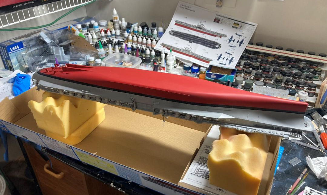
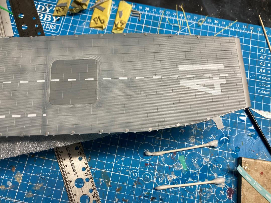
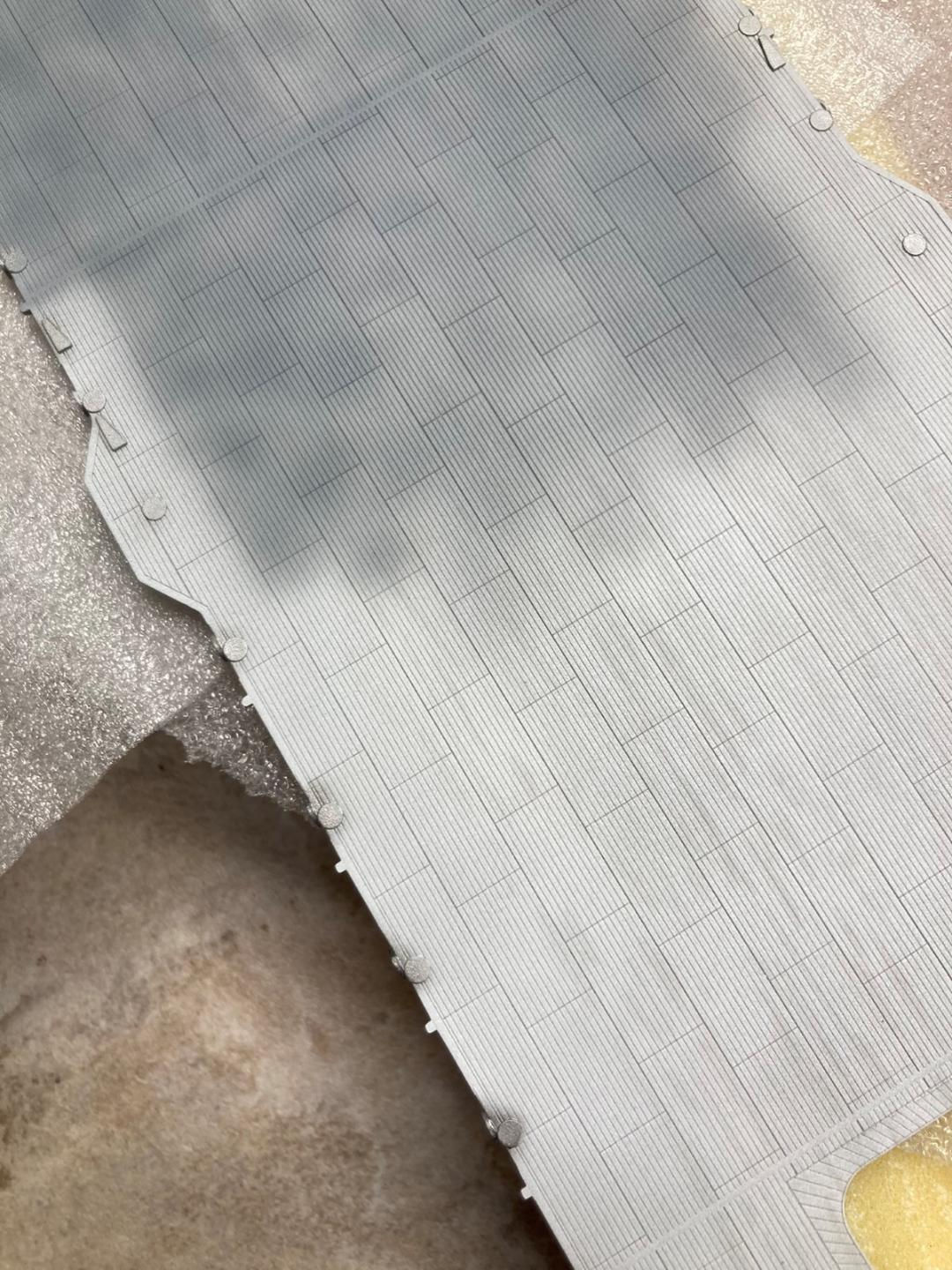
The real story here has to be the fit. Two perspectives drive that conclusion, 1st is that after all those individual hangar bay walls were fit and glued in days ahead of time everything aligned perfectly and 2nd is that the elevators in the deck are a snug fit around the whole circumference with just some minor sanding so they would slip in. The biggest debate amongst modelers is probably going to be the depth of the grooves to represent the steel deck. Photos of the real thing definitely show the demarcation lines, it’s just that the deck is flush so there’s some give and take here to create something visual on a model. Given the lines are visible on the real carrier you can create stronger or lighter demarcation lines with the extent of weathering that is done.
There are some large ejector pin marks on the underside of bow and stern flight deck. If you aren’t entering a competition these are well hidden and there’s no need to fill them. If you are planning to put it on a table then the 3 in the bow and the 2 on the outmost edge on the stern need filled. There’s also a pair on either side of the port elevator that will need filled as well.
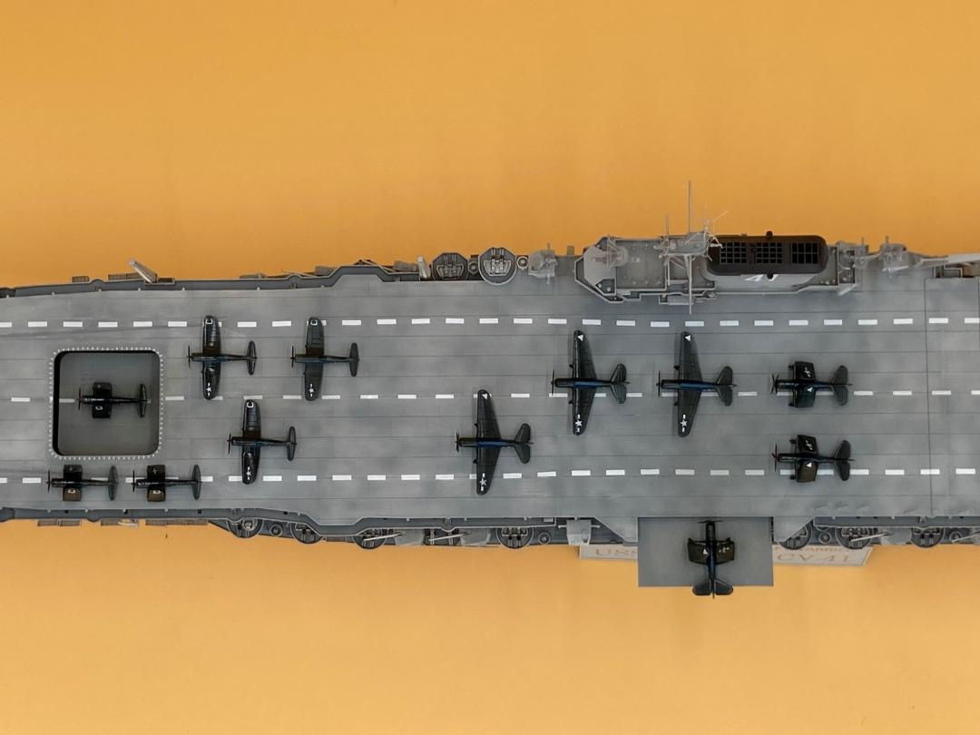
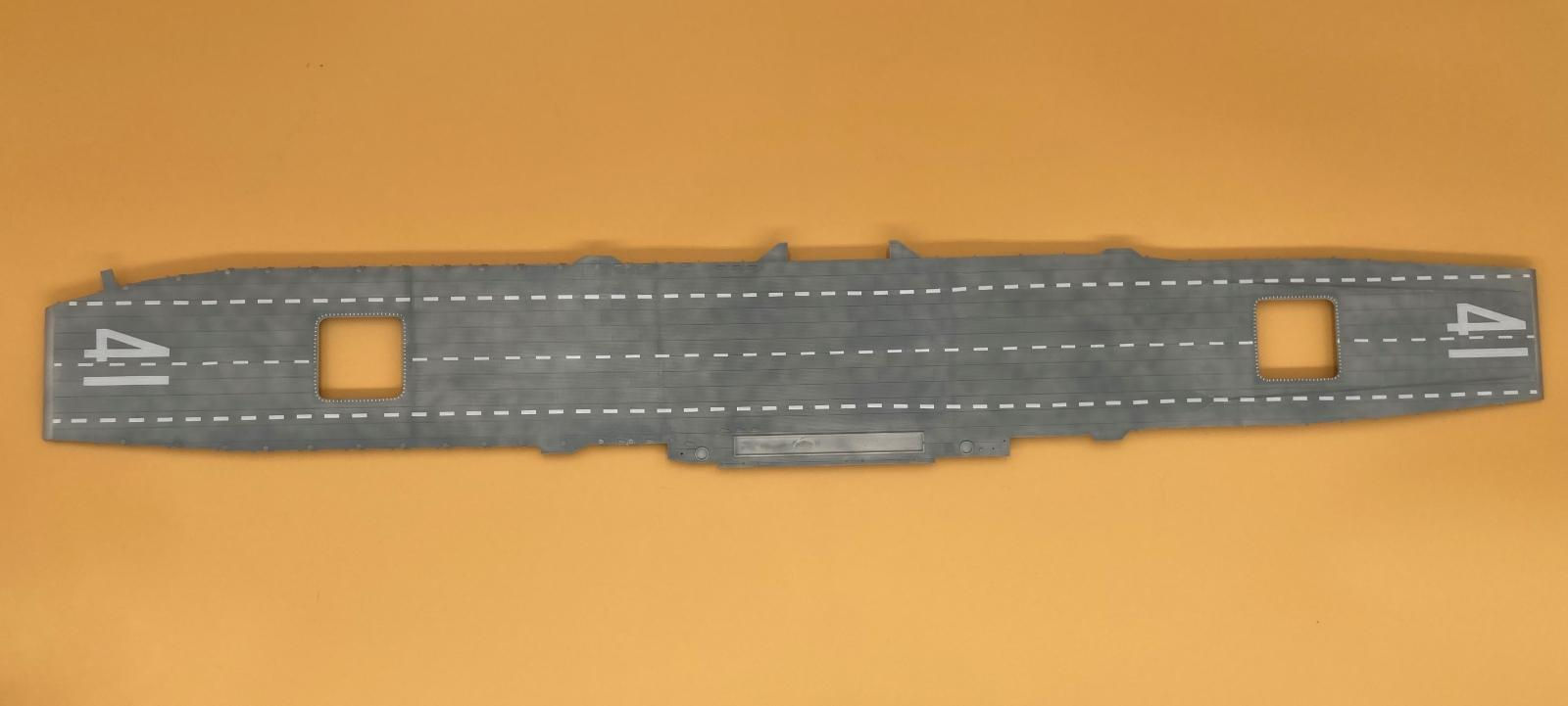
The watch out here is with the decals. The grooves are deep enough that the decals will tear if you try to mold them to the deck rather than wait for the solvaset to melt them to the deck. Overall the decals responded very well and look dang close to being painted on. I chose to separate the 4 and the 1 so there wasn’t a large section of clear film in all those grooves between numbers. The decals lay down and mold right to the deck in this fashion.
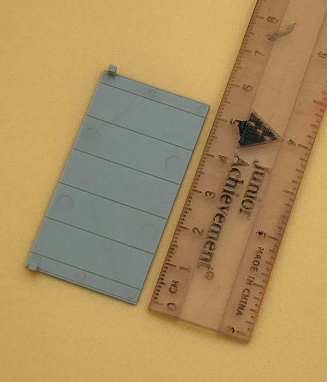
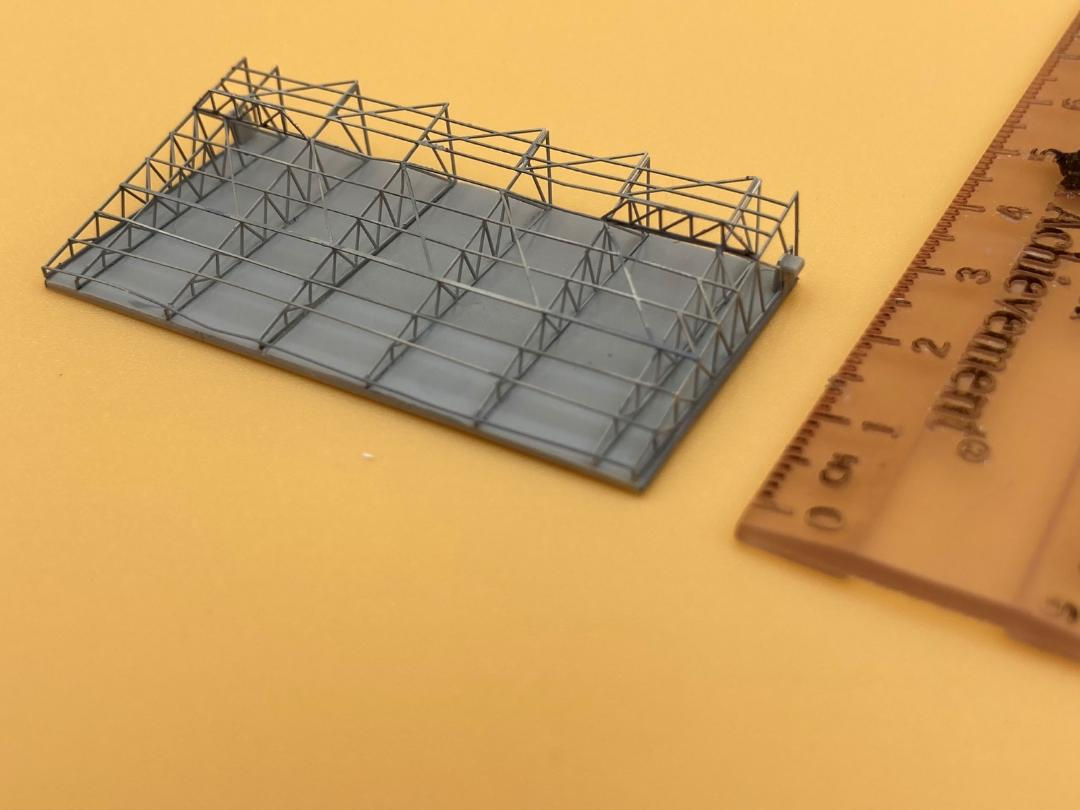
The flight deck elevator on the port side builds up well. There are fine grooves underneath for the photoetch to rest in, making this a solid piece that can be moved around during painting without too much risk of breaking pieces off. No fit issues here either, plus it can be posed in any position on the tracks.
I chose to pose the bow flight deck elevator in transition between decks because the kit includes walls on 3 sides similar to the real carrier. My advice for the decals is to cut them into 2 pieces, along the diagonal. They fit exactly around the edge with no room to spare so if they fold up trying to take them off the paper as a single piece it will be hard to recover from that. Again, they laid down perfectly and look painted on the deck.
Island
This injected molded elements go together cleanly and without issue. There are some crisp raised details around the stack that will show well with a pin wash. The walkways go into place without needing any putty to fill voids. The island itself also fits cleanly to the deck, needing no putty. The value here was not having to touchup the paint or having to assemble this all first, prior to doing any painting or decals on the deck.
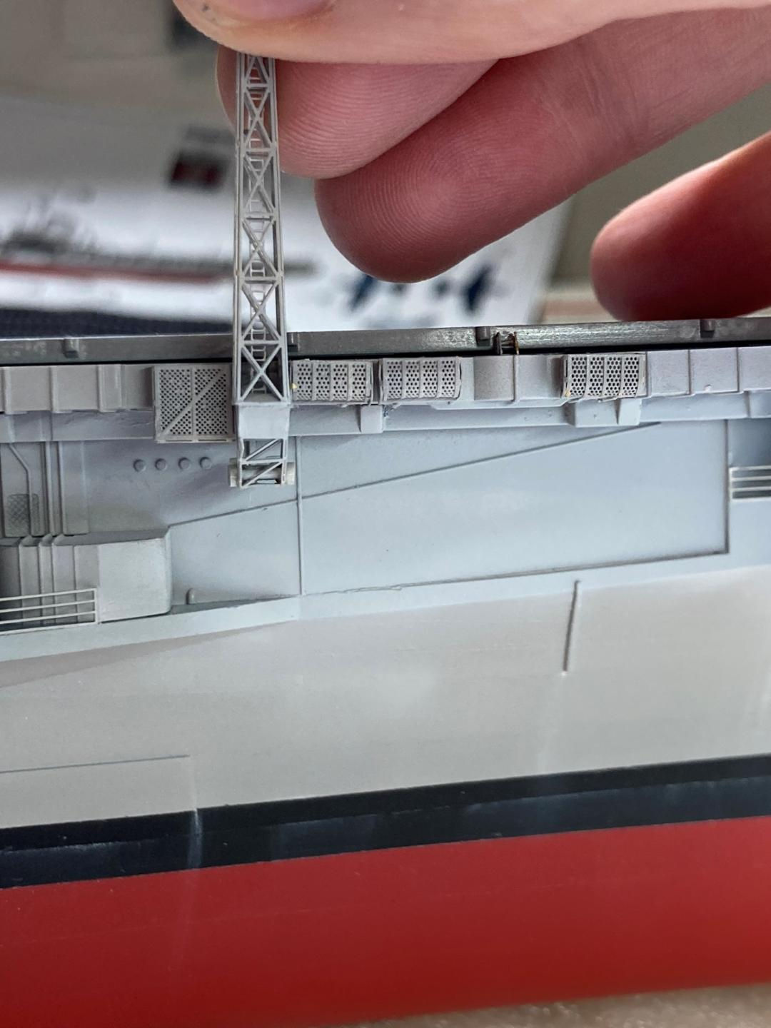
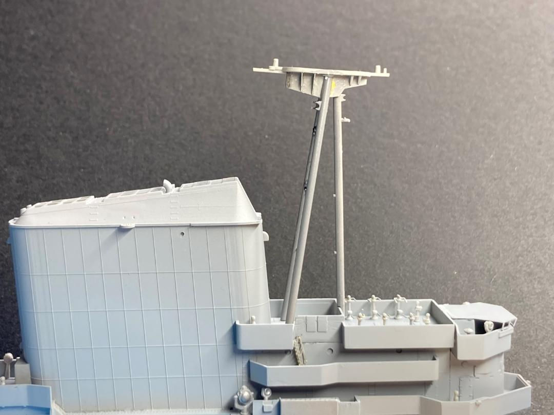
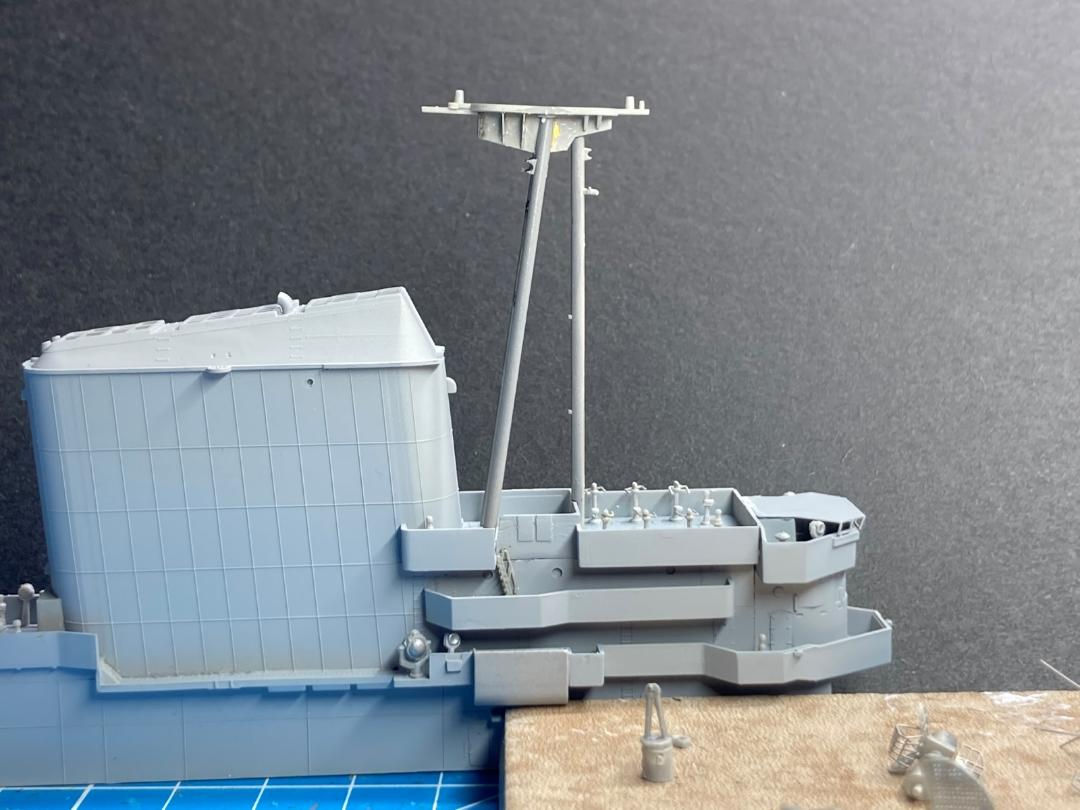
The major challenge came with the tripod mast. Try as I might, I couldn’t get it to line up using the connection points set into the plastic walkway/deck elements. I’ve included a picture “as-built” and then separated for effect. If I were doing this a 3rd time I would tape the front tripod support to the bridge, then add the rear supports and fit the deck to them last. Glue it in place to hold the tripod masts in position and then remove the assembly to install the railings. An important heads-up for the internally mounted railings, they have to be bent in 3-dimensions. There is a curve around each mast plus, the railing has to be angled inward to match the angle of the masts. Quite difficult to do so you will want to make sure the tripod is complete before attempting this as these railings can’t be bent multiple times without coming apart.
On the port side, 2nd deck level, there is an extension of the bridge that is a photoetch assembly (I’m not exactly sure what it is called specifically). There are multiple contact points and it will need trimmed to fit up without causing a gap between the walkway and the island. Similarly, the bridge roof photoetch needed trimmed slightly for a clean fit. Nothing out of the ordinary here, just a few watch-out for the discerning modeler.
Photoetch and Miscellaneous
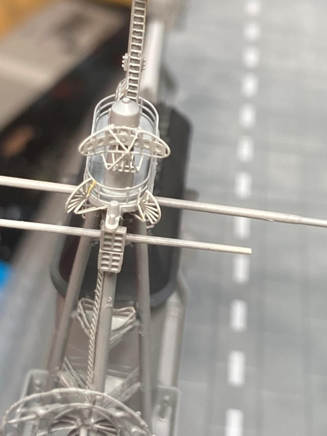
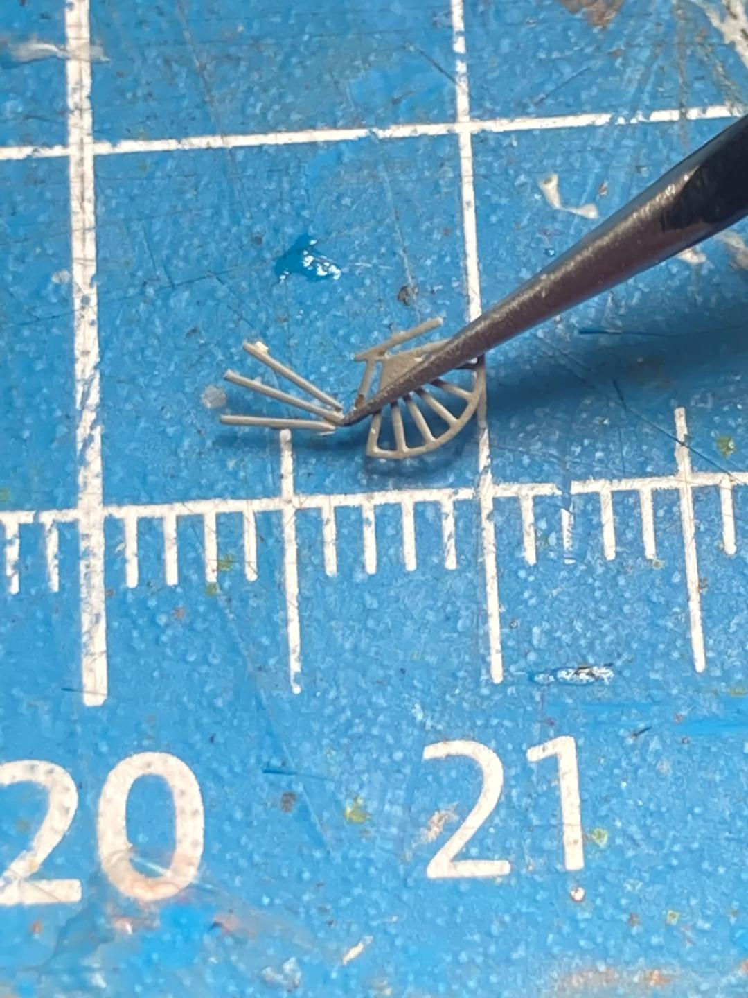
As much as I love the photoetch itself the directions for the folds are severely lacking when it comes to anything more complicated then a 90 degree bend. There are some very fine antennas mounted to the stack and the island; beautiful pieces and I got them all bent and installed perfectly, except I never could find a good picture of the bend so I made a tripod out of the pieces and mounted them in the most logical manner I could. I figured out the stern radar antenna looking at pictures in later views of the island in the instructions. Pay close attention to this as there are small side rails that must be bent right the 1st time or risk them breaking away. The antenna atop the main mast gets mounted to the side of the main mast, but there has to be a fine gap, I figured that out looking at multiple views in different steps of the instructions plus the color slip sheet Trumpeter includes to promote the photoetch in the kit (this turns out to be a good reference for some of the folds).
PE-B29 for the forward antenna has the best instructions. The two options for the radar are clear, and the assembly of the different elements is laid out in chronological order. When assembling PE-B30 and B31 make sure the finished part sits flat and all 4 corner points touch your mat. This will make the rest of the assembly go smoothly.
PE-D9 is still a mystery to me. The ladder goes next to the port elevator, however, there seems to be no location marking and the instructions show a side view such that the ladder looks like a toothpick. I couldn’t find a picture of the real thing so placed it in a logical spot.
Before attaching the island there are a couple pieces of photoetch that should be applied with the carrier sitting on the flight deck for ease of assembly. The two bow walkways, PE-B13 and 14, plus the bow netting on the port and starboard sides would be best fit up near the end of the build to avoid knocking them off.
All the ladders and the 4 large aerials folded nicely and fit well. Railings were the right length and the bends fit up at the stanchions so they look correct. The mounts for the gun directors add to the pieces as plastic would have looked so out of scale.
Home Port
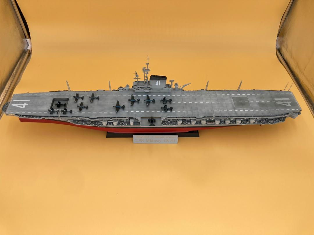
The completed model is a great showpiece! Overall, I spent 3 months building the kit. I spent a couple hours in the evenings during the week and a couple devoted Saturdays and Sundays on assembly and painting. The fit and lack of a need for putty make the build enjoyable. You’ll have the typical time with photoetch, take your time and look for as many references as possible to complete it. These fine details really add to the finished look of Trumpeter’s USS Midway CV-41 model. A huge shout-out to MRC for providing the kit to the IPMS Reviewer Corps! Thank you so much for this opportunity.


1 Starboard

2- Starboard Stern

3 Starboard Bow

4 Port Stern

5 Port Bow

6 Port

7 Aircraft 1

8 Aircraft 2

9 Aircraft 3
10 Aircraft
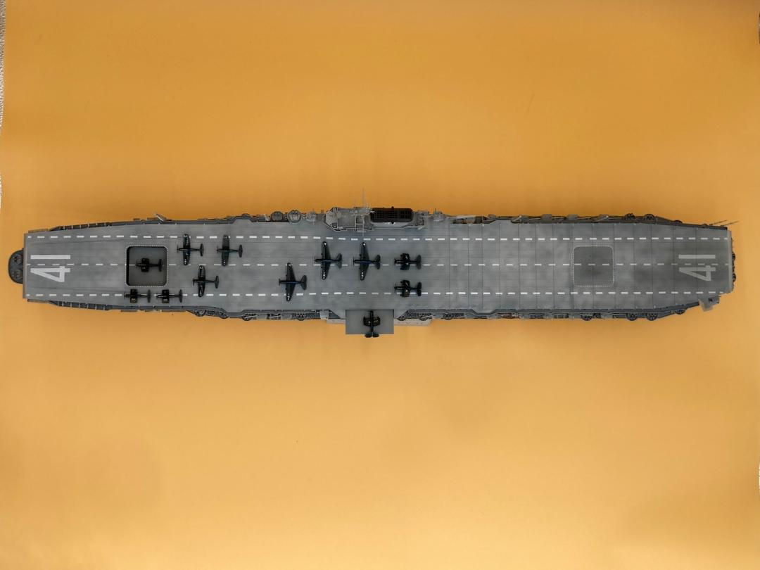
11 Top View
12 Top Angle
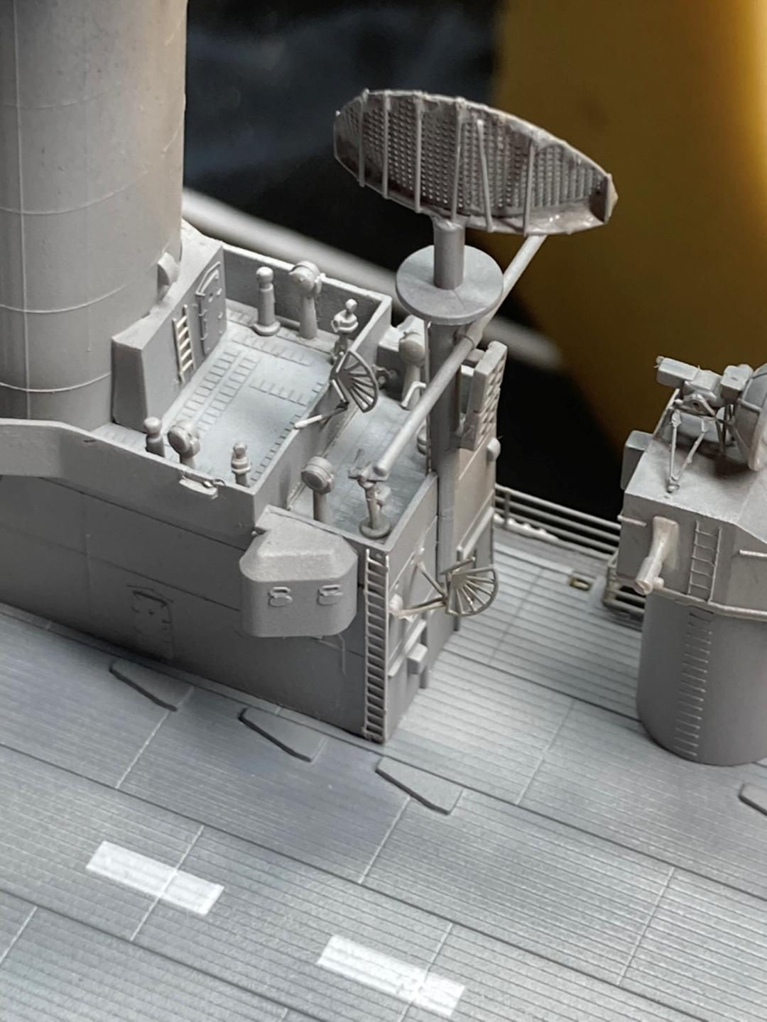
13 Fan Antennae
14 Fan Antennae 2
15 Fan Antennae 3
16 Aerial Antennae
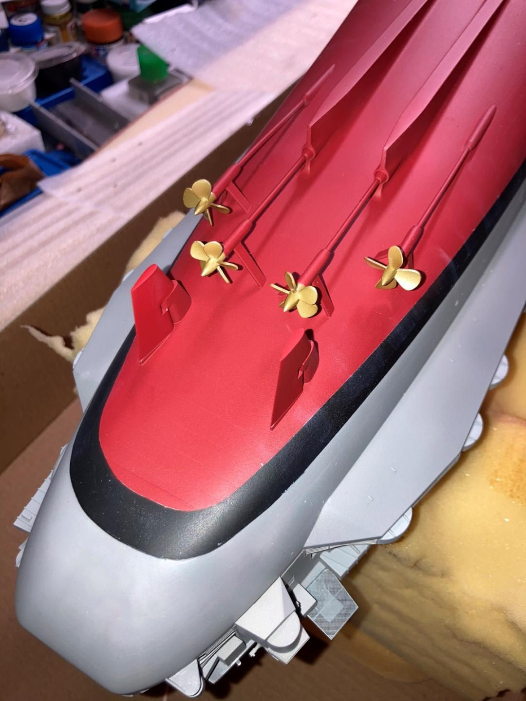
17 Props
18 Hull
19 Tripod Antennae
20 Tripod Straight

21 Elevator Ejector Pin

22 Deck Centerline
23 Deck
24 Elevator
25 Deck Panel Lines

26 Deck Ejector Pins

27 Bow Ejector Pin
28 Elevator Pins
29 Elevator PE
Reviewer Bio
Chris Vandegrift

When Chris isn't modeling he's restoring old cars or doing home remodeling in his spare time. Both have helped improve his modeling. "Having learned to paint cars, quite a few of those techniques apply to priming and painting my models," he says. Chris used to build aircraft exclusively, but has expanded into ships, science fiction, armor and cars. A member of multiple IPMS clubs in Ohio including Akron's Ed Kinney Chapter, Wright Field and Cincinnati Scale Modelers, Chris started building models when he was about 7. Chris lives in Cincinnati Ohio; a Mechanical Engineer by trade, he's the head of Operations and Engineering for a company that makes pumps. He's been married to his wife Jane for 30 years; they have four kids ranging from 20 to 34.
Comments
Add new comment
This site is protected by reCAPTCHA and the Google Privacy Policy and Terms of Service apply.
Similar Reviews