
LFG Roland D.II
Recent advances in 3D design and printing have made it much easier for new kit manufacturers to enter the market with subjects usually avoided by traditional manufacturers. A good example of this is MDesign of Bulgaria. MDesign produces 3D-printed kits of unusual WWI subjects in a variety of scales. In this review I will be examining their new 1/32nd scale kit of the LFG Roland D.II. The Roland D.II was an attempt to develop a fighter from the successful Roland C.II two-seater reconnaissance aircraft. The D.II was not a success, it couldn’t match the performance of contemporary Albatros fighters and was more difficult to fly. The Roland D.II had a very short service life with Germany on the Western Front. The Roland D.II had a much longer career in Bulgarian service.
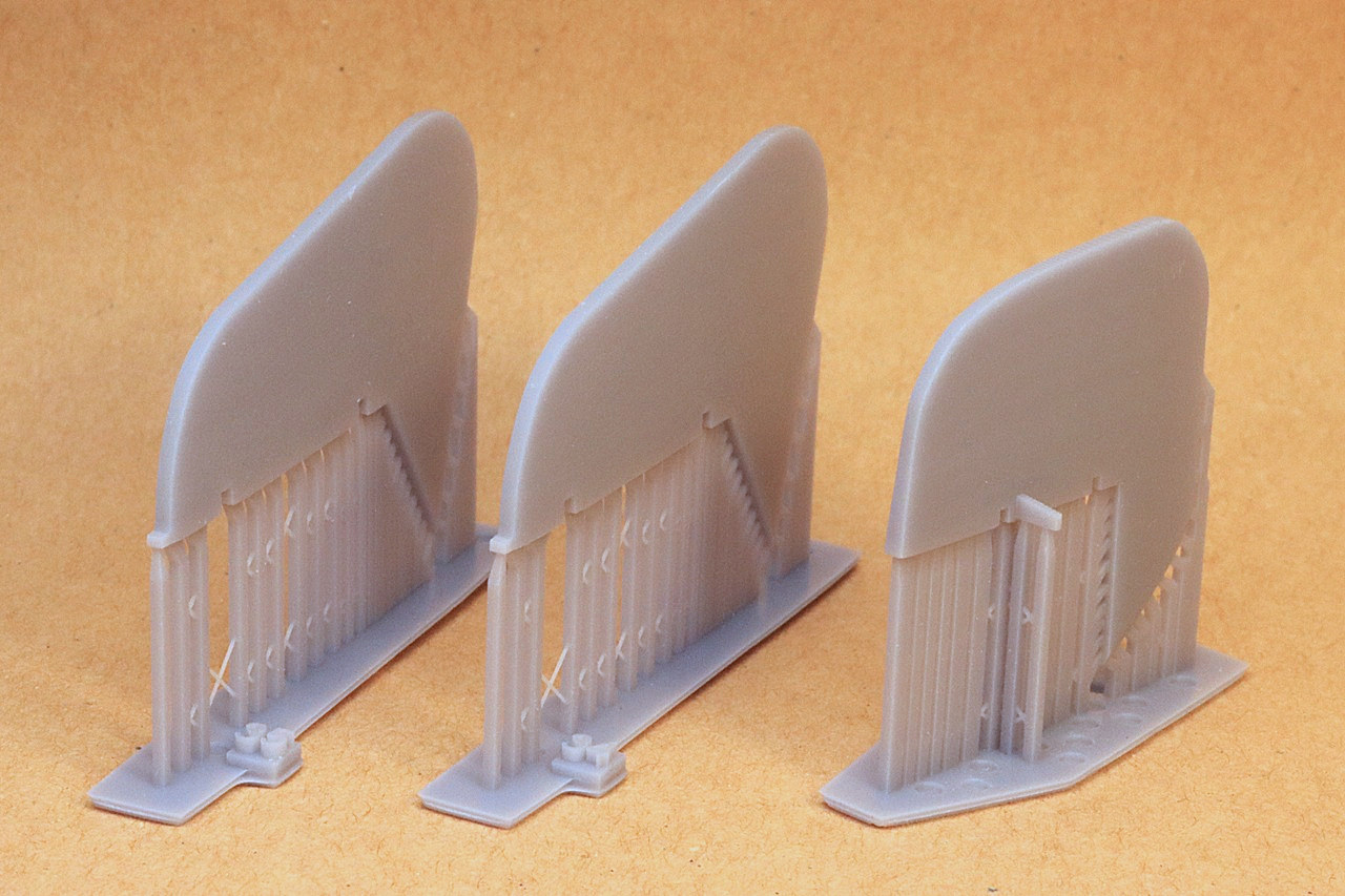
The kit comes packed in a sturdy hinged-top cardboard box. The 3D-printed parts are protected inside bubble-wrap envelopes. Also included in the kit are: steel wires to reinforce and align the wing and horizontal stabilizer joints, pre-cut vinyl masks, a small sheet of decals, and instructions. There are quite a few areas on the kit parts where printing layers will be visible after the first coat of primer. I am not very knowledgeable about 3D printing, but I wonder if this is due to a compromise between quality of finish and the extended printing time required for producing large parts in quantity. Be prepared for some repetition of priming, wet-sanding and re-priming.
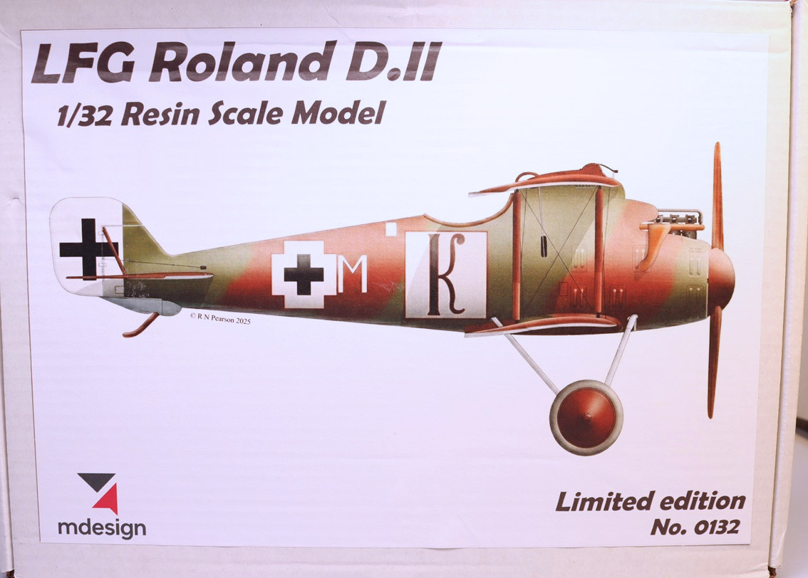
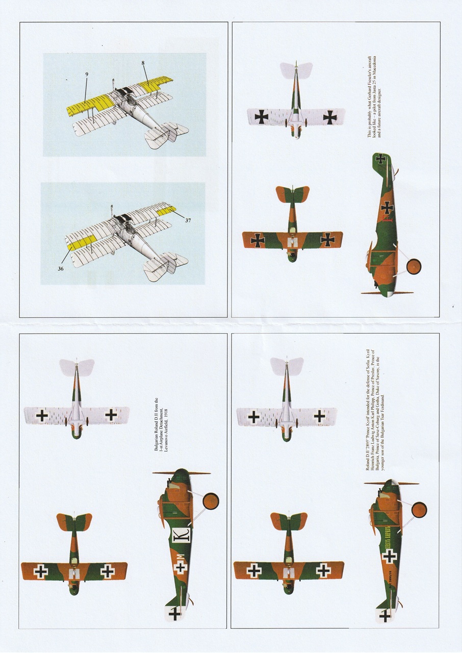
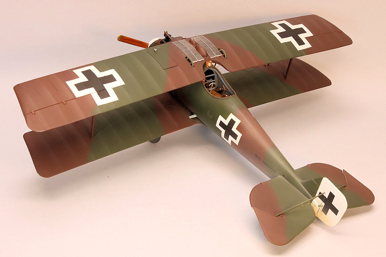
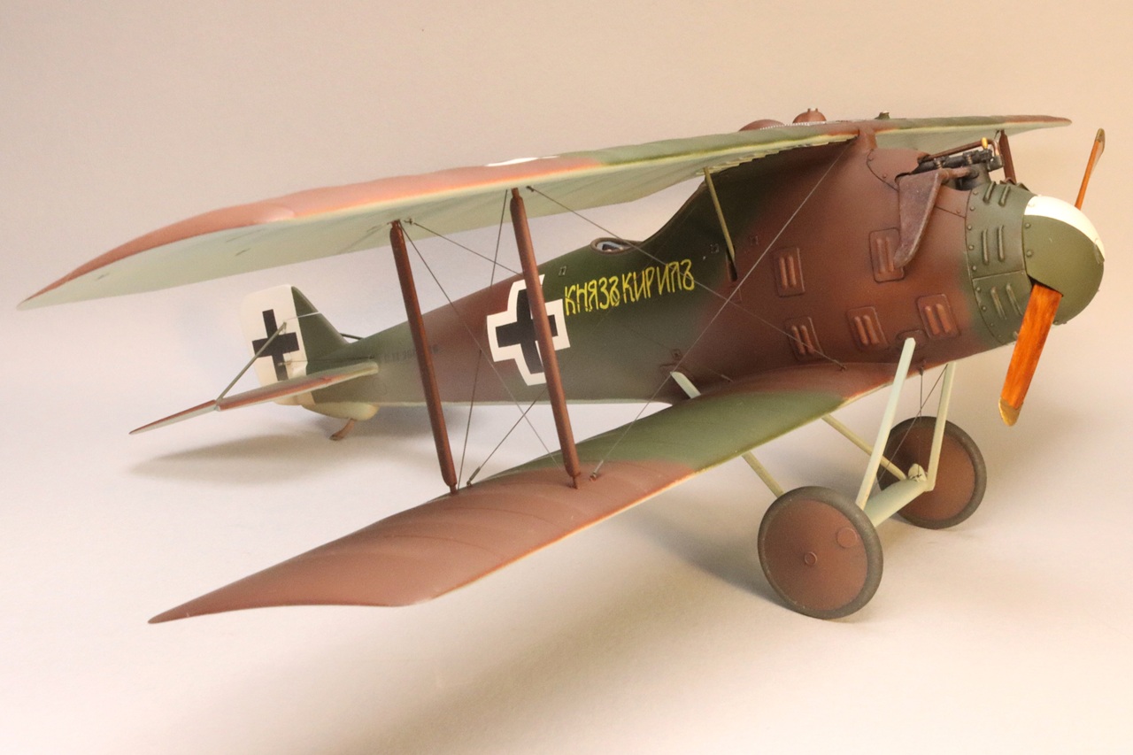
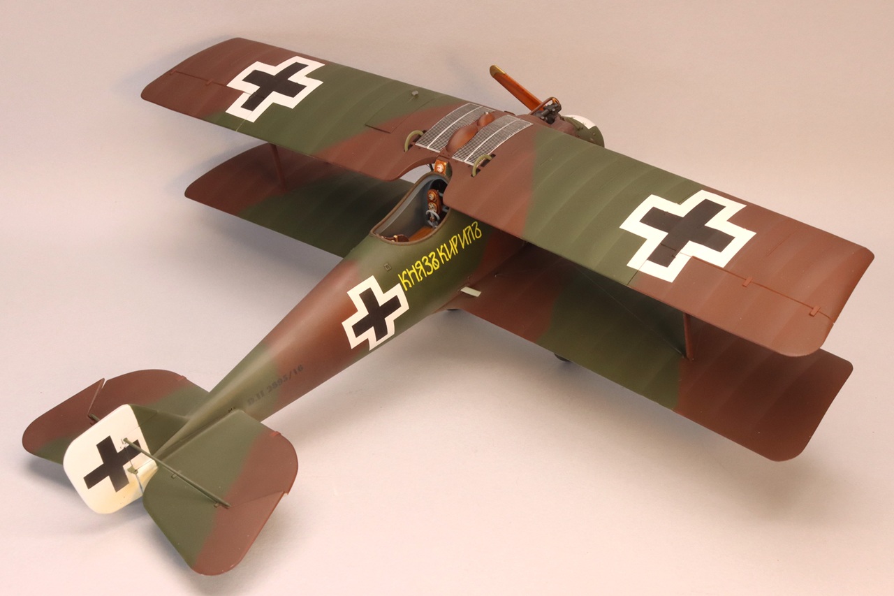
There are three marking options provided: a Bulgarian D.II from the 1st Airplane Detachment, Levunovo 1918, D.II ‘2895’ the mount of Prince Kyril of Bulgaria, and the mount of Gerhard Fiesler, Jasta 25 in Macedonia.
Instructions
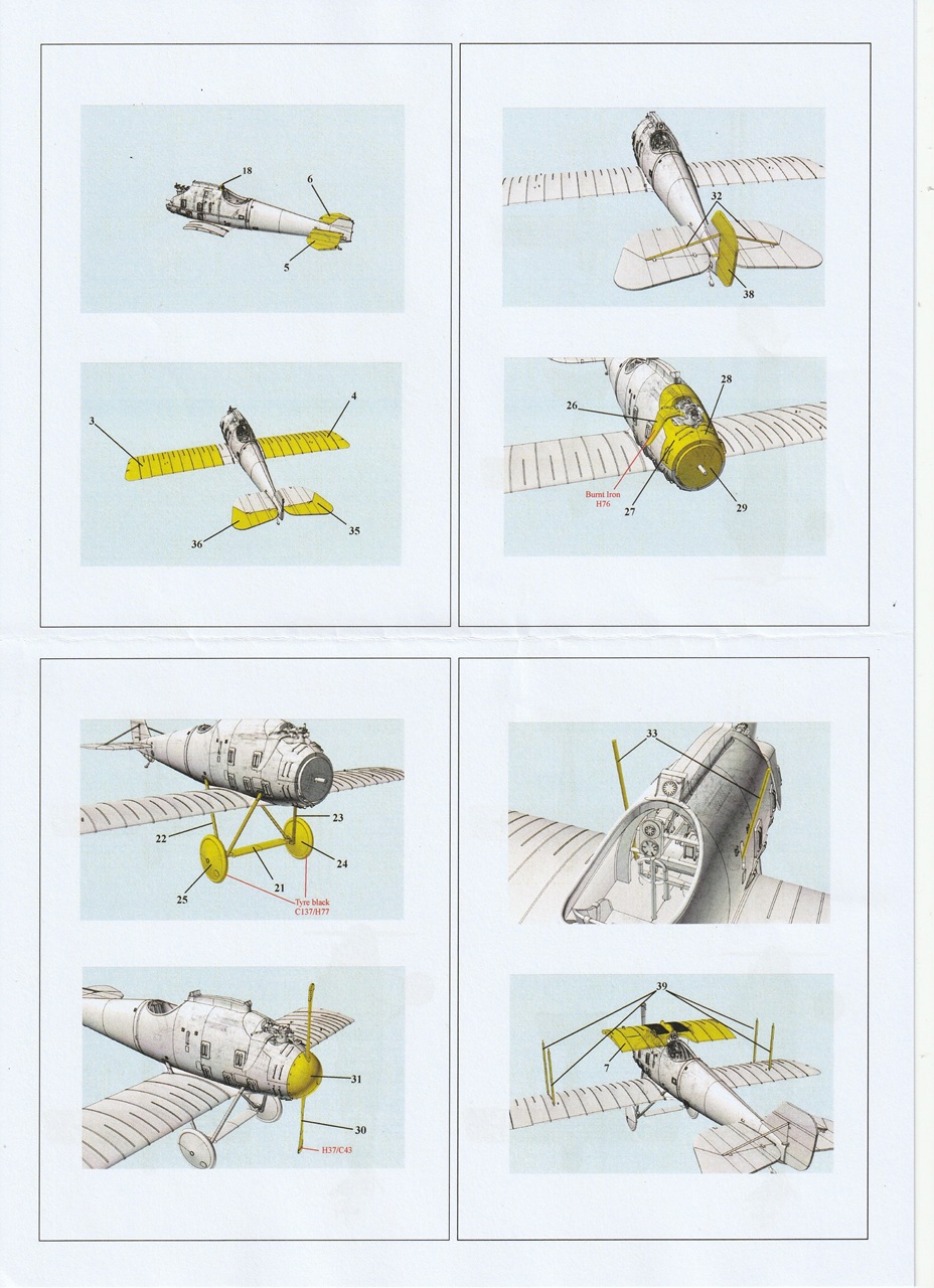
The instructions have small illustrations that show parts in their final locations. These illustrations are adequate, but larger illustrations would have been easier to use. The instructions don’t include any diagrams for installing rigging wires. The Roland D.II is an obscure aircraft and not well documented. The best reference that I know of is Windsock Datafile #47. This is a good reference for the rigging wires and external details but has no photos for cockpit details. Color call-outs are for Gunze Aqueous and Mr. Color paints. Note- I QR code for downloading a high-resolution PDF of the instruction sheet. I could have downloaded the instruction and printed them at a larger size. Oooops
Cockpit
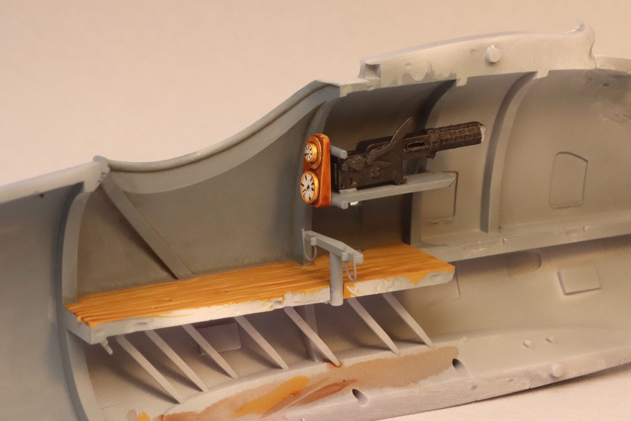
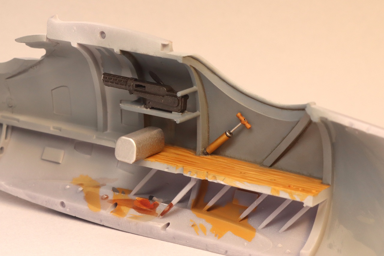
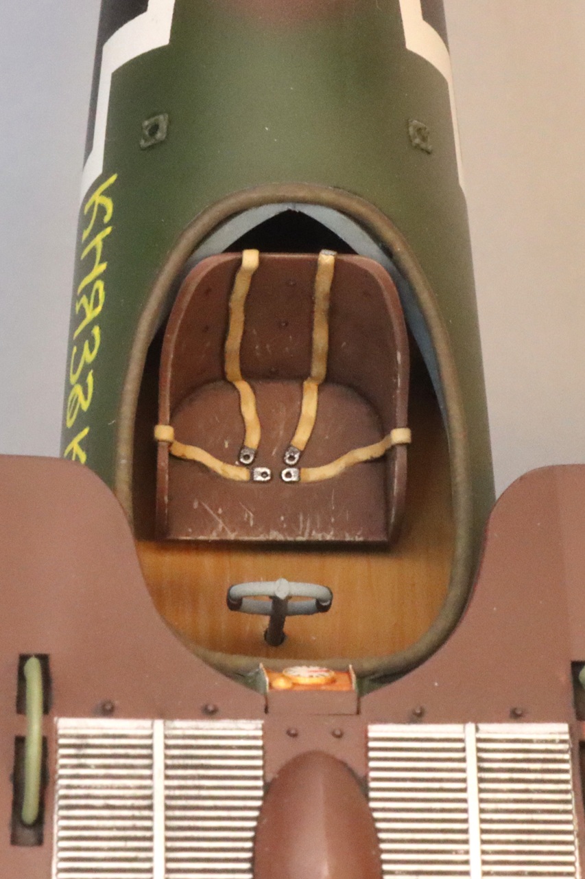
Not surprisingly, construction begins with the cockpit. Be careful cutting away print supports from the cockpit interior. There are thin cylindrical supports for the gun platforms and instrument panels that are easily broken. The gun support structure and cockpit floor are printed in halves attached to each fuselage side. I would have preferred these parts to be printed separately for easier part clean-up and to avoid seams in the center of the cockpit. Part numbers 15 and 10 have their numbers reversed in the instructions. There are no location aids for the fuel hand pump (part #15). I estimated its location based on the illustration. I broke my fuel pump and had to scratch-build a replacement from brass tube, wire, and plastic rod. The seat has the safety harness printed in place. The straps seem thin and the buckles simplified, but I am no expert on 100-year-old Bulgarian safety gear. The rudder pedal bar has very thin foot straps printed in place. One of the straps was broken in my kit, so I replaced the straps with thin pieces of copper wire. The port side of the cockpit where I would expect the engine controls to be, has no detail other than the internal frames. You may want to copy details found in other WWI kits to busy-up the port side of the cockpit.
Motor
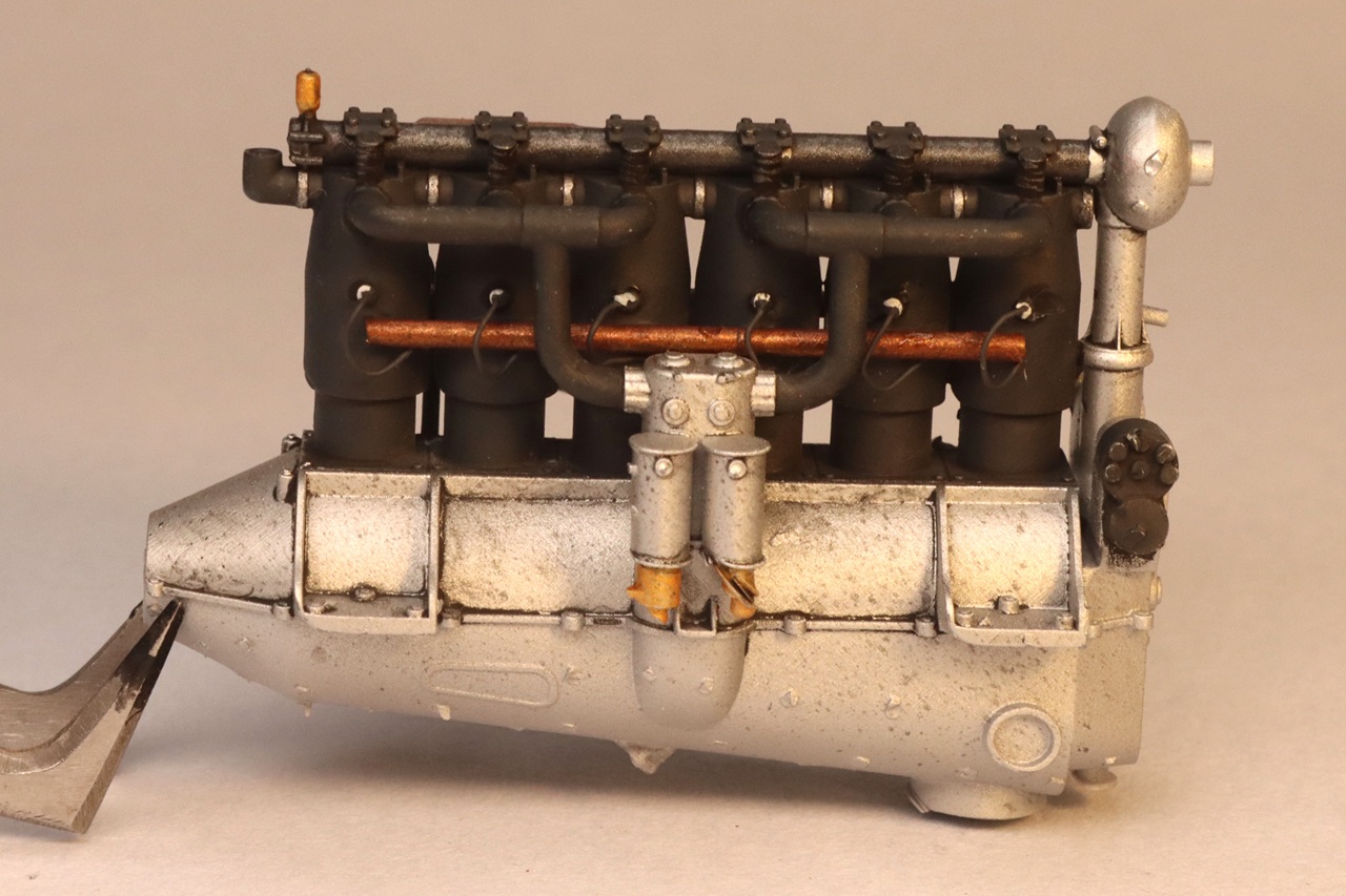
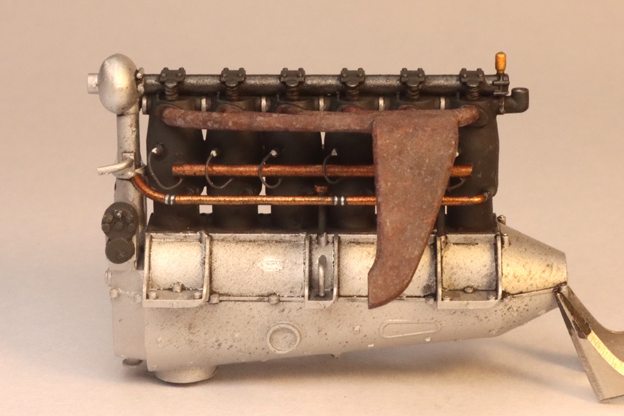
The 160 hp Mercedes motor is printed with its carburetors, intake manifold, coolant pipes, and ignition wire conduits in place. The details are nicely represented but it may have been better to print some of these parts separately as it is difficult to remove the print supports from between these delicate parts. The bottom of the carburetors had a printing defect in my kit. This doesn’t matter because only the top of the engine is visible in the finished model. I believe that the painting call-outs for the motor are reversed. The crankcase should be aluminum, and the cylinders are black. The engine access panels are printed separately and can be left off to display the top of the engine. The exhaust pipe has no opening in the end. I laminated some sheet styrene to the outboard end of the exhaust to increase its thickness so I could hollow it out. The propeller has very faint detail depicting metal tip-protectors. Be careful that you don’t sand off this detail as you clean up support nubs.
Fuselage
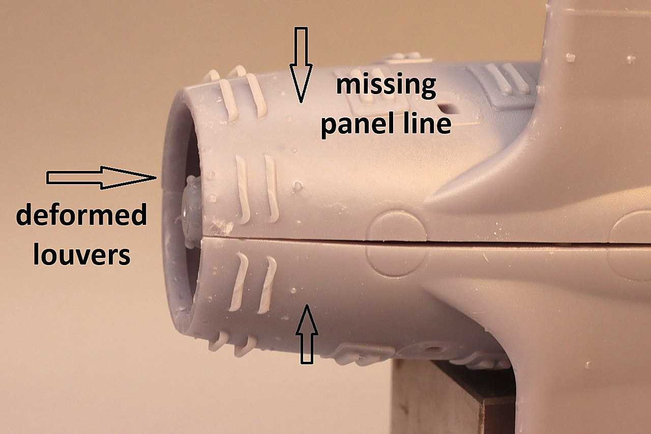
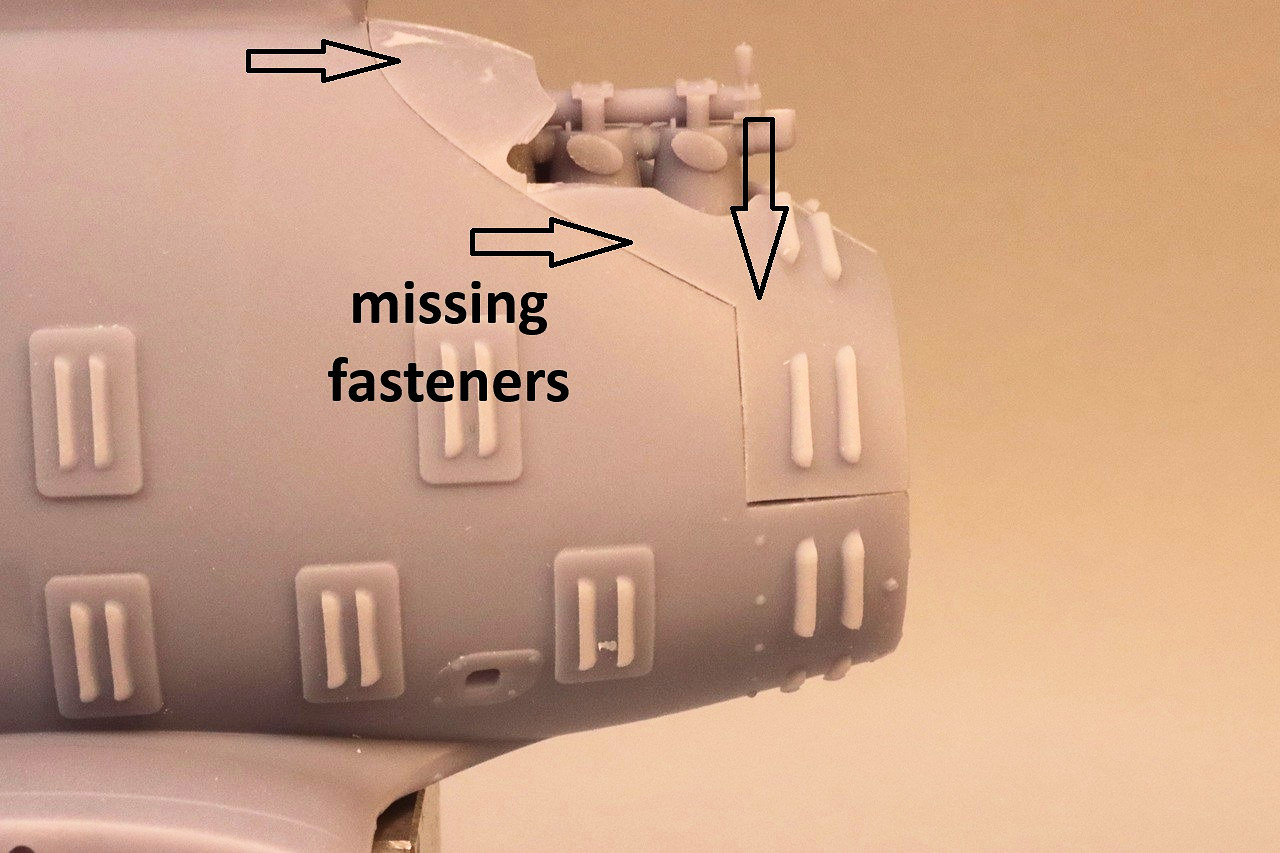
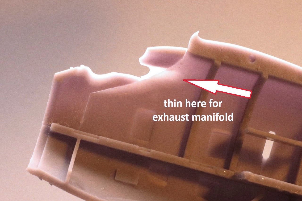
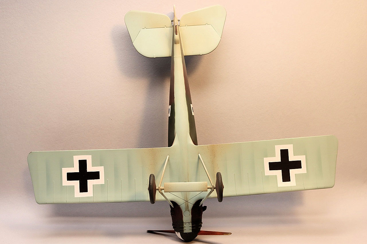
When installed, the engine access panels have a slight gap along the lower edge. I filled this gap with cyanoacrylate glue and scribed a new panel line. There is a missing panel line on the underside of the nose between the metal panels and the wooden fuselage. In photos of the real aircraft there are fasteners visible along the edges of the metal nose panels. This fastener detail is missing from the upper panels in the kit. I drilled holes through the panels and inserted short pieces of plastic rod to simulate the fasteners. I encountered some fit issues when closing the fuselage. The exhaust manifold of the engine needs more clearance for the engine to sit level. I thinned the inside of the starboard engine cowling to clear the exhaust. I found that the guns interfere with the back of the motor. Since the front of the guns is not visible after assembly, I chopped off about ¼inch from each gun. The seam on the bottom of the fuselage would close all the way and I had to use CA glue as a filler under the nose. The cooling louvers on the bottom of the nose did not print perfectly and look a little mangled.
Wings and Tail
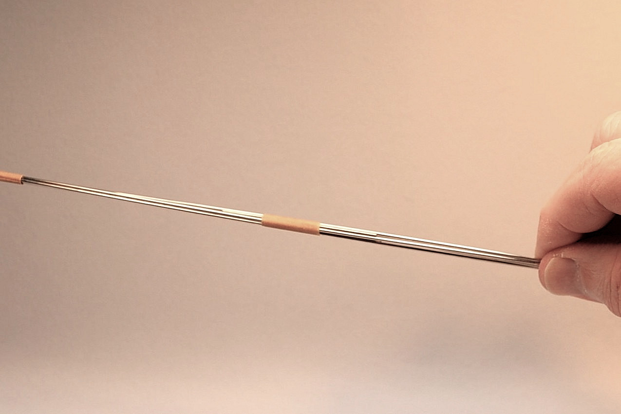
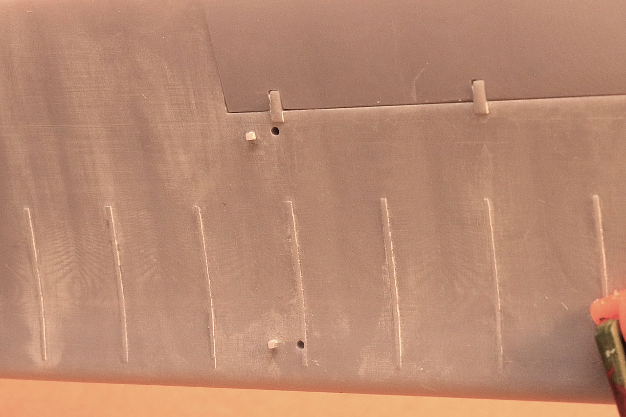
The upper wing is printed in three pieces, the lower wing is two pieces, and the lower wing roots are printed with the fuselage halves. The wing pieces and wing roots have spanwise holes to accept steel rods to ensure correct alignment and prevent distortion. The rods are not shown in the instructions and will need to be cut to the correct length. There is a slight sweep back to the wings so you may need to use left and right halves to the wires if they can’t be inserted past the middle. The upper surface of the wing has detail representing the bell cranks for the aileron control rods, but there is no corresponding detail on the underside of the wing and no locating holes for the actuating rods (parts #33). The trailing edges of the tail control surfaces have blunt edges and need to be sanded to a more streamlined shape. The tailplane braces (parts #32) and aileron actuating rods (parts #33) are almost as thin as print support attachments. It is a lot easier to replace these parts with plastic or metal rods than try to clean up such delicate parts. I had some trouble attaching the upper wing to the fuselage. The instrument (part#18) above the cockpit opening interferes with the rear of the wing and needs some trimming for good fit. On my build the upper wing had a greater incidence than the lower wing. Since the wing struts (parts #39) are all the same length my forward struts were too short. I sanded down the front of the wing mounting pylon by about 1mm until the struts all fit.
Rigging and Markings
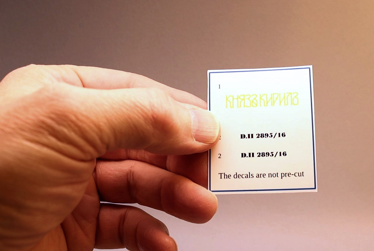
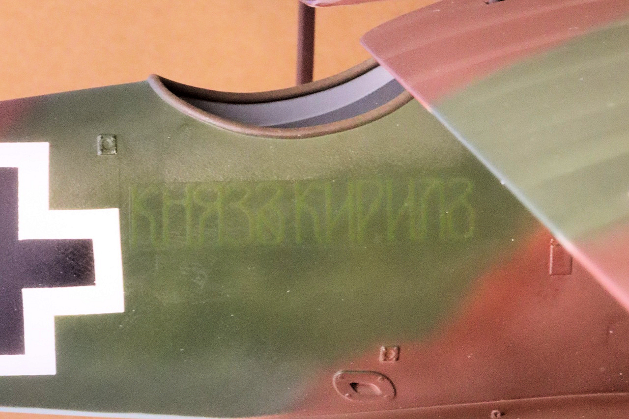
There are no rigging diagrams included in the instructions. I referred to Windsock Datafile #47 by P.M. Grosz to figure out the rigging locations. There are some small tabs printed in four places on the wings where rigging anchors would be. I cut these off and drilled holes to secure anchor points made from twisted wire. The national marking and larger personal markings are achieved using pre-cut vinyl self-adhesive masks. These masks worked very well. They adhered well without leaving any residue on the paint. Where the masks had to adhere over raised detail they tended to lift slightly. This was fixed by carefully slicing along the edge of the raised detail and applying clear varnish or tape over the cut. The marking option for Prince Kyril’s aircraft uses decals for the aircraft serial number and personal marking. These decals are printed with continuous carrier film and need to be trimmed close to the printed area. The cut edges of the carrier film tend to be visible through clear varnish. I needed to sand down the decals and re-varnish to hide the edges. The yellow ink of the personal marking is not opaque over dark paint and almost disappears after application. I used a fine tipped brush to trace over the marking with yellow paint. There are no decals provided for builder’s logos or data stencils. While these sorts of marking are common on WWI aircraft, I don’t know for a fact if they are appropriate for the marking options in the kit.
General Impressions
This is not an easy kit to build and will require some extra work from the modeler, but it does build into a good-looking and impressive model. I think that we are fortunate that MDesign is giving modelers the opportunity to build obscure and interesting aircraft that mainstream manufacturers have avoided. If this 1/32scale build seems daunting, be aware that MDesign also produces this same kit in 1/72nd and 1/48th. I am very grateful to MDesign and IPMS/USA for providing this kit for review.
Comments
a further reference for this kit....
The Bulgarian Hunters: Roland D.II & D.III in WWI
https://www.amazon.com/s?k=the+bulgarian+hunters&crid=3IQ407S5DYSF1&spr…
Higher resolution instructions available as a PDF
As I was recycling the box for this kit, I found a card with a QR code for downloading a high-resolution PDF of the instruction sheet. I could have downloaded the instruction and printed them at a larger size. oooops
Add new comment
This site is protected by reCAPTCHA and the Google Privacy Policy and Terms of Service apply.
Similar Reviews