
Fiat 806 Grand Prix, Part 2
This is a difficult kit to assemble with some significant fit issues with many of the parts. An old diecast version of this car was previously issued by Protar, and it looks like Italeri worked directly from the diecast kit. The Italeri plastic parts are identical to the Protar diecast parts, including ejection pins and sink marks. It looks like Italeri used the Protar parts to make their molds. This helps to explain some of the rough spots, lack of crisp decal on the parts, and all the nut & bolt fasteners.
Background
From Italeri’s website: The Fiat 806 Grand Prix adopted significant innovations for its time. The Fiat 806 was, in fact, the “progenitor” of the modern Formula One racing cars. Developed and produced by FIAT, the Italian automobile manufacturer in 1927, it could be considered the first Grand Prix car ever built. Thanks to its 180 HP 12 cylinder engine, the Fiat 806 was able to reach and even exceed the speed of 240 Km/h. However, the most important innovations were made in the development of the chassis, mechanics and bodywork. The engine and gearbox unit was, in fact, located between the two chassis bars in order to optimize the performance and the drivability.
The Kit
The initial chassis construction and engine assembly are covered in part 1 of the review.
Chassis Assembly Continued
Steps and 17 and 18 assemble and install the rear differential without problems. Step 19 prepares the wheels and tires for assembly. The brake drums, shown as part 135D, are actually two different parts, 135D, and 134D. They are very similar so I numbered them to keep them separate, but it didn’t seem to make much difference in the assembly. Decals are provided for the Pirelli labels on the tires, but Dunlop is molded on the sidewall. Instructions show to scrape the Dunlop off with sandpaper, and I installed that side to the inside.
Step 20 prepares the radiator core and shell for assembly. There is an option to paint the car number on the radiator or to use a decal. I sprayed the number using the supplied masks, but the number is barely visible if the grille is used.
The front axle is assembled in step 21 with a complicated series of assemblies for the suspension pieces. Keep track of the different configurations and where the rubber washers go to separate the different sides. Make sure to assemble the mounting bracket's parts 1B through 4B after the subassemblies E and F are installed on the axle.
The axle assembly is attached to the frame in step 23. I think that the rear mounting brackets parts 32B and 33B are reversed. Check the fit of the springs, subassembly H, to make sure the brackets are installed on the right side
Step 24 assembles the two halves of the fuel tank and some filling is required to patch the seams.
In step 25, spring sections are cut for the front and rear brake cables. The cable call outs are mixed up as the longer spring section, C, should be attached to the front brake drum, not spring section D as shown on the instructions. The shorter spring assembly, which is also labeled C, should be attached to the rear brake levers.
The gas tank, brake cables, brake drums, front steering tire rod, and lower engine hood are all installed in step 26. The brake lever, 29B, meshes with the brake lever 141D, although the teeth didn't mesh very well and weren’t strong enough to pull the cables. The instructions show the brake disks being attached loose to the axles, but I used glue to hold them in place.
The wheels and tires are installed in steps 27 and 28 but I decided to hold off until the kit is more complete. Step 28 also shows installation of the instrument panel and gauges. The instructions show photoetch pieces for the gauges, with the decals applied on top of the photoetch. The decals for the gauges are quite thin and I crumpled one of them trying to get it in place.
Engine Installation
Step 29 installs the engine into the chassis. Or at least it tries to. Several problems popped up when trying to insert the engine.
The opening of the floor is not wide enough for the wheel on the transmission, requiring cutting back the photoetch floor surface and the plastic underneath. Parts 114D and 113D that were installed to the front of the engine in step 8 interfere with the chassis. I tried cutting off part 114D but that wasn't enough so I left off the entire 113D and114D assembly and replaced it after the engine was installed.
The biggest problem however is that the holes in the chassis for the engine mounts have a different spacing than the holes on the engine block. The rear holes appear to be in the right location as of the steering arm fits into the notch on the frame. I ended up using the rear screws and not installing any on the front mount.
Both part 1K and hose D in step 29 are shown too short, so check the fit before cutting.
After installing the engine I fabricated brass tubes to organize the ignition cabling and installed smaller wires to replace the kit’s over-scaled cables.
Body Installation
Step 30 shows installation of springs on the hood latches parts 37E through 39E. The clear part for the windscreen, part 2CF, is about 3/16 inch short of the frame. I cut out a piece of clear acetate and used that. The tabs for the heat shield for the tailpipe, part 2PE, are too far apart to fit the holes in the body. New holes needed to be drilled for anchoring the heat shield. I used the photoetch brass without painting as it fit my steampunk theme.
The steering linkage assembly H is installed in step 32. My steering box froze up by this step, and I think it really would be difficult to actually get the steering to work without breaking the plastic pieces.
I counted all the rivets on the body and found there weren’t enough, so I added a few dozen Archer resin rivets for my steampunk vehicle. The body was painted with Alcad and AK Interactive copper metal finish paints. The rivets were highlighted with AK Interactive brass. The body was installed to the chassis at this point and fit pretty well. I did have to loosen the rear suspension to move it out of the way to get the back screws installed for the body. The rubber driver seat is also installed by pushing the pins into the back of the cockpit.
The last step installs the exhaust headers, hood, and the spring latches to hold the hood down. The left exhaust header required some coaxing to get it to align with the exhaust pipe, which resulted in the header being too high. The hood on the left side needed to be cut down to fit over the exhaust pipe. The photoetch brass straps for the connection between the exhaust header and the exhaust pipe are too small to fit over the plastic pieces. Both the header and exhaust pipe needed to be trimmed down to get the brass pieces to fit.
The springs and latches for the hood were very difficult to install, and did not work very well. The instructions show to hook the bottom of the springs on a tab on the chassis, which I didn't think would hold the spring in place. I drilled holes in the tabs, slipped the end of the spring in, and secured it with a drop of superglue. Once installed the latches didn't work as they slipped out of the holes on the hood. One of the pins broke off the latch and I replaced it with brass rod, which allowed bending the angle to pull tighter. The two sections of the hood fit over a pin on the body, which remarkably I had not broken off yet, and over a pin through the front radiator cap. The holes on the hoods need to be drilled out but it worked pretty well. The hood fit fairly well.
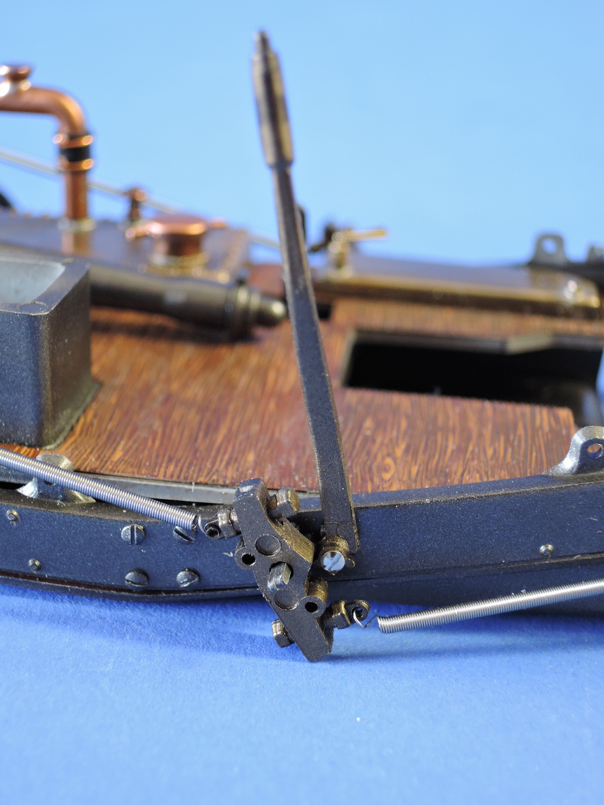
The starter handle is also installed and required a severe bend upward to get it to connect to the engine.
Wheels
I had delayed installing the wheels until everything was finished. The thin axles weren't up to the task, and I broke one off and stripped the threads on two others installing the wheels. This left the wheels kind of loose and difficult to line up, which probably would've been a problem even if I hadn't stripped the plastic threads.
Summary
In spite of all the fit issues the kit ends up with an impressive looking model. The body fits pretty well and lends itself to some nice finishing options like the steampunk version I used. The steering and brake lever are supposed to work but the plastic stripped or broke on my kit. This may be a result of the diecast heritage of the kit, but the plastic just wasn't up to the task and not strong enough. The fit issues with the engine should've been resolved, particularly in a kit that cost this much. I had sufficient bolts nuts and tubing pieces to complete the model with some spares left over.
I enjoyed building the kit despite the issues, but only recommend this kit to experienced builders who are ready for the challenge of reworking parts to get everything to fit.
Thanks to Hobbico for supplying the review sample, and to Italeri for making this interesting kit.


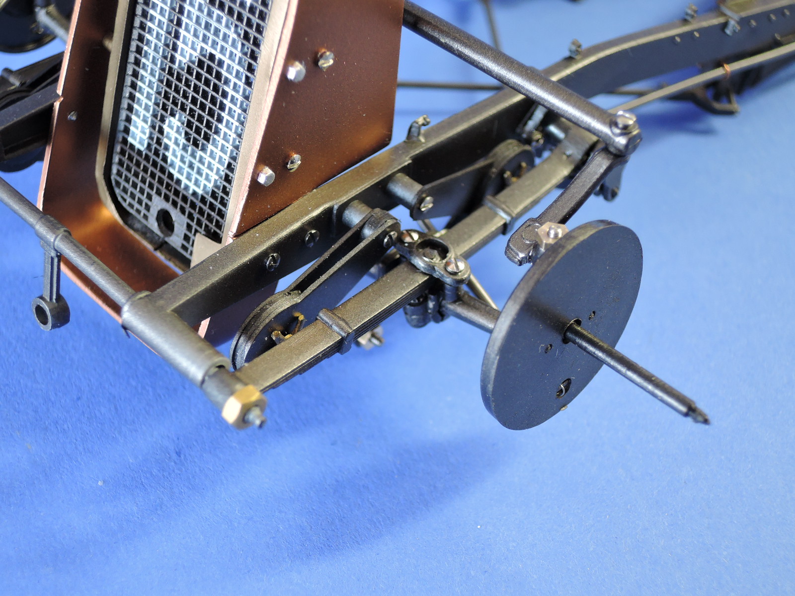
Rear suspension
Front suspension includes a complicated series of assemblies
Brake lever - teeth don't mesh well and aren’t strong enough to pull the cables

Very thin decals applied on top of the photoetch

Engine - opening of the floor is not wide enough for the wheel on the transmission
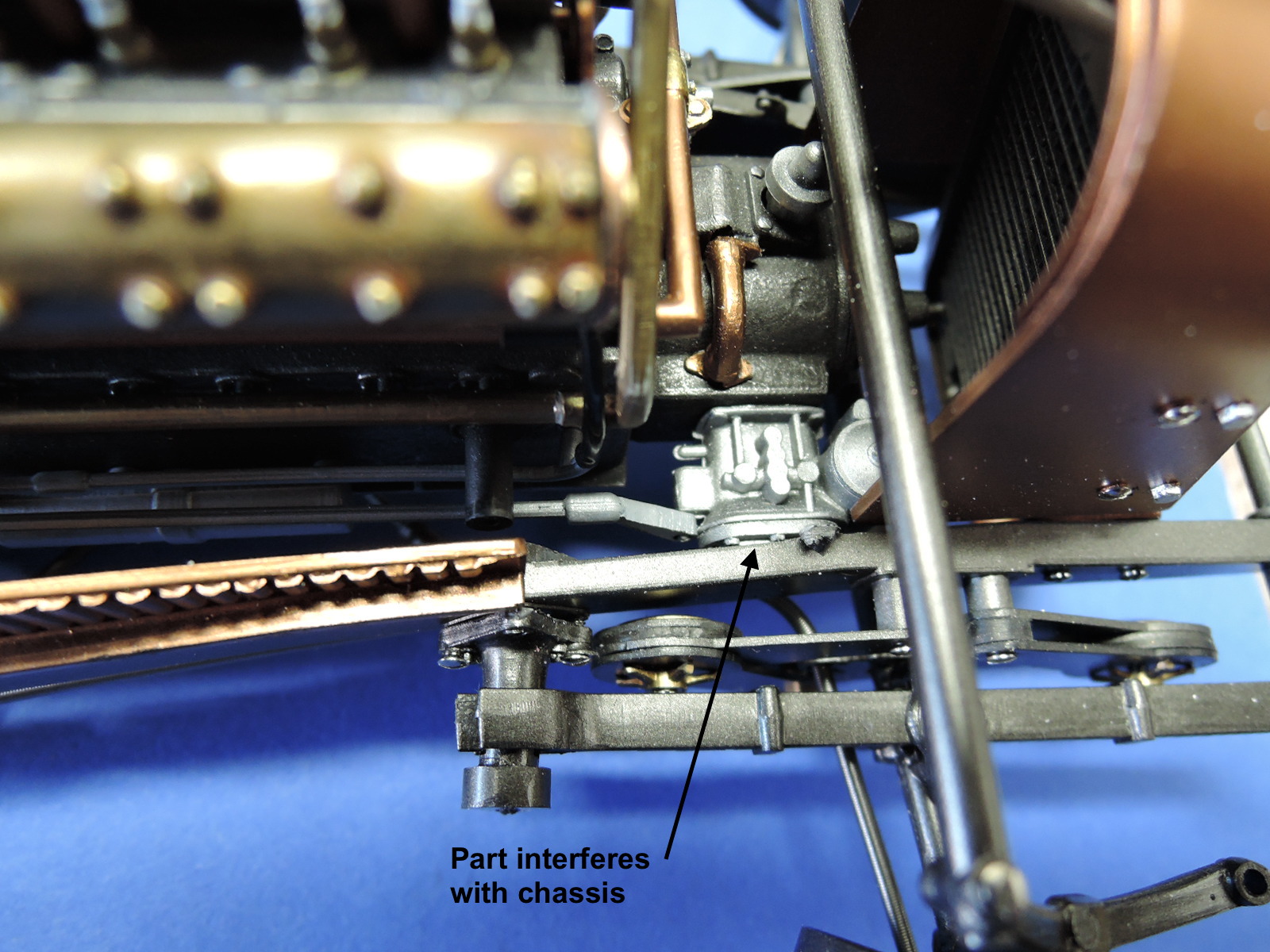
Engine - Parts 114D and 113D interfere with chasis
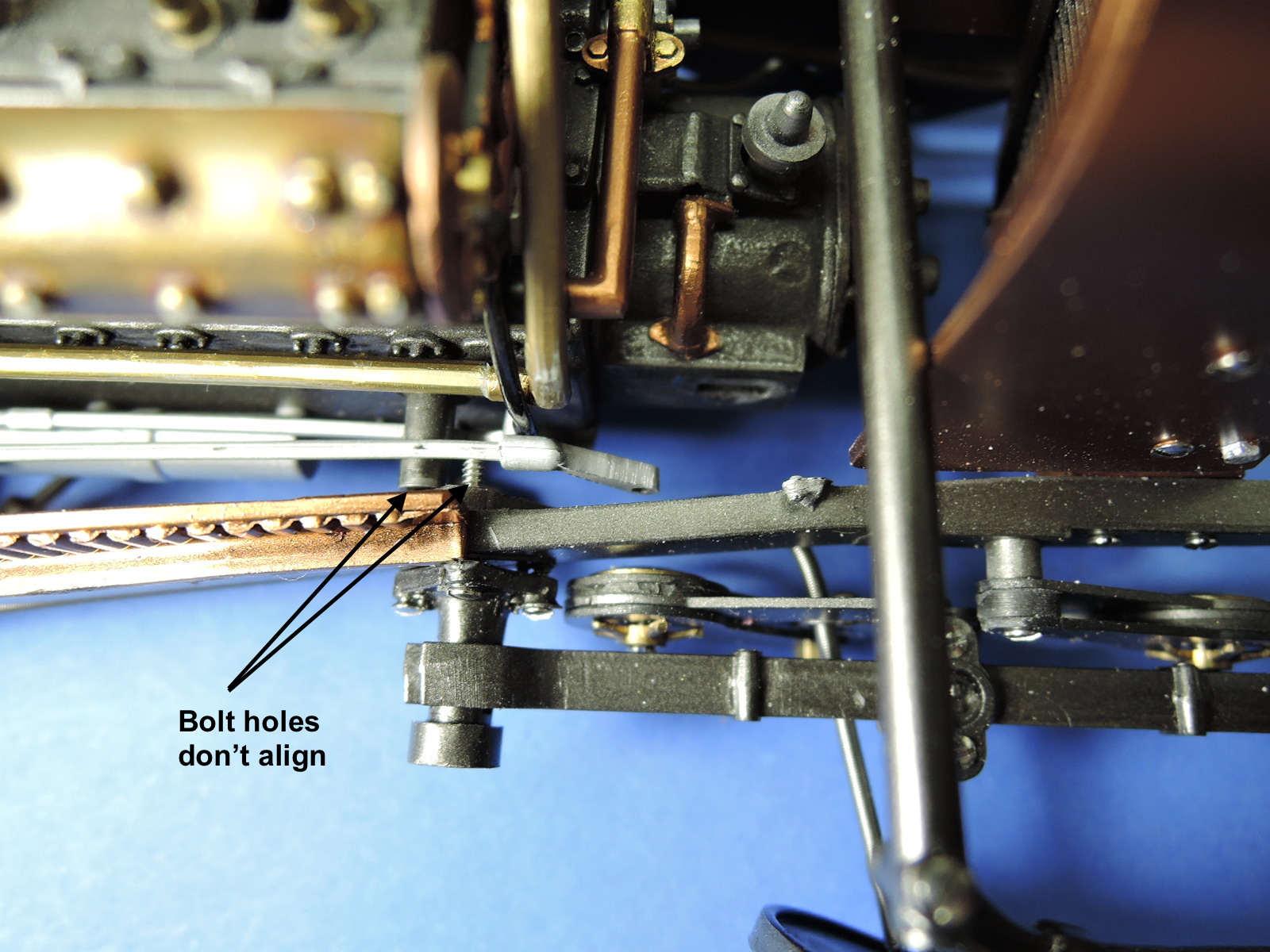
Engine - the holes in the chassis for the engine mounts have a different spacing than the holes on the engine block
Engine installed
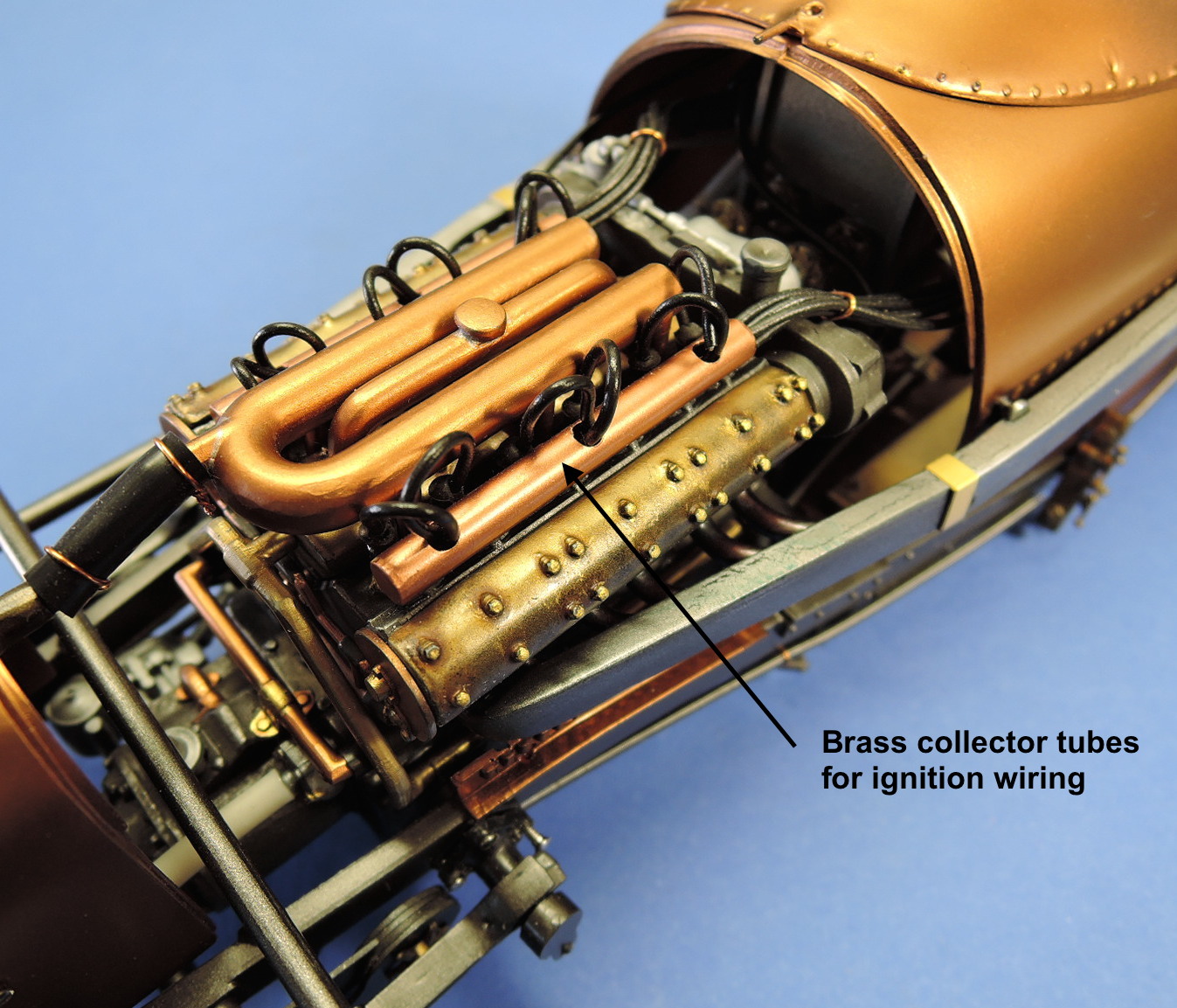
After engine was installed, brass tubes were fabricated to organize the ignition cabling
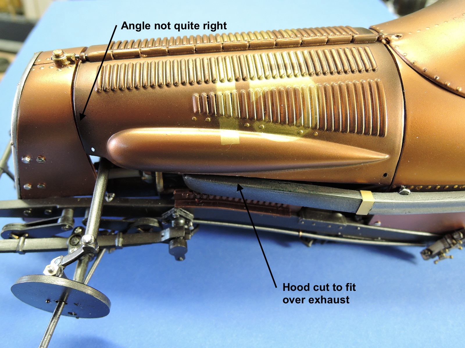
The left side of hood needed to be cut down to fit over the exhaust pipe
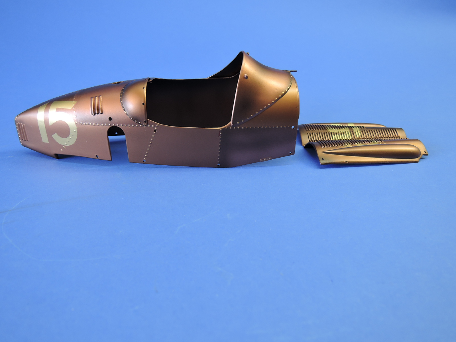
Body painted with Alcad and AK Interactive copper metal finish paints

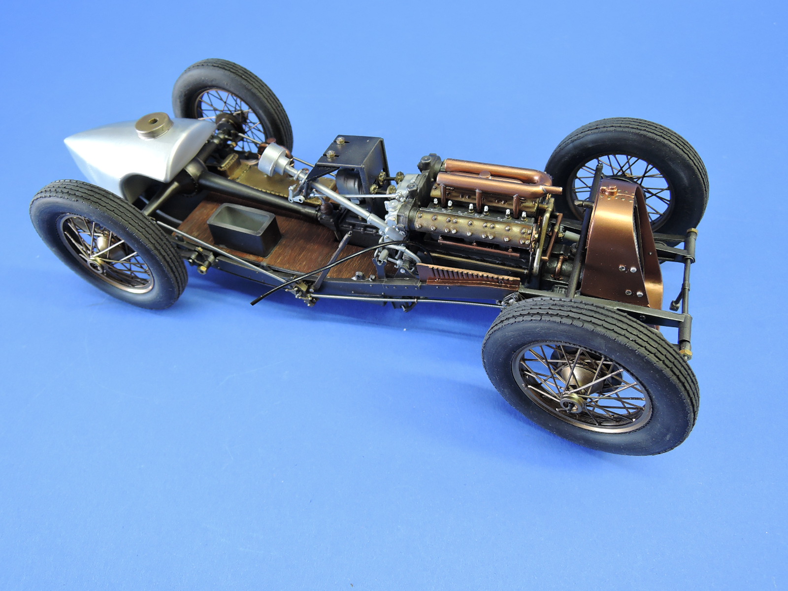
Completed kit, above engine

Completed kit, left

Comments
Comment regarding misfits
Hi William. I just finished this same model and I did NOT experience all the fit problems you mentioned in this article. I then look for the reasons. I don't know if anyone told you... many of your fit problems result in your engine mounted to the wrong screw. On your photo 7 of 14, you clearly show the misaligned front engine mount. That is because you are trying to attach the engine to the center (and higher) screw on the leaf spring bracket instead of to the rear screw of the leaf spring bracket. This no doubt has caused the engine to be higher than intended, that's probably why your carburetor is hitting the frame, and that disc on the side of the transmission is hitting the floor. See posted photo here: https://vgy.me/delete/W1rRqQzMiWgA
I built the original metal version, I thought it was one of the more enjoyable builds I did.
Paul
Misfits
Thanks for the post and the heads-up. ALL of which I experienced too - and more.
Nonetheless, still a great-looking model in the end but definitely not for novices.
I cannot see how Paul can compare this build to the metal one, They are two different kits.
Richard
Add new comment
This site is protected by reCAPTCHA and the Google Privacy Policy and Terms of Service apply.
Similar Reviews