
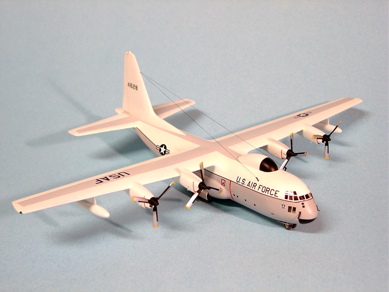
JC-130A Hercules
When the package arrived I was expecting a C-130A and was surprised to find in its place a model kit for the JC-130A. I didn’t have a clue on what the “J” stood for, so off to the internet to find out. Well, they were built to track and retrieve missiles tested over the Atlantic test range. Further snooping found that eight C-130A’s were built as JC-130A’s and later several B models were built as JC-130B’s and were used to track and retrieve space capsules (i.e. film capsules from spy satellites) on the Pacific test range.
Upon opening the box one will find 85 parts made with a soft gray or clear plastic. The instruction sheet consists of 5 pages; the first page gives a short history on the Hercules but no mention of the JC-130A. Also all the paints are listed with Humbrol numbers. The second page is a drawing showing all the parts on the sprues. Note that the sprues themselves do not have any part numbers on them, but it’s easy to figure out the part using this drawing. The next two pages deal with the assembly of the parts and the final page is the three - view drawing with color and decal locations called forth. The decals are flat coated and are moderately thick, but react to Micro-Sol to conform to the painted model surface. Four national insignias are provided, all the same size. This will be alright for the wing location, but this size is too large for the fuselage location. You will need a 20” national insignia for the fuselage.
Being an Eastern Europe limited run kit the parts do not have any pin/hole location connectors for you. You’ll have to sand the edges and check the alignment as you glue the parts together. In addition, there are no internal marks or slots to locate where the internal bulkhead or cargo floor goes. Use the instructions as a guide for placement. The main landing gear bays have to be trimmed and fitted to the fuselage to get a tight fit. Once the main fuselage is together you will have to attach the horizontals/beaver tail assembly to the rear of the fuselage with a butt joint. Since I was keeping the ramps closed up I reinforced this area with a strip of plastic. On top of this is attached the vertical tail. You will have to be careful to get all these parts aligned right or it will affect the look of the model. All the spinners on my kit had deep sink marks on them, these were the only sink marks on the kit, but these will be hard to take care off. The wheels (main & nose) had no holes on the back side to mate with the landing gear. You will have to drill out these holes yourself; I used a #55 drill on the main wheels and a #67 drill on the nose wheels. In addition, all the landing gear doors are too thick and need to be thinned using files and sandpaper.
This kit has recessed panel lines that vary in thickness or depth. Also some lines continue slightly beyond the stopping areas and this is apparent. This is Amodels second issue of the C-130A and there are dents in the molds that show up as positive bumps on the fuselage surface.
These have to be sanded down to correct this issue. Because of this and the problems with the recessed panel lines I decided to sand all the lines down till they were gone and rescribed the control surfaces and the doors.
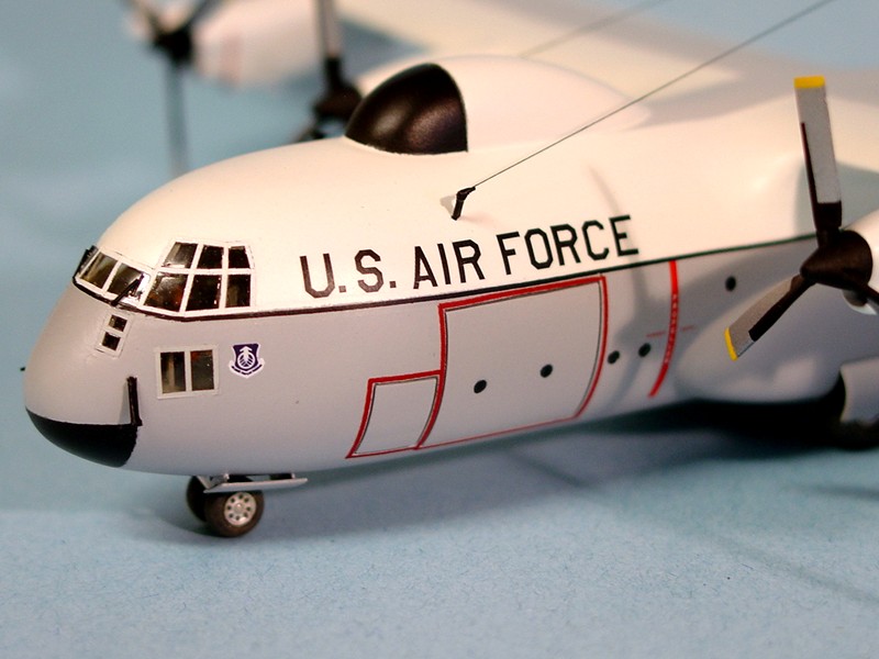
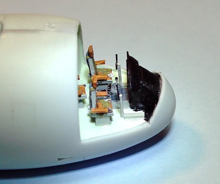
There is no cockpit provided in this kit, which is not a problem if you paint the inside of the cockpit clear plastic with black paint.
Then load up the nose with weight to balance out the model. Before you prime make sure that you mask off the windows so paint will not cover them. Personally, I used plastic sheet to make a cockpit floor, internal equipment, seats, instrument panel, throttle quadrant, etc…and still found space for a lot of lead weight.
The dome that sits on top of the JC-130’s is about 1/8” (.125”) too long. I took a razor saw and made a cut at an angle whose pivot point was the front tip and angled up facing aft. The cut was such that it removed the 1/8” at the rear. The edges were sanded smooth and the old line marking the forward portion of the dome was filled as it angled back now do to the cut. A new line was marked and scribed. Well that describes some of the issues that will await you when you start this kit; I hope that I have identified them for you so you know them in advance.
The model was given two coats of 1200 Mr. Surfacer primer, sanding between the coats to find and fill and surface blemishes. The model then sprayed with white lacquer paint and allowed to dry 24 hours. It was then masked and the grey undersides were painted again with lacquer paint. Once this too had 24 hours to dry the upper walk areas were painted with light grey lacquer paint and allowed to dry. The decals were then applied and the model was finished.
To make an accurate C-130A model:
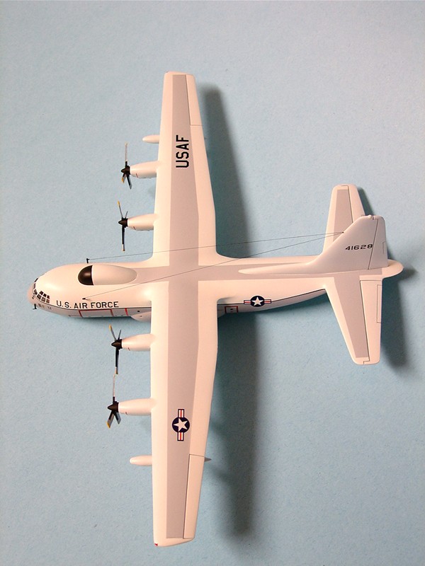
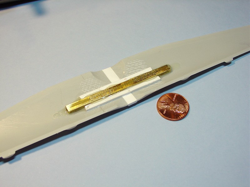
- C-130 wing span is 132 feet, 7 inches which in 1/144 scale equals 11.05”. The Amodel kit wing span measures 10.81” and is short by .239”, close to ¼ inch. I took a piece of .250” x .080” Evergreen plastic stock and sanded the size to .239” then cut the wing in half and glued in this spacer.
After it had harden I reinforced the underside with some plastic square stock and brass channel that ran 90 degrees to the cut or parallel to the wing span. After that cured the wing halves were glued together and the upper surface was filed and sanded to shape. Later when the wing was fitted to the fuselage there was a gap on each side on the bottom of the wing. This gap was filled with Apoxie-Sculp epoxy putty.
- The fuselage length needed a little adjustment. I added 1/16” (.060”) to the aft beaver tail and that problem was solved.
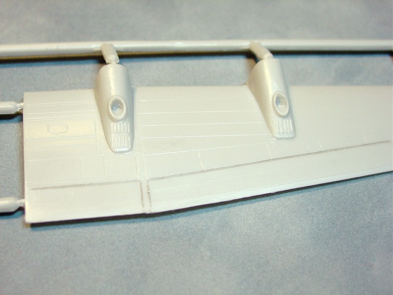
- The engine nacelles on the C-130A are extended on the undersides of the wing more than the later versions. Amodel nacelles are correct for the B-H models but are short for the “A” model. This was corrected by using Apoxie-Sculp to extend the nacelles, after hardening the epoxy was sanded to shape.
- The engine nacelles forward of the wings L.E. are not the correct length. The C-130A used the T-56-A-9 engines. The B-H models used the T-56-A-7 or 15 engines which were longer than the -9 engines used on the “A” model. The kit nacelles are in between these two in length, too long for the “A”, but too short for the B-H models. In 1/144 scale I had to shorten the kit nacelles by .040” to get the correct length.
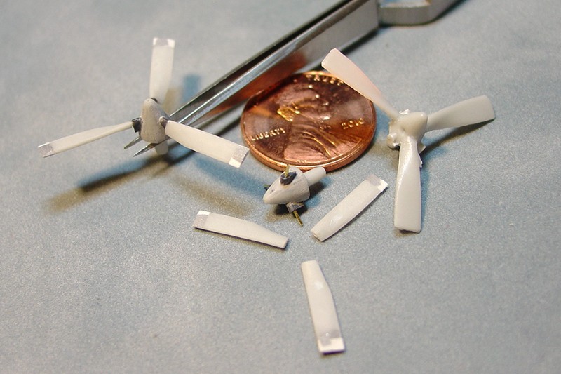
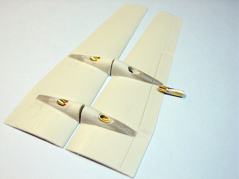
- Amodel has provided the 3-bladed props that the C-130A’s had, but got the diameter wrong. The diameter should be 15 feet, but measures out to 13.5 feet, which is what the 4-bladed props diameters were. One has to add about 1/16” (.060) to the ends of each propeller blade to correct this error.
- I also decided to correct the pitch of the props at the same time; no photos I found on any C-130 had the props pitch set like the Amodel had them molded. So I cut them off, which allowed me to fill the sink marks on the spinners then reattach a stub on the props, drill and place a pin in each stub and then attach the lengthened blades to the stubs via the pins. The pins allowed me to set the pitch I wanted.
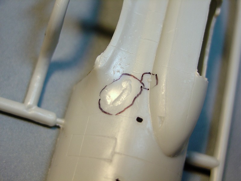
Amodel has four windows on the left/right forward fuselage, this arrangement is correct for the B-H models but not for the C-130A’s. Just above the third window back from the front, there is a window above high on the fuselage, plug this. Then drill a new window 1/8” (.125”) further aft than the third window, fill with a clear plug provided and you have the correct pattern for the “A” model.
- Some sources say the first 16 C-130A’s had a left fuselage cargo door, another source said all “A” models had them. Doesn’t matter, if you use the serial number provided that’s the fifteenth model so a new cargo door needs to be scribed on the left side and outlined in red. Check photos for location, but roughly it butts against the crew access hatch on the left and runs almost to the third window on the right, height wise it’s about 6 feet high.
- Again sources differ on the number, but with using the kit serial number this plane had a two piece nose gear door. Later A’s and all C-130’s had a one piece door that opened aft of the bay. The two piece door ran up the side of the fuselage. You’ll have to take the kit nose door, thin it down and cut it in half. Then glue some supports on the undersides and glue the doors to the fuselage next to the doors. A good drawing of this can be found on page 7 of the Squadron/Signal book “Walk Around C-130 Hercules”.
- I soldered thin brass strips (.010” x .018”) to .010” brass rods to create the two pitot tubes up front and the two antennas that mount on the upper forward fuselage. A hole was drilled in the vertical tail L.E. about ½” down and two pieces of .006” fly fishing thread were glued into this hole. Each thread was then placed around one of the antennas and glued in place.
I can recommend this kit to anyone who has had experience with Eastern European limited run model kits. This is a kit that will require a certain amount of care to assembly, watching out for the alignment of parts, the fits of parts and the finishing of the model. An acceptable representation of a JC-130A can be made. I want to thank IPMS/USA and Amodel for the opportunity to review this product.
Thanks to Amodel, Hobby Terra and IPMS/USA for this opportunity to do this review.

Comments
Add new comment
This site is protected by reCAPTCHA and the Google Privacy Policy and Terms of Service apply.
Similar Reviews