
Flakpanzer Gepard
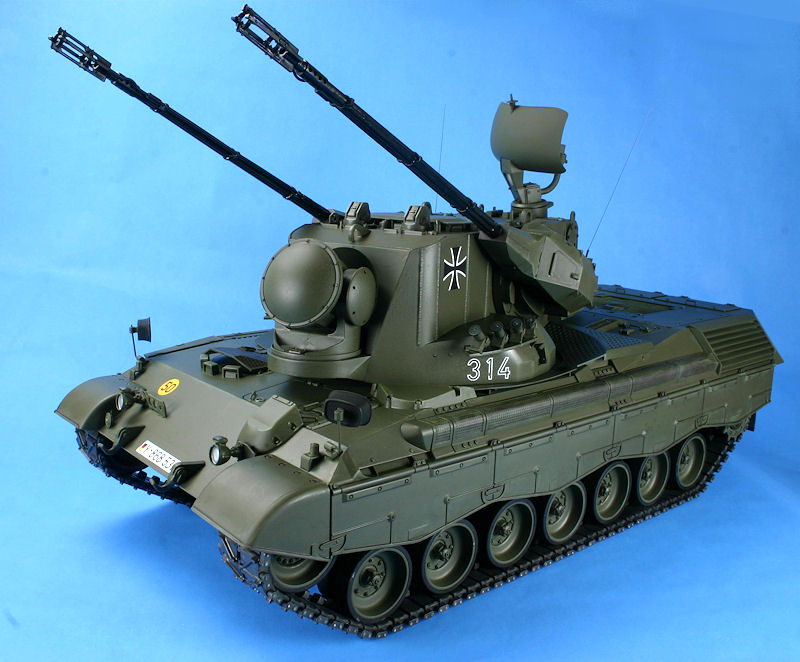
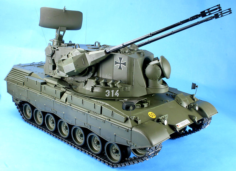
The Flakpanzer Gepard was a German design that began after WWII in 1955. The design and prototype stages took a very long time and the first Gepard was not deployed till 1975. The basic design had two 35mm Oerlikon cannons mounted on the outside of a turret that has two radar tracking systems. The first radar was 360 degree surveillance radar that tracked and identified targets. Once identified, the target was transferred to the tracking radar that controlled the two guns. This system allowed the two radars to work independently of each other, with the tracking radar concentrating on the target while the surveillance radar looked for other targets. The chassis was based on the Leopard MBT. The Gepard was removed from service in 2010 when it was replaced with the SysFla mobile and stationary air defense system.
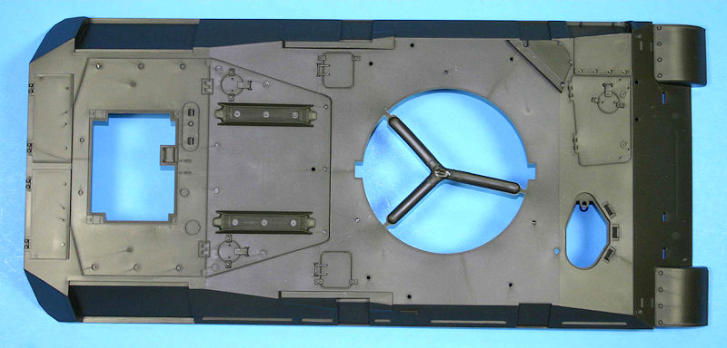
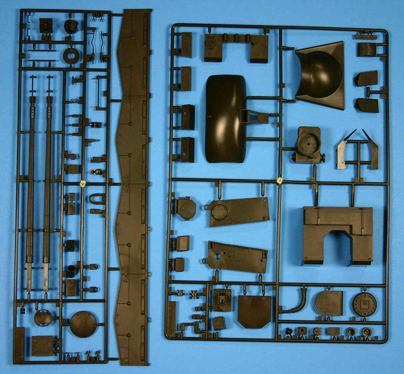
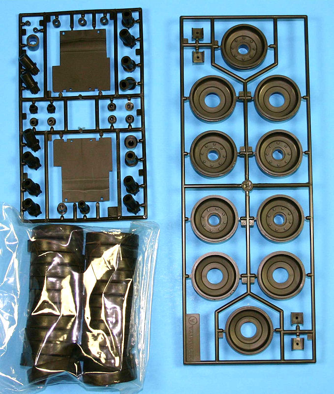
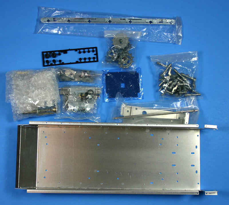
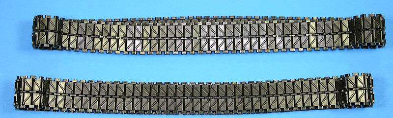
The kit is a former radio controlled model that has all the RC equipment removed to depict a static model. There are plastic parts, metal running gear, rubber tires, a pressed metal hull, preassembled tracks, and a bushel of screws, washers and nuts.
Steps
- This step begins with the assembly of the lower hull and is all metal parts that are screwed or bolted together. I used a 20 compartment plastic tray to separate the bolts and nuts. In the instructions, these parts are called out by number and size. Rather than measure each time, I placed the parts in one of the compartments (the part numbers matched the bin number) which allowed for easy identification and retrieval. The first parts assembled here are the torsion bar stays and the track tension adjuster. The second half involves the attachment of the suspension housing, then the suspension arm attached to the torsion bar. This allows the suspension arms to articulate just like the real tank and to look realistic when placed on a diorama other than a flat surface.
- This step attaches the lower hull parts like the return roller and suspension arm stops. This is very straightforward without any difficulties.
- This step attaches the shock absorbers and the gear box. The shock absorbers are moveable, but are for show only, as there are no springs inside. The gearbox is a leftover from the RC kit that is used to mount the drive sprocket in step 9. After the gearbox is installed, you may want to go back to the slot the gearbox is lowered into and fill in the slot with plastic sheet. This slot is very noticeable and should not be there in a static model.
- These steps build the two idler wheels and the 14 road wheels. I left the rubber tires off to paint and weather these items, then add the tires just before mounting them to the model.
- Repeat of Step 4.
- This step mounts the road wheels and idler wheels. I did not do this step in order, which allowed me to paint the chassis and weather it before I add the road wheels.
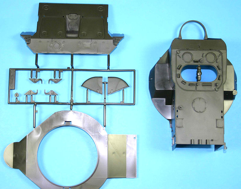
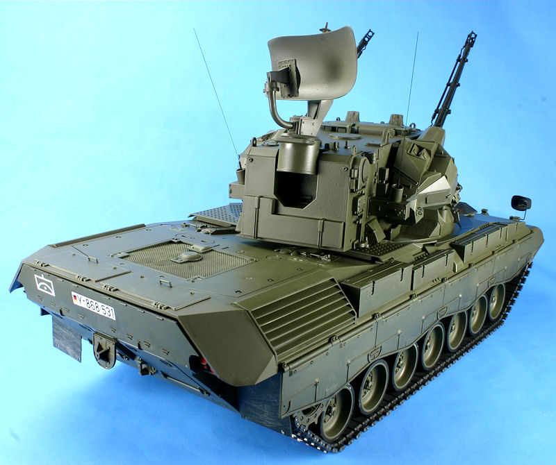
- This step builds the rear panel of the lower hull. The plastic parts are added, along with a rubber mud flap. Since the mud flap is actually just hanging there, I delayed adding to the model so as to keep from damaging it during painting and handling. Just remember this is a rather large model and is heavier than most of us are use to; therefore, more caution is required when handling.
- This step bolts on the rear stay to mount the upper hull to the lower hull. It also includes the mating of the rear panel to the lower hull. This is where I encountered my first real fit problem. There four bolts used to hold the rear panel to the metal hull. The two bottom bolts fit the holes and the rear panel locating arms. The two upper locating arms just did not fit. It took a lot of filing and sanding to get a usable fit that would actually hold the part in place. This step also adds the return rollers.
- This step adds the preassembled tracks and the drive sprocket to the model. I delayed this step till the very end when all other handling was complete.
- This step begins the assembly of the upper hull with the addition of the headlights, hatches, and the front stay. This stay holds the front upper hull to the lower hull. Since this is a static model and will not require removal of the upper hull to service the RC parts on the inside, I built the stay as depicted with two bolts showing on the front glacis of the tank. After I had finished steps 10 thru 13 and I wanted to permanently mount the upper hull to the lower hull, I then disassembled the stay and put epoxy glue on the stay and the upper hull. I then bolted the parts in place and let the epoxy glue dry for two days. When the glue was dry, I backed the bolts out and filled the two holes in the glacis with plastic and filler, then sanded it to match the rest of the model. At this time the two bolts that hold the rear of the upper hull to the lower hull were also handled in the same manner. After this is complete, no bolts appear anywhere on the upper hull. I did not add the two sets of headlights at this time, again to keep from breaking them off during handling.
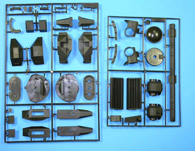
- This step builds the side equipment storage boxes, the air intake cover, and assembles the two rear view mirrors.
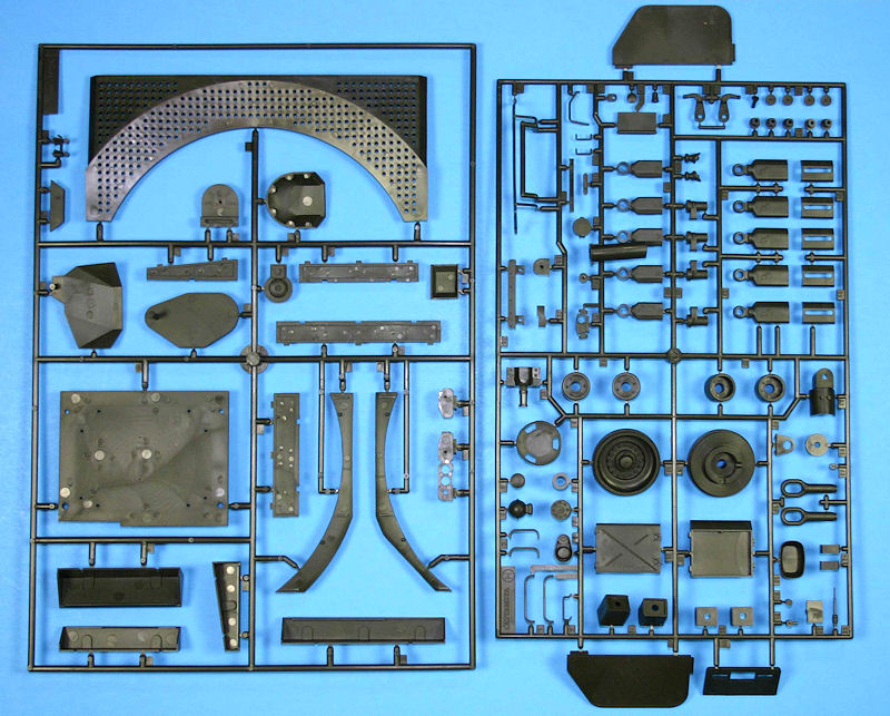
- This step adds the screens to the left side of the vehicle and other sundry parts. The part P4 is a screen that fits on the rear of the hull and the turret passes over it with very little clearance. This part did not want to fit and since you can see thru it, I waited till much later in the build to add it. After the base hull color was applied, I then filed and sanded until this part fit and allowed the turret to fit and rotate without interfering with this screen.
- This step adds the rear deck, rear deck handles, and the right side storage boxes (see step 11). This step also adds the two rear view mirrors and since they stick out quite prominently, I left them off the model until the end. I used bare metal foil to depict the mirrors.
- This step begins the build of the turret with the assembly of the surveillance radar. The build is straightforward and the parts fit together well. If you follow the instructions, the antenna will rotate.
- This step builds the surveillance radar base. If you follow the steps, the antenna will till up and down. This will facilitate your setting the model in your diorama with the antenna at the desired angle.
- This step builds the smoke dischargers and the upper turret hatch. The underside of the hatch is detailed and there are painting instructions. However, unless you build an interior, there is no reason to show the turret open. There is a fit problem with the smoke dischargers. You can assemble the individual smoke cans, but do not mount them to the holding rack. Wait till you have attached the holding rack to the turret in step 21. There you will have to adjust where the smoke dischargers sit on the holding rack so they can clear the turret.
- This step adds the turret base to the turret and fills in the front radar area. The upper hatch is attached along with various small parts to the top and left side.
- This step adds additional items to the top of the turret and parts to the right side of the turret. This step also adds the tracking radar base to the turret. If this is done correctly, the tracking radar will pivot.
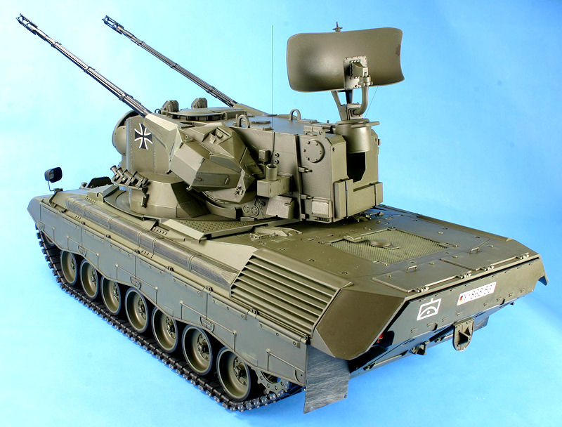
- This step mounts the surveillance radar to the rear of the turret. There were fit problems here and it took quite a bit of effort to get it even close to a good fit.
- This step builds the tracking radar. It goes together well and, if done correctly, the radar will tilt up and down.
- This step adds the additional items to the top of the turret, mounts the tracking radar to the front, and adds the smoke dischargers. Here you need to mount the holding rack first, and then mount the individual smoke dischargers. (See step 16) The last item here is the o-rings that allow the cannons to tilt up and down. These are a press fit without glue.
- This step builds the cannons. You will need to glue them together and let them dry before attempting to remove any seams.
- This step adds the cannons to the cannon housings. Make sure you do one side at a time, as you can get the parts mixed up if you are not careful. These are subassemblies that will add additional items in the next step.
- This step finishes the cannon housings and adds the mounting flange. There is a poly cap on the inside of the mounting flange that will be the mating part with the connecting rod. The additional parts to the cannon housing and the sensing cords finish off the two cannons.
- This step attaches the two cannons to the turret with a connecting rod. This connecting rod has a hex profile on each end. This hex profile will mate with the hex profile on the mounting flange. Make sure that the two cannons are parallel, that is the connecting rod is inserted into the hex holes correctly. This is done without glue as a press fit. This will allow the cannons to tilt up and down.
- This step adds the side shields and inserts the turret into the upper hull mounting hole. The turret is free to turn, allowing you to display the model as you desire. At this time I added all the road wheels, the tracks and, finally, the little parts that I left off to keep from breaking.
Painting and Decals
There are only Tamiya referenced colors. The paint scheme for the Gepard during the 1970’s was overall Olive Drab. In the mid 1980’s the NATO three-tone Green, Brown and Black camouflage was used. The cannons were a semi gloss black, but I can’t imagine them staying in a semi gloss for long due to weathering and just plain dust and dirt. The decals were minimal and were applied over a flat area without any problems.
Conclusion
As stated before, this is a stripped down RC model to build a static kit. The model generally goes together well, but my big concern is the attachment of the upper hull to the lower hull. If you follow the instructions you will have 4 large bolt heads sticking out of the upper hull in very visible locations. Given the price of the kit, I would have expected a few “new” sprues to allow for the mating of the upper and lower hulls without showing the four bolt heads. There could have been a few extra pieces to fill up the gearbox slot. Other than those concerns, this will make an impressive model,especially the long 35mm cannons. I can recommend this kit to those who want a something a little different in the modern armor category, and who also have a lot of shelf space and deep pockets.
References
Most of the references I could find are in non English languages. I did find some online sites that show a YouTube video of the Gepard in action and have general information.

Comments
Add new comment
This site is protected by reCAPTCHA and the Google Privacy Policy and Terms of Service apply.
Similar Reviews