
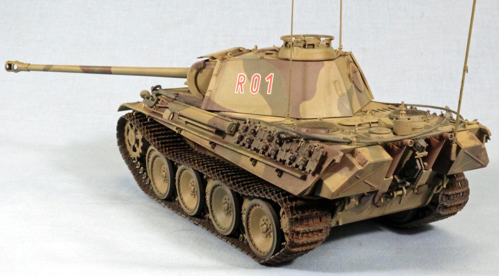
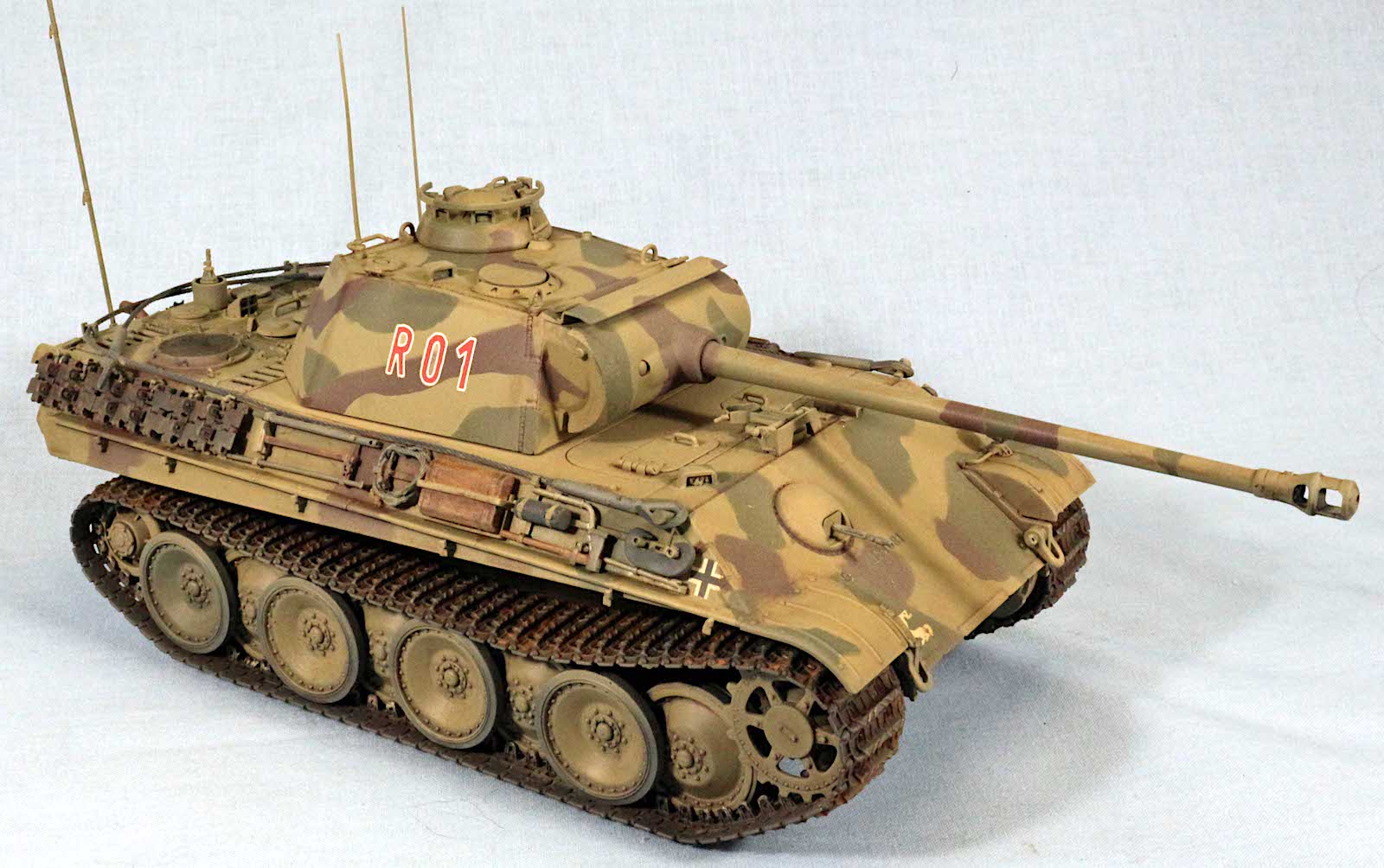
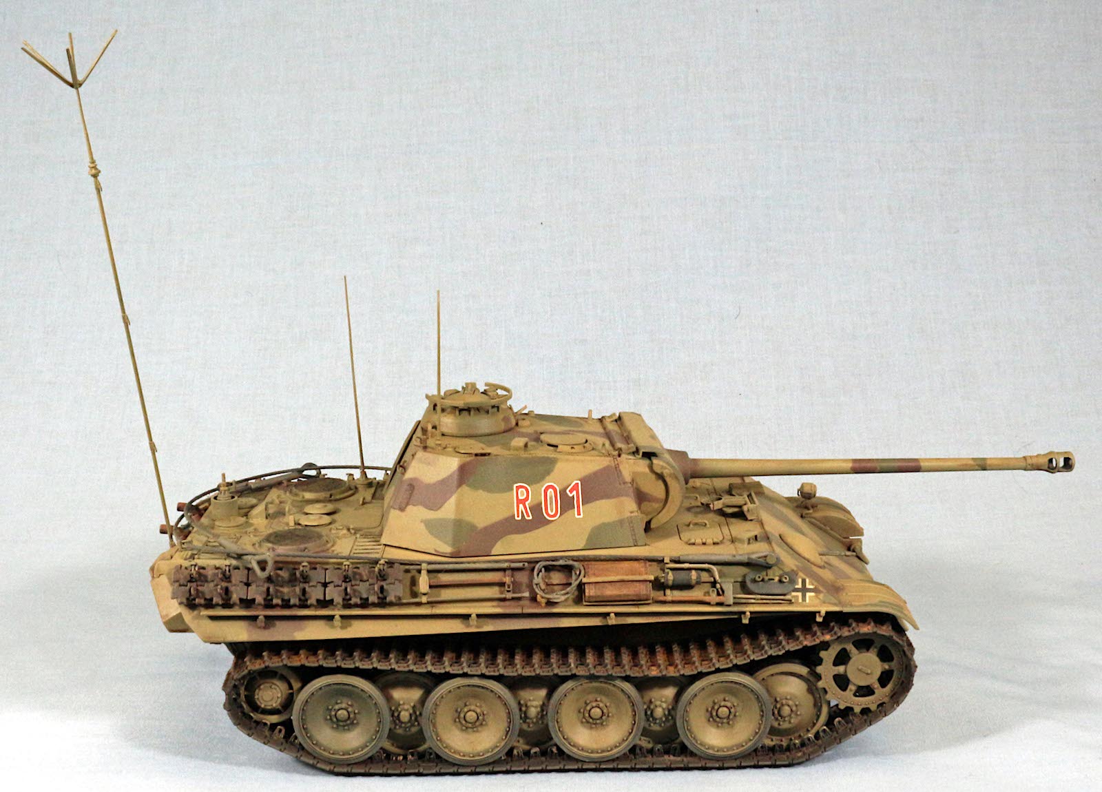
Befehls Panther Ausf. G
Dragon has recently released the Befehls (Command) version of the Panther Aufs. G. This kit is a fairly extensively equipped with many parts trees, clear, photoetch, and wire cables. Though externally identifiable at distance as a Panther, there are subtle details closeup that identify this as a special version of the venerable combat variant. Germany has a history of command versions of many of their combat vehicles, primarily equipped with extra radios and operators for long range and multi-command and control networks. This kit brings into the fold another variant of one of those vehicles.
Background
The Panther version of the Panzerbefelswagen was primarily derived from vehicles returned for repair or refit. From May 43 to Feb 45 up to 329 Panther Aufs. A and Aufs. G vehicles were converted to Panzerbefelswaqgens used primarily as Battalion and Regimental Command vehicles as well as air ground liaison. The main differences in the befels variants was the retention of the KwK42 L/70 main gun. The coaxial machinegun and ammo were removed. An additional radio was installed, with a corresponding reduction in main gun ammo stowage. The FuG5 radio was in the turret and a FuG7 or FuG8 in the hull upfront next to the driver.
Opening the Box
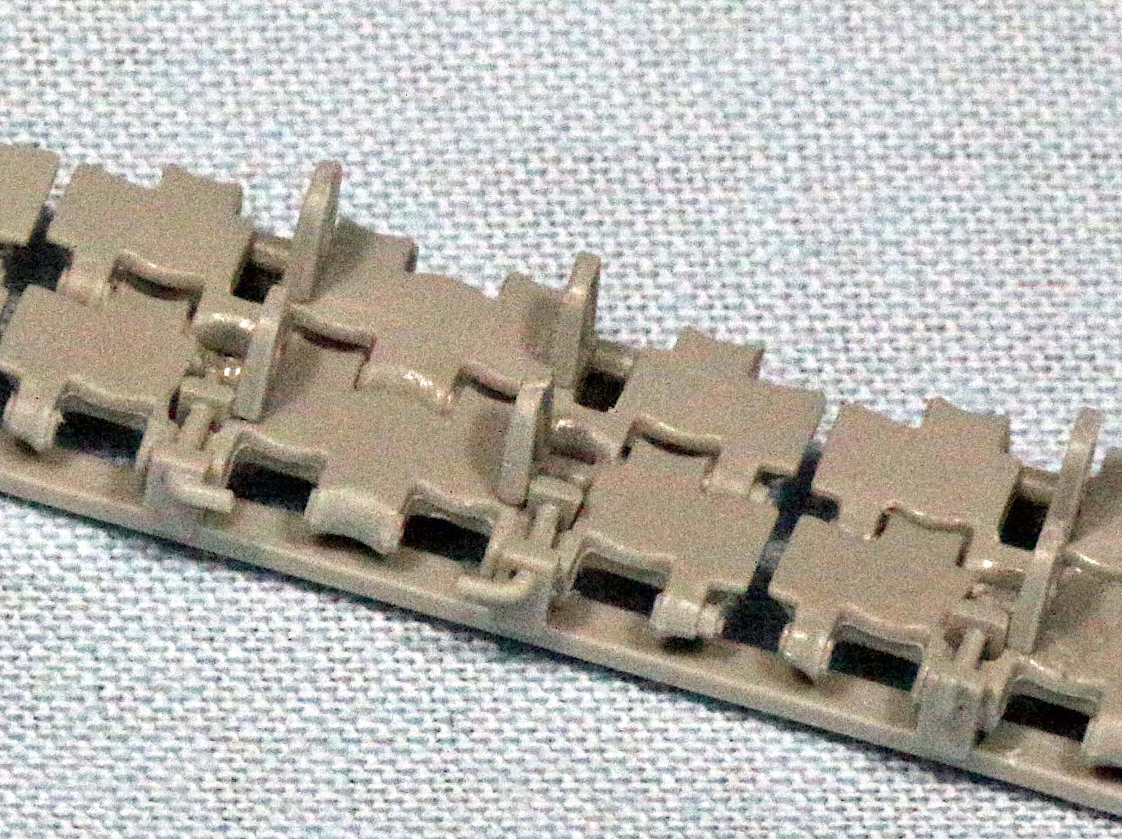
There were 12 individual poly bags containing 21 soft grey sprues. Tracks are DS and separately bagged. Several sprues consisted of individual antennas including the reversed conical elements, PE parts, cables, clear parts, and decals. The parts were tightly packed but no parts appeared to be warped including the very fine antennas. It was evident that this kit consisted of parts for multiple versions of other Panthers as at least 3 gun mantlets were included as well as more than the required road wheel arms and other suspension components. I counted parts and estimated that there were around 458 parts included. You will have a lot of leftover parts for the parts bin as you will not use them all. There was an 8-page instruction sheet printed in blue and black on white paper. There are 17 assembly steps with multiple subcomponent assembly steps like for road wheels, suspension components, pioneer tools, deck components and such.
Sorting Through the Sprues
There were 4 “E” sprues with suspension components, 2x “A” sprues with back deck pieces and the rest of the sprues are single’s that cover multiple assembly steps. There are two braided steel cables that are for the coiled-up cable loop and a 400mm cable for the two tow cables. This must be cut in half, but use caution and have a sharp pair of wire cutters since the cable will crush and flatten out, if you can’t cut it through in one motion. There are two PE sheets. One is for the back deck grills and one for cupula parts (that are for an optional variant)
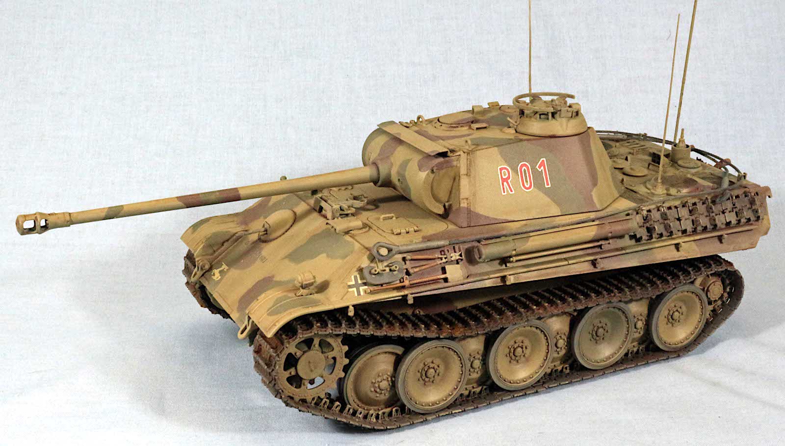
There is a small decal sheet printed by Cartograf/Italy, but only two color schemes, one for an unknown unit in Germany 1945 and the other for the Falschirm Panzer Division “Herman Goering” in Germany 1944. The colors are DunkelGelb, RedBrown and Khaki Green. Paints called out are GSI Creos Aqueous Hobby Color, Mr. Colour, and Model Master.
The Instructions
The instructions are generally very good and any unknown parts called out by number but unidentified by sprue callout can be located from the sprue layouts on the first page. There are a multitude of “Options”. Many suspension, back deck, hull and turret assemblies have variations using alternate parts. These are called out by a blue and white double arrow symbol on the sheet. Pay close attention to those as it matters when you remove parts since many of the parts are very close in appearance but with subtle differences. Not all bumper springs are the same. If you “Tag and Bag” components for organizing your builds, these callouts will help with the build, since you will already have the correct parts cut off the sprues for assembly.
Things to Consider Before Building
The suspension of the Panther has the left side suspension arms facing forward and the right side facing to the rear (like most modern armor). The road wheel arms look almost identical. If you remove the arms from the sprues, mark them with a sharpie with dots so you don’t intermix them. There are bump stops for each one and they won’t line up if the sides are reversed and the suspension will not be able to be leveled.
The torsion bars of the road wheel arms are anchored in the opposite side hull by a special cap arm that spans the interior of the hull and anchors on the adjacent housing. Parts E1 and E8 are the culprits so pay close attention to the smaller diagram in Step 2 as these show positioning of the arms and anchors. Be especially careful of which side of the diagram is forward. Step 2 is critical for getting the suspension to look right
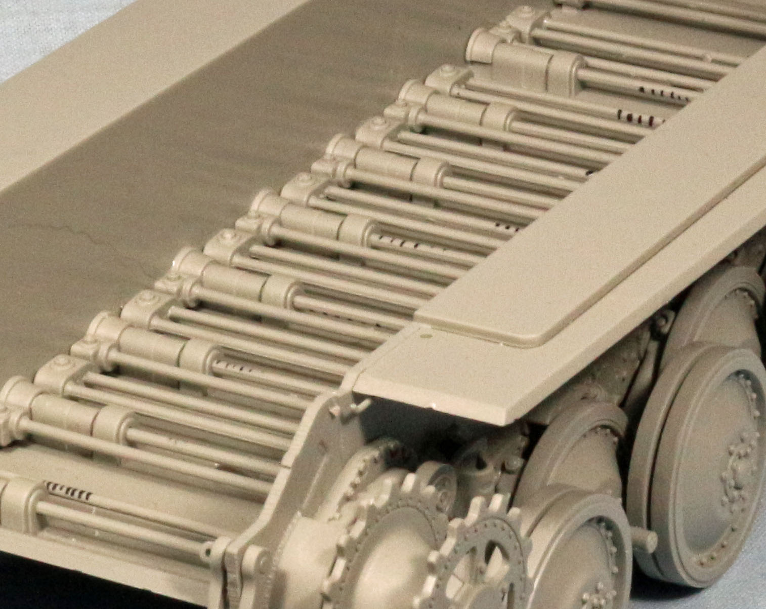
The Road wheels are somewhat difficult in the fact that they are separated by inner pairs and outer pairs. The inner pairs ride inside the track guides and the outer pairs ride outside the track guides. The inner wheels of the outer pairs must be placed first, then the inner pairs, and then last the outer wheels of the outer pairs. These essentially interleave and if you put the first set of outer wheels together first, you can’t get the inner pair inside. Leave the outer pair wheels off entirely, paint them separately as once the wheels are installed, there are places you cannot get access to for painting, even though you can see them. These are a tight fit. I can’t imagine the actual crews doing maintenance on this setup. You would have to pull the adjacent wheels to get to the inner pair to fix bearings or replace damaged wheels. So, put Part E12 inside, then put Assembly “B”, on then leave Part E10 off for painting and later assembly after painting and before the track is placed.
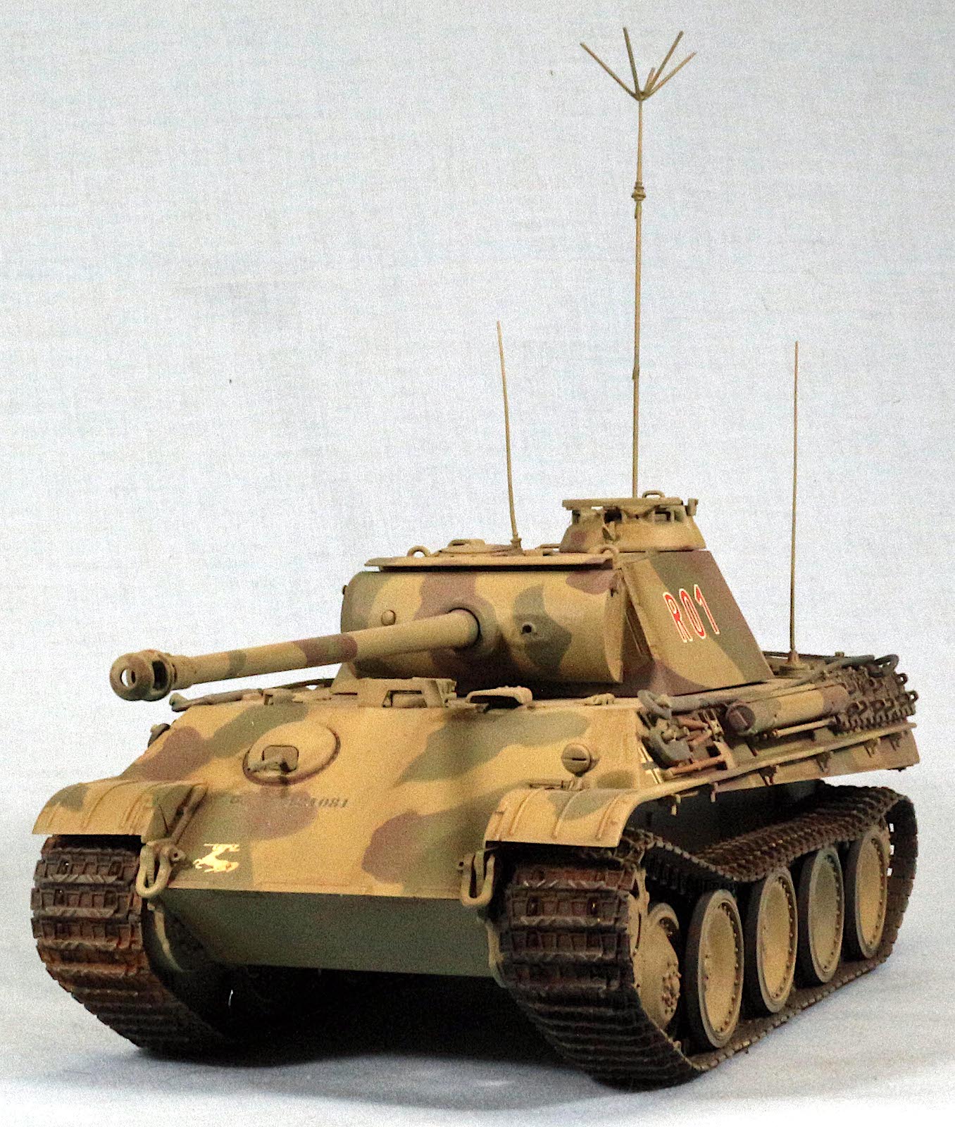
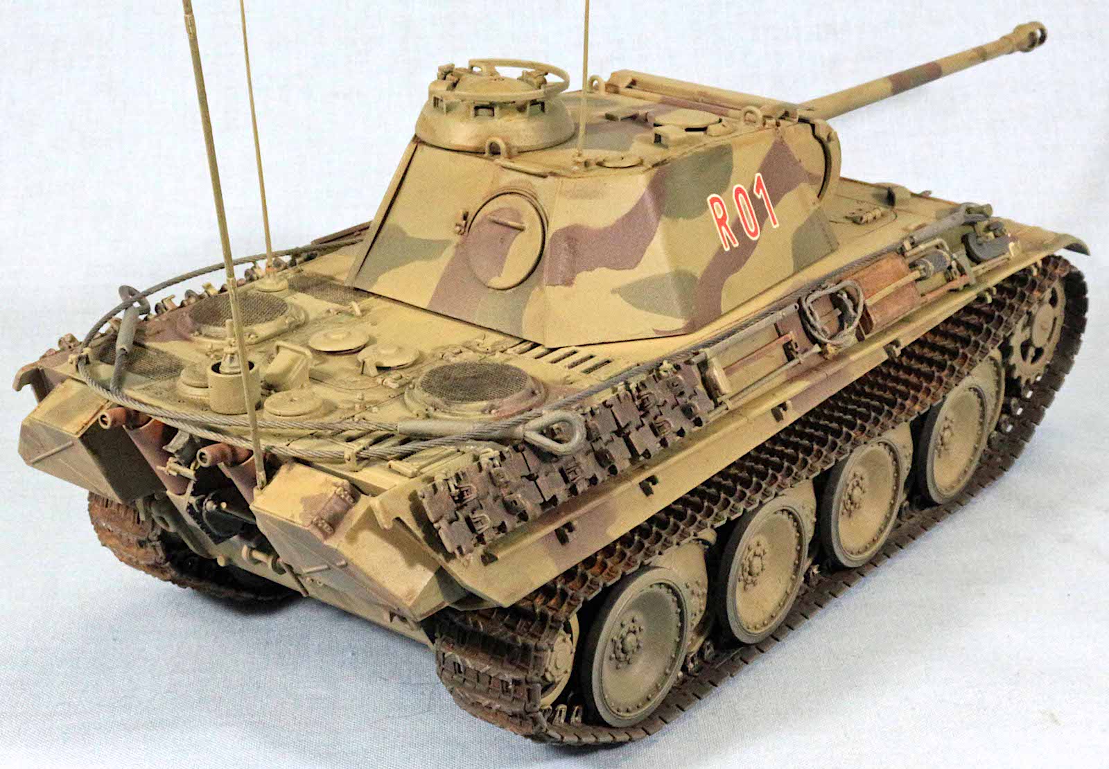
There are three antennas in this variant. One whip on the forward back deck, one whip on the turret and the reversed conical element antenna can be either placed on the back deck or on the right rear stowage box with the longer antenna poles. These all have a selection for antenna and mount or some sort of cap. Make those choices early.
The Build
Lower Chassis, Running Gear and Fenders
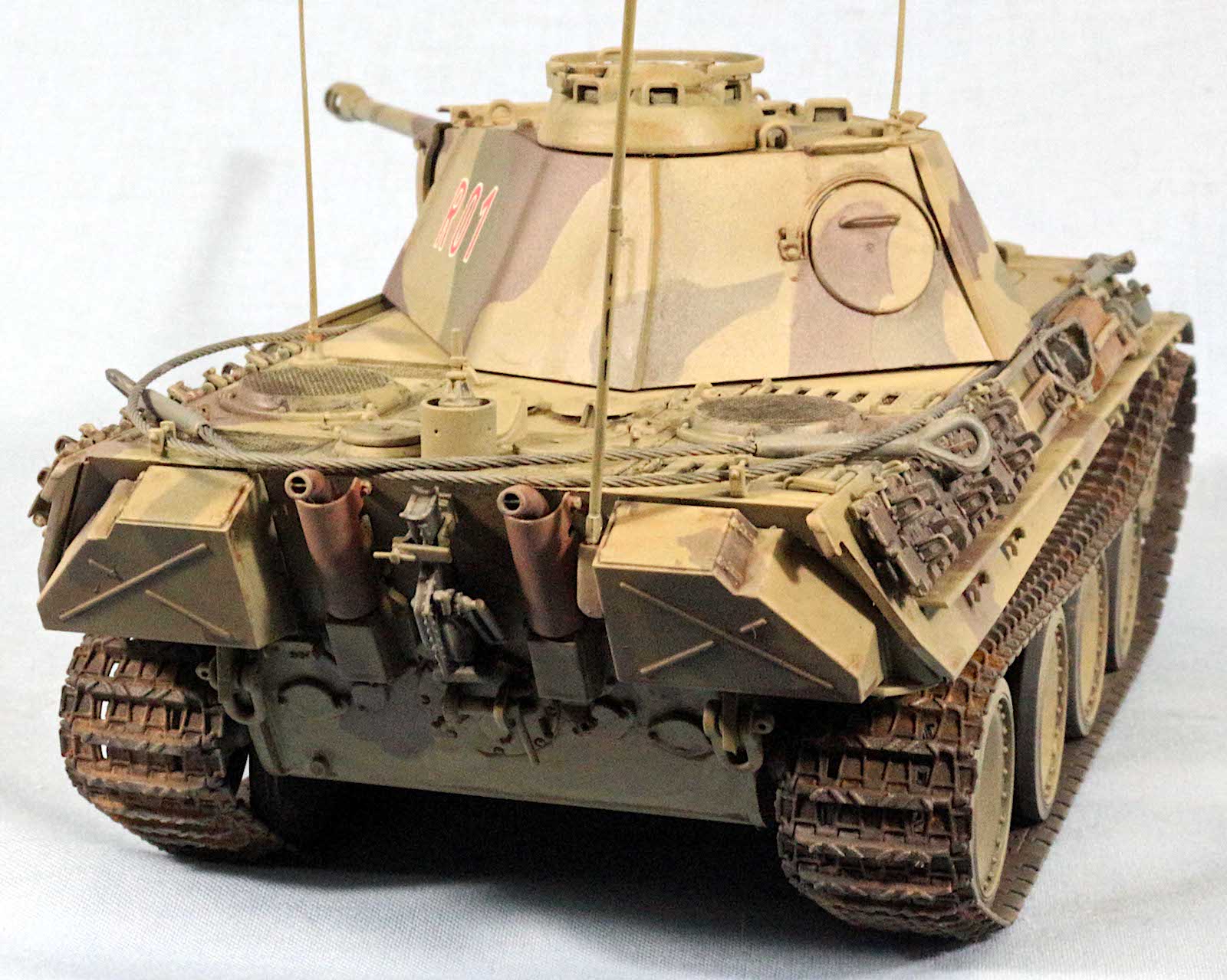
Steps 1 thru 5 deal with everything that is below the hull and rear deck. This also includes the rear hull which is a separate assembly. All parts will need some finishing where the sprue connections are. I used a “God Hand” sprue cutter (https://www.amazon.com/God-Hand-Spn-120-Ultimate-Nipper/dp/B008S51O22) and got pretty close in most cases. Some parts were almost cut too smooth, but the road wheels all needed some removal and clean up. Assembly was straightforward after making the variant decisions mentioned earlier. In Step 3, assembly A from Step 1, I painted flat black since this will be under the back deck grills and PE so it needed to be dark as to not show through. In step 4, the exhaust stacks consisted of 4 parts for each of two assemblies yet the track jack which mounts between the exhausts had 7 parts by itself. In general, no surprises and all parts had locator pins and holes that seems to line up perfectly, except when dealing with small parts and uncooperative tweezers. Testor’s Black bottle liquid cement was used mostly since strength was needed and some time for final alignment was desired
Front and Rear Decks, and Upper Hull
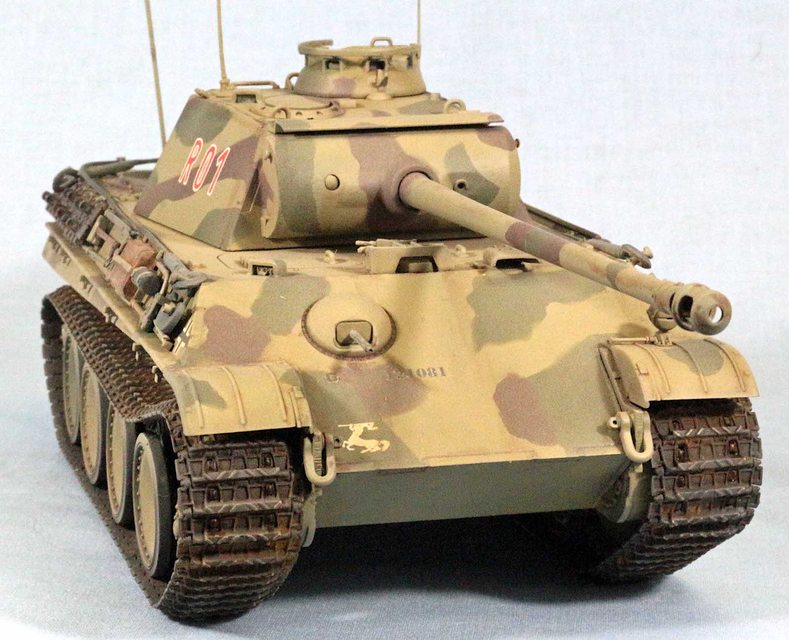
The same comments about fit and sprue clean up apply here as well. Some of the parts are too small to sand, so a sharp blade was used to do some trimming and after primer, slight imperfections will either be hidden by paint, or the exposed portion would be hidden. I built the vehicle with closed hatches to speed things along. There is enough detail if you wanted to do a diorama. I installed the vision blocks and applied liquid masker, and keeping my fingers crossed that I can get it off after painting. In stop 6 assembly J, the hull ball mount machinegun assembly was a bit tricky. Part C56 is held in place by Part C10 but there is not a lot of surface area to glue it in place. Part D10 also glues onto Part C56 from the outside. You will end up gluing everything in place once you get it all positioned. The machinegun barrel has a locator pin on D10 and I attached that once the ball mount was glued into the front hull. This is fragile and may not survive several bumps, but so far has held up well. Step 9 is the back deck final assembly of PE and radio antennas/mounts. Pay attention to Part C41. This is a bracket that has a pin going through two holes at the top (yes this is actually molded in and was flash free). The pin Part C31 should be left off at this time since the tow cables are draped through this assembly in both options in Step 17. Look ahead as I glued the pin in and there is only one option for routing the tow cables. I had to thread the raw cable end through the u-bracket with the pin at the top before I glued the tow cable end on the wire cable. This was a bit goofy to handle until I got the wire rope glued to the deck.
The spare track blocks were a bit of a pain, since they each had 3 parts, the block and two track guides (which were really small to handle and made more difficult as there was molded detail on one side). The guides had pins and the blocks had locator holes but the actual surface area was small. I ended up having to hand manipulate the top track block sprocket holes. The mounting bracket that attaches to the hull Part (C39) also has pins that hold the track to the bracket. The sprocket holes had to be opened and contoured to get the pin to lock the track in place just like the real thing. This really defines the level of detail that exists through the kit. The spare track blocks and bracket were almost a kit by itself.
All the pioneer tools and other containers went together well and attached nicely as there were subtle location devices for placement. The only really bad thing I experienced was in step 10, the 100mm wire rope that was to be wound around Part C15 on the right side sponson. The shorter piece of wire rope was very stiff and could not be looped around the bracket. The thing ended up being superglued to itself in multiple places and looked awful. I was too far in my attempt and I was beyond the point of no return since it would have destroyed the part. Dragon could have done a molded plastic cable coil or used something besides real stainless steel wire rope for the cable. I would recommend that you just glue the C15 bracket in place and not bother with the wire cable.
The Turret
The turret was rather unadorned, but still has a lot of detail. The main goal of step 12 was to assemble the gun mount tube and mantlet. The tube is a single molded piece, part (B6), which is glued between Parts B1 and B2. There is a lug on the tube that indexes at a point that is notched in both the mating parts, so if the tube doesn’t feel like it is not seating, rotate it a bit and it should drop into the slot and B1 and B2 should mate securely. Mounting the gun assembly into Part B22 is fairly simple, but you have to make sure the mounts get glued securely to Parts B31& B32, but also seats deep enough to get the mount out in front to secure the mantlet.to the gun tube. In building the exposed portion of the commander’s cupola, I went with the two-part variant, just Part H and B50. This avoided the PE parts attached as 5 separate pieces. I mounted the vision blocks but painted liquid masker on them before gluing them in place. In Step 13 There is a callout for drilling a hole from the inside the turret roof. This is needed for an antenna mount. It is subtle and you could easily overlook it.
The assembly of the deck to the hull is simple and is a great fit. If anything, it is a bit tight at the front glacis. It leaves a very fine seam that glues well. However, make sure the sponson top is glued and clamped to the sponson bottom (which is attached to the hull) and it is aligned otherwise you could get warpage that will make the suspension uneven and warped across front to rear. I had to make adjustments halfway through gluing as one side was attached and fitted tighter than the other.
Special Note: I wanted the reverse conical element antenna to be mounted to the right storage box on the rear of the hull. This antenna had a longer pole Part (P1) that makes an impression when on display. The mount, P2 was too small and fragile to even hold the item, so I fabricated a mount from styrene stock and drilled a No. 62 hole which was the same diameter of the P1mount pole. I reduced the end of P1 to fit the hole. Though not as accurate as the kit parts, it could easily represent a field modification since the mount is so fragile, and could easily have been damaged. Is just looks cool with that antenna way above the turret height.
The Track
The two runs of DS track in this kit are very thin and beautifully detailed, and assembly was a snap. Once each run was painted and weathered, I glued the ends using Tamiya ‘green top’ thin liquid cement. To get the correct track sag, you need to use Testors black bottle to get enough glue to get into the track to glue everything down solid on the road wheels. You have to wedge items to get the proper sag since the one piece track doesn’t sag. This will be an exercise in finding appropriate things of the correct diameter since the sponson actually slopes down to the rear idler wheel so it’s not an even run.
Painting and Finish
Primer and Pre-Shade
I started by applying a primer consisting of Krylon Color Master with Durable ColorMax Technology rattlecan (Flat Black) paint. This was recommended to me by our club Vice President for simplicity, great thin coverage and quick drying time. I left it to dry overnight to make sure it was fully cured.
Airbrushing Mission Models Acrylics with a Harder and Steenbeck Infinnity Airbrush
Since my return to modeling I have been somewhat handicapped by lack of a good airbrushing setup and a good air compressor. So It was time to splurge. I had researched many airbrushes on YouTube and narrowed down my search to a couple and decided to go with the Harder and Steenbeck Infinity. It comes with two nozzles and needles (.15mm and, .4mm) and has a quick clear feature that allows you to set rear travel limits on the double action trigger so you have finer control of the paint for fine work, but you can release the travel stop to clear the tip and then push a detent to return to the previously set stop.
This was my first foray into painting with a new airbrush and my second foray with acrylics. However the paint was different than the first encounter. The Mission Models Paint (https://www.missionmodelsus.com/) is much different than the Vallejo. The paint is very thick and requires a different thinning ratio. They recommend 2-3 drops of thinner to 10 drops of paint and also a Polyurethane intermix agent that acts like a reducer (1-2 drops to 10 drops paint). In a nutshell, even though this is an acrylic paint, it almost sprays just like Model Master Enamel. Has very good coverage and is more opaque than other acrylics. The paint sprays with almost no tip dry and the paint seems to just go on and on. I think I completely coated the Panther with 30 drops of paint (hull and turret). So once I started, I realized the .15mm tip was in and I changed to the .4mm tip to get the faster coverage after the first paint cup finished (doh!). You should also use their thinner and polymix as they are designed to work together. Their thinner is more active, so you don’t need as much compared to other manufacturers.
Camouflage
I started with covering the Krylon primer with the Mission Models Paint (MMP) DunkelGelb MMP-011. Once complete I let it dry overnight. My first attempt at starting the camouflage was to use the MMP Olivgrun MMP-009 and hand spray the pattern. That was not good judgement on my part since this particular vehicle actually had a very sharp color demarcation with little overspray, and my lack of experience with the new airbrush was less than desired. I resprayed the Dunkelgelb and dropped back 5 yards and punted. I reassessed the desired result and decided that I needed to mask. Instead of using tape, I got a tip to use “Panzer Putty”. This is interesting stuff. It is very like Silly Putty, but does not leave a residue and does not stick to anything but itself. I let gravity work the draping and did some shaping to get the pattern I wanted and then just sprayed the coat. Once the green was down and dry, I tackled the Rotbraun MMP-012. The Instructions as a painting guide was incomplete. There are no right side views or top views, so I used the box art as a right side guide and just winged it for the top. I tried to balance the distribution so all three colors were close to being evenly spread across the surface area.
Decals
I let the paint dry and then sprayed Pledge Floor Care-Multi Surface Finish (Long lasting shine and Acrylic Protection) more commonly referred to as “Future”. This was the decal prep coat to give the decals a good surface to adhere to the model. That dried overnight and then the decals went on and I used Micro Set/Micro Sol Red/blue two-part system to adhere and conform the decals to some of the irregular surfaces. I then added another coat later to seal the decals and to ensure a glossy surface for the washes and other weathering treatments.
Details
I painted the pioneer tools and other equipment before applying any washes and things to make it look grimy. This step actually was done between the “Future “coats.
Weathering
After the final gloss coat, I applied Vallejo Model Air 71.027 Light Brown as a dust coat to dull some of the gloss finish and to tone down the colors a bit. This also put a surface that would take some filters more easily. A final matt coating (Vallejo 70.520) was used to get the last traces of the gloss finish. This pretty
Conclusion
This Panther variant is an interesting addition to any enthusiast’s collection. The fit is precise, mostly clean from flash, and if present is very minimal. The sprue connections are very prevalent and will need to be cleaned from most parts. This is problematic for the finer parts like the antennas and the locking pins and some of the smaller detailed parts. A sharp No, 11 blade is essential. Paying close attention to the instructions will help make part and build decisions before you have the wrong combinations of parts removed from the trees. I had a fun time building this kit because the engineering is so precise it makes it essential that I put the time into this kit out of respect for the engineering effort that went into its production. This kit is appropriate for intermediate to advanced builders but since the fit is not complicated, advanced novices could also build this kit with help from an experienced modeler.
I would like to thank Dragon Models for providing this kit for review, and to IPMS USA for giving me the opportunity to review it.


Comments
Add new comment
This site is protected by reCAPTCHA and the Google Privacy Policy and Terms of Service apply.
Similar Reviews