
A-10C Thunderbolt II
Brief History From Wikipedia
The Fairchild Republic A-10 Thunderbolt II is a single-seat, twin-turbofan, straight-wing, subsonic attack aircraft developed by Fairchild Republic for the United States Air Force (USAF). In service since 1976, it is named for the Republic P-47 Thunderbolt, a World War II-era fighter-bomber effective at attacking ground targets, but commonly referred to as the "Warthog" or "Hog".[4] The A-10 was designed to provide close air support (CAS) to friendly ground troops by attacking armored vehicles, tanks, and other enemy ground forces; it is the only production-built aircraft designed solely for CAS to have served with the U.S. Air Force.[5] Its secondary mission is to direct other aircraft in attacks on ground targets, a role called forward air controller-airborne; aircraft used primarily in this role are designated OA-10.
The A-10 was intended to improve on the performance and firepower of the Douglas A-1 Skyraider. Its airframe was designed for durability, with measures such as 1,200 pounds (540 kg) of titanium armor to protect the cockpit and aircraft systems, enabling it to absorb damage and continue flying. Its ability to take off and land from relatively short runways permits operation from airstrips close to the front lines, and its simple design enables maintenance with minimal facilities.
The A-10 served in the Gulf War (Operation Desert Storm), the American–led intervention against Iraq's invasion of Kuwait, where the aircraft distinguished itself. The A-10 also participated in other conflicts such as in Grenada, the Balkans, Afghanistan, Iraq, and against the Islamic State in the Middle East.
The A-10A single-seat variant was the only version produced, though one pre-production airframe was modified into the YA-10B twin-seat prototype to test an all-weather night-capable version. In 2005, a program was started to upgrade the remaining A-10A aircraft to the A-10C configuration, with modern avionics for use with precision weaponry. The U.S. Air Force had stated the Lockheed Martin F-35 Lightning II would replace the A-10 as it entered service, but this remains highly contentious within the USAF and in political circles. With a variety of upgrades and wing replacements, the A-10's service life can be extended to 2040; the service has no planned retirement date as of June 2017.[6]
The Kit Contents
Parts - there are a total of 230 parts on 11 light grey plastic sprues, many of the sprue are bagged separately. .
Clear Parts - the are three clear plastic sprues, with the canopy and windscreen as separate parts allowing the builder to pose the canopy open or closed.
Decals - there are three sheets of decals for four different aircraft, plus weapon's markings.
Instructions - a twelve page book format covers the construction, with ten steps shown as line drawings with part numbers called out as well as paint colors. Page 2 cover the parts sprue layouts. If any parts are not to be included in the build they were not noted, and therefore the modeler will need to follow the instructions closely.
Part 7 shows details that need to be removed. I found these directions not very clear, but was hoping that once I started the actual assembly I would determine just what was required.
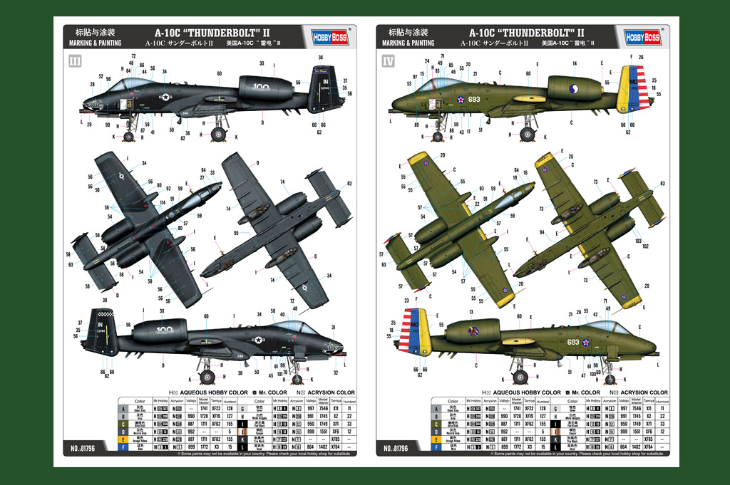
Also included are full color glossy prints for each of the four aircraft, plus weapons images showing the colors and markings placement. Paint and color legends are provided based on several of the more popular paint manufacturers.
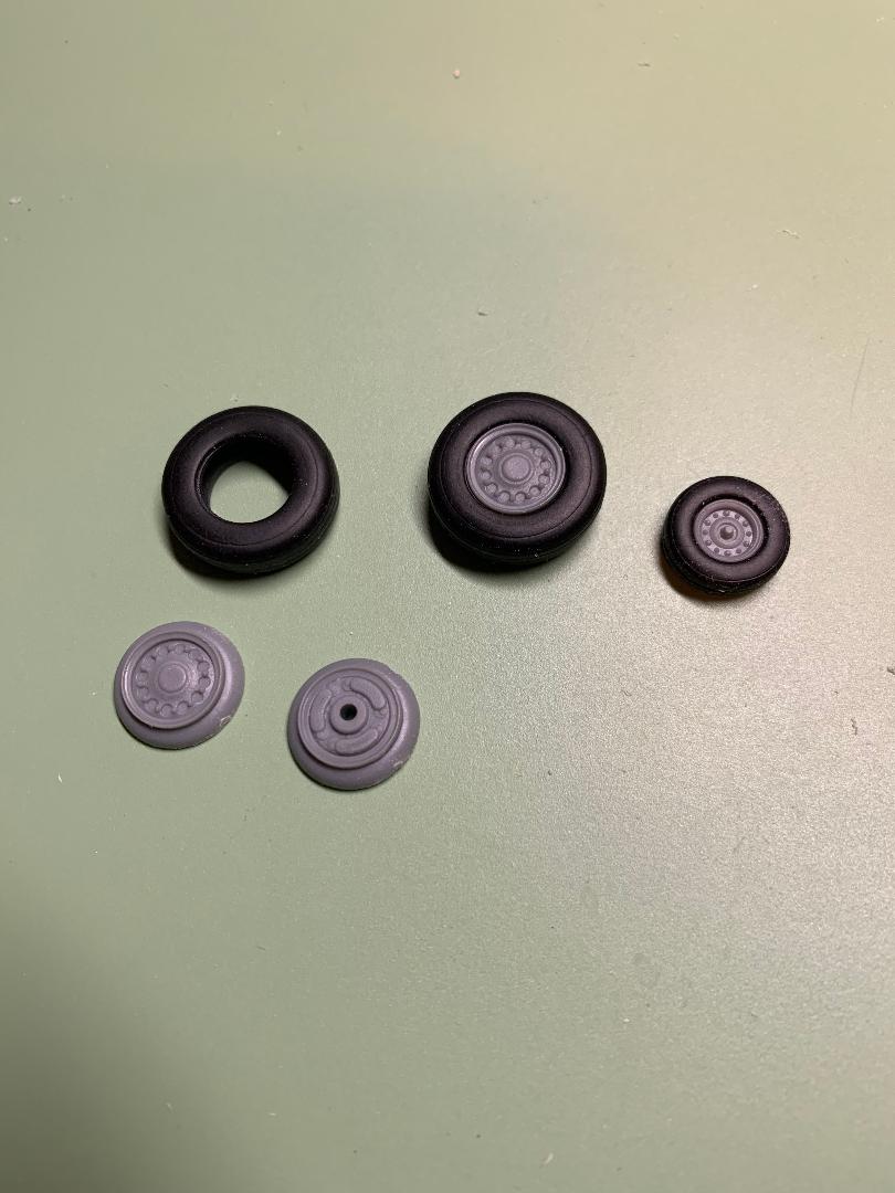
The landing gear wheels include separate black rubber tires.
Construction
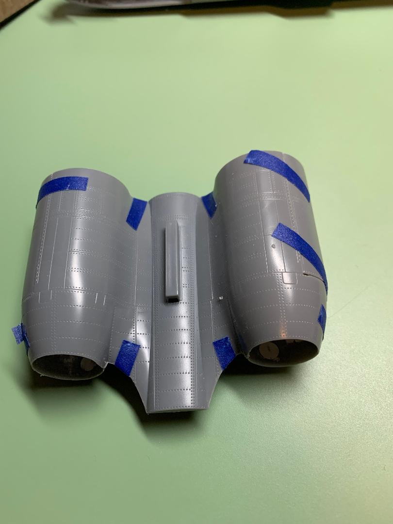
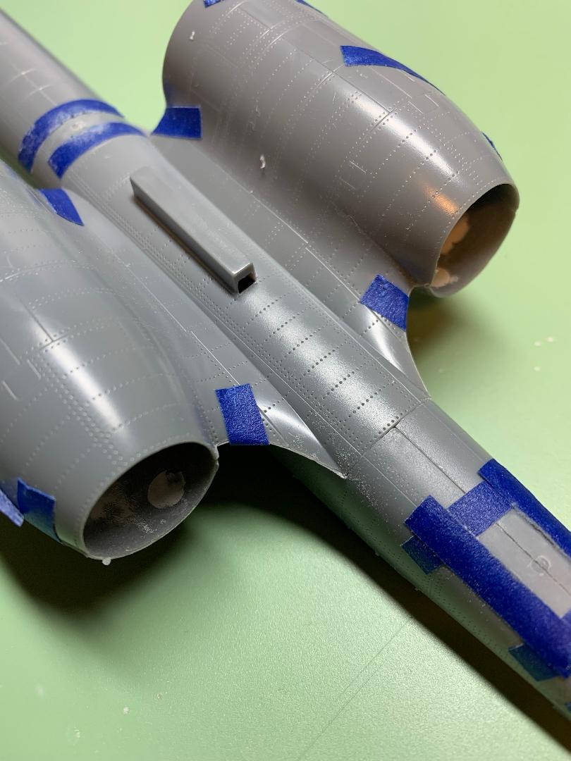
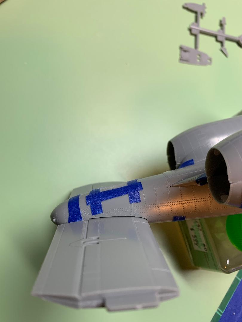
Many of the images included in this review have parts held together with blue tape and the parts are not glued together or joins and seams filled. The visible gaps will be addressed in the final assembly.
Cockpit/Ejection Seat
The ejection seat is just three parts and was set aside for painting after it had been assembled. The cockpit tub is comprised of three parts (floor, rear bulkhead and front three-sided surround) with the cockpit itself trapped inside. The cockpit will not fit in the tub if the tub is assembled first. I left the control column and instrument panel off until after everything was painted.
At this point I moved ahead to step 6 and assembled the rear cockpit deck
I airbrushed Tamiya XF-85 on the ejection seat, cockpit assembly, control column and instrument panel. I thinned the paint with 93% isopropyl alcohol..
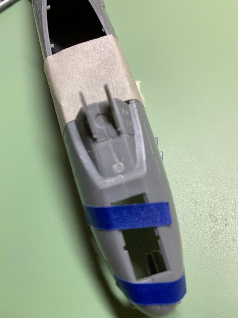
GAU Gatling Gun
This assembly was probably the most challenging part of this build. The instructions were not always clear to me as to exactly where the parts fit together, so much test-fitting was required before the parts were glued together. I planned to leave this assembly out of the models after all the effort that I put into it. Beside it looked like a real challenge to paint. Why hide it after all that work and effort?
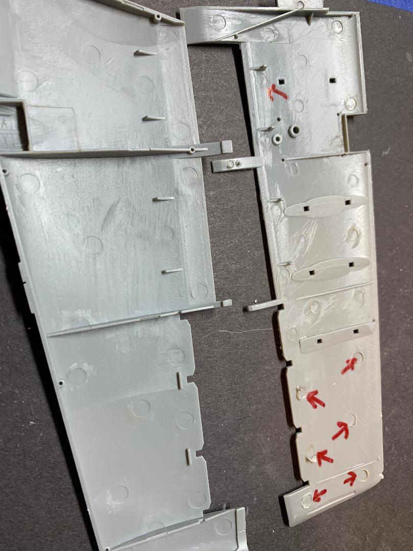
Wings
The wings are each made up from two halves (top and bottom), plus several two part moveable surfaces. The main wing parts have several ejector pin marks with raised rims. Test fitting revealed the raised rims needed to be removed in order for the wings to fit together properly. A dry test fitting of the assembled wings showed the wing tabs to be slightly too large to fit into the fuselage slots. The tabs were thinned slightly to improve the fit.
The moveable surfaces are each made from two parts each. All went together well.
Landing Gear/Wheels
The nose gear well is made up from three parts and needs to be painted prior to installation in the front fuselage otherwise the nooks and crannies would not be accessible for painting. The same went for the main gear wells. I first primed the interior surfaces with Tamiya flat black, and when that had dried I airbrushed Tamiya flat white followed by gloss white onto the interior surfaces.
The main gear wheels are each made from two plastic hubs plus rubber tires. Once the two hub halves are glued together they must be inserted into the tire. This is a snug fit and no glue was required to hold the plastic to the rubber. The nose wheel is a single plastic part plus the rubber tire. Fitting these parts together was even more of a challenge. The fit was snugger than snug, but they did fit together.
The landing gear were primed flat black then over-sprayed with flat white followed again by gloss white.
Fuselage
I added short pieces of styrene shapes to the inside bottom surface of the fuselage to allow a better fit when the two halves were fitted together. I airbrushed the nose gear well flat black as well as the interior of the cockpit area. I then airbrushed the nose gear well white and hand-painted the various details.
Once the painted cockpit was glued in place I added plenty of weight behind the cockpit for the finished model to set properly on the landing gear. I taped the fuselage halves together, fitted the wings, tail and engines in place to check the balance.
when it came time to fit the fuselage halves together I proceeded first along the top, using tape to hold the parts together while the solvent cured. The top fit together fairly well, while the bottom seam required a bit more attention for a tight fit without any significant step between the sides.
The join at the nose did require more attention to get the parts to fit together. The join at the gunsight and the forward area below the windscreen required some filler and sanding to eliminate a noticeable depression.
Engines/Exhausts
I am not familiar with the interior components of the engines so I will be as descriptive as I can to explain the assemblies. The engines and exhausts pods are each made from two halves, being open at both ends. The cowlings are attached to single piece drums, which in turn are fitted over the front of the engine pods. The inlet turbines in the cowlings are detailed on the exterior as well as the interior.
Once the two engine pods were assembled I set them aside to allow the solvent in the joins to dry and harden thoroughly. The exhausts were sanded to eliminate the seam lines as the rear section of the engines will be visible at the rear end of the engines' nacelles.
Next I dry fit the many parts of the nacelles together to check the fit of the parts. Parts C13 and C14 are designed to be either closed or left open to expose the engine details (if left open several ejector pin marks would need to be removed). I planned to fit the doors closed and found noticeable gaps on the bottom side that would need to be addressed. A fit of the nacelles assembly to the top of the fuselage revealed a problem with the fit: the assembly would not seat properly. I carefully shaved off some of the plastic from the rear of part C1 and the assembly fit near perfectly.
The engine exhausts were first painted with Tamiya flat black inside and out. I dry-brushed the exterior of the nozzle with Silver Rub-N-Buff for the metallic appearance..
Tail Assembly
This detail is shown in step 7 page 9. The first step deals with the removal of a blade antenna on part E3 (the top of the horizontal stabilizer), and the drilling of two small openings on the same part. The fit of all the parts was surprisingly good. I dry fitted the two vertical stabilizers to the horizontal member and noted that slight gaps appeared on both joins. Some minor sanding helped reduce the gaps, with a touch of acrylic putty finishing the job.
The tail assembly was next test fit to the underside of the fuselage and a noticeable gap was present at the rear join. This would be filled with acrylic putty during the final assembly.
Clear Parts
The clear parts are nicely molded with no flash. I dipped the canopy and windscreen in Future, not because they needed it, but because I normally do that. The clear seeker lenses on the AGM-65 and the GBU-8 were not used as I used Krystal Kleer built to a dome shape instead. I have never had good luck getting a good fit with domed lenses in earlier builds.
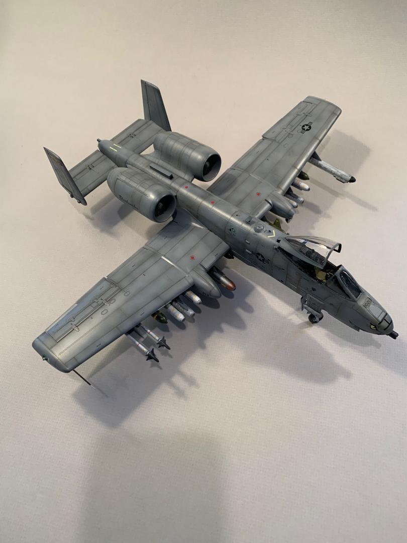
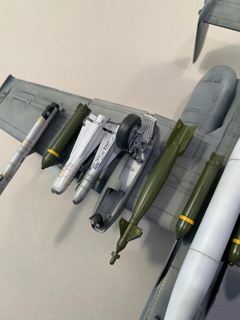
Pylons and Under-Wing Stores
There are four pylons per wing plus two fuselage pylons. The wings have recessed pockets to mount the pylons to for a good solid fit. A minor gap did appear around a few of the pylons but was easily filled with a touch of acrylic putty.
The underwing stores include AGM-65 Hellfire missiles (6), AIM-9L Sidewinder air-to-air missiles, (2) ALQ-131 ECM pods (2), Mk-20 Rockeyes (12), Mk-82 bombs (12), two MER's, one fuel tank, ALG-119 ECM pod, one AAQ-14 Lantirn pod, one AAQ-233 Sniper pod, two GBU-8 nd finally two GBU-10 bombs. The last page of the instructions include a diagram depicting various stores load. Mix and match, take your pick.
Painting the Exterior
I washed the model and weapons in warm water with a drop of Dawn detergent, scrubbing the surfaces with and old toothbrush to remove dust and body oils acquired during the assembly process. I set everything aside for a day to dry thoroughly.
Painting note: The exterior surfaces were prime-painted with Tamiya Flat Black (XF-2). I used Vallejo Model air and Model Color paints throughout the build finish colors. The Vallejo paints were thinned with their proprietary thinner and applied with an airbrush.
The previously painted cockpit and wheel wells were plugged with the black foam found with Eduard resin accessories. The engine intakes and exhaust were also carefully masked off to protect those painted surfaces.
Weathering
Reference images I have seen varying degrees of weathering on A-10's. Nothing significant of note. I used MIG Deep Grey panel line wash. I really did not appreciate the amount of detail and recessed panel lines until I started the pin wash process. Plan to spend several hours to complete this task if you want to accent the panels lines on this model.
Decals Application
Several months ago I had the opportunity to review the Two Bobs decal sheet 48-276 "Hoosier Hawgs" and felt this build/review would be a great opportunity to put that set of decals to use. I planned to use the kit decals for the various underwing stores and supplement the Two Bobs set where necessary.
Prior to applying any decals the model was given several light coats of Future floor wax. The final coat was allowed to thoroughly cure for 48 hours.
The cockpit was completed earlier in the build and the first decals to be applied were the side consoles and the instrument panel. My first hint of possible trouble was when I applied the second decal and one of the corners curled over itself and would not flatten out over the side console. Next, when I applied the instrument panel the same thing happened. Not only could I not get the decal to unroll, I could not adjust the location of the decal even slightly. This was troubling. The raised surface details I am sure contributed to the problem of trying to align the decals.
The kit decals were cut apart individually and dipped into water. Within less than a minute the decals separated from the backer sheet. I used MicroSet to position each decal and MicroSol to soften. the decals reacted well to both solutions and settled down nicely over the surface details. i applied various stencils to the underwing stores and had no issues. The formation lights are represented by yellowish strips: there was no surface detail to position those decals.
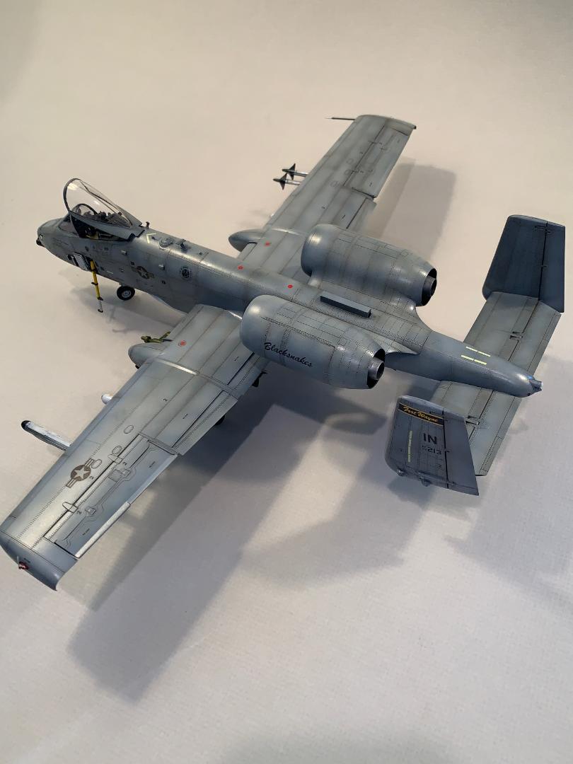
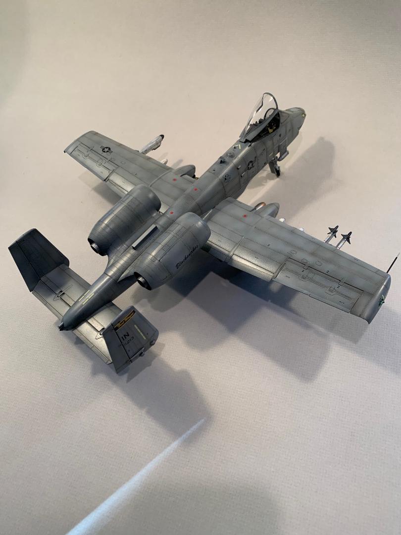
The Two Bobs decals offer marking for five aircraft, four all grey (FS 36118), and one black (FS37038) and grey (FS 36320). I used the marking for aircraft 79-0213, 163rd FS, 122FW, Fort Wayne ANG Base.
When the weathering and decals placements were completed the model with given a finish coat of clear satin.
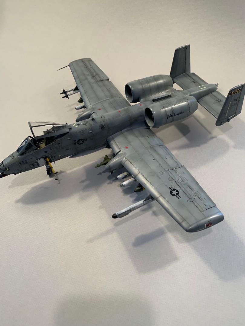
Bringing it All Together
The landing gear and doors were glued in place and allowed to cure for 24 hours before setting the model right side up.. All the underwing stores were glued in place and the canopy was fitted in an open configuration.
Conclusion
Test-fitting of parts is always recommended for any model. This rule is especially important with this kit. I found the mating surfaces of most parts needed some attention with a sanding pad to remove minor flash and some unevenness to allow the parts to fit together properly. Many parts do have minor bits of flash that would affect the fit of parts as well as appearance.
I would have preferred plastic wheels/tires rather than to plastic/rubber combination. The details and panel lines engraving are really quite nice and lend themselves to a nice panel line wash to punch out the details.
The kit decals that I used performed well, and if a modeler decided to build one of the schemes included in the instructions some care would be required to avoid tearing and folding of the delicate kit decals. The only issue i did have withe the kit decals I used was the occasional curling of one end. When that happened it was almost impossible to get the decal to lay flat. The decals responded quite nicely to MicroSet and MicroSol.
This is a nice kit, but it will take a little care and effort to get several of the parts to fit together and aligned properly. Even then I found some joins required filler and sanding to eliminate steps in the join.
I wish to thank MRC and IPMS USA for the opportunity to build and review this kit.


Comments
Add new comment
This site is protected by reCAPTCHA and the Google Privacy Policy and Terms of Service apply.
Similar Reviews