
Sikorski JRS-1 The Boat, Limited Edition
Thank you to the great folks at Eduard for reissuing and upgrading a kit of a unique Sikorsky flying boat for the scale modeling world. Thank you also to the IPMS Reviewer Corps staff members who do the hard work in getting us kits to review, the reviews posted, and the news spread to the world.
The Sikorsky JRS-1, or S-43, is similar in appearance to the famous Pan Am Clipper, the S-42. I did not know that several of these planes survived the Pearl Harbor attack, and went in search of the Japanese fleet immediately afterward.
Overall Summary
I enjoyed building this kit. It is a limited edition offering, with some unique challenges for the intermediate to advanced builder. A very nice set of marking options will allow you to complete a replica from nearly anywhere within the operational lifetime of the JRS-1. I am very pleased to have another yellow-wings example for my USN between-the-wars collection. A build log follows the conclusion and recommendation section.
Initial Impression in the Box
The colorful 15 x 9.5 x 2.75 inch box has a cover painting of 2 JRS-1 aircraft in yellow-wing livery flying along a tropical coastline suggestive of Hawaii. The box sides show kit contents and seven possible color schemes to choose from. An A-size, 16-page color glossy instruction booklet provides a suggested order of assembly. An excellent bonus is a 27-page historical background color glossy reference booklet in format similar to the instructions. This reference booklet might be worthy of a separate review!
Three medium-gray sprue trees have the bulk of the parts. There is a slight suggestion of mold release. The attachment points between the sprues and the parts are thick. Locating holes and pins are not present on most parts. Some ejector pin plugs are evident, but are generally not in places that are not visible after assembly. Surface detail is not too prominent. Part numbers are not on sprue trees, but are on a location diagram on page 2 of the instructions.
Photo etch parts are on a slightly magnetic 2 x 2.75 inch fret with color instruments, belt buckle pads, and other details in a zipper-closure poly bag. The PE is very finely etched and numbered. The decal sheet is 6.5 x 4 inches with markings to complete 1 of 7 aircraft, including red-yellow-blue prop tips, a “bow” glare panel, and walkways, all protected by a parchment paper covering in a reusable poly envelope. A clear sprue with round cabin ports, landing lights and a cockpit windscreen was also enclosed in a zipper-closure poly bag. Other items protected in polybags include the dark gray resin parts and a yellow, precut masking template. Broken resin parts were contained within the bag.
Instructions
The instructions are crisply printed in color on heavy glossy paper and follow the same color coding scheme used by Eduard on their photo-etch instructions sheets with regard to using the PE parts. Location arrows are usually accurate enough, but sometimes it is not completely clear where parts attach, for example, in step G. The attachment position of the splashboard, part 66, is not completely shown in final position. However, dry-fitting should clear up most issues that the instructions did not clearly describe.
Beautiful color marking guides with callouts for GSI Creos (Gunze) colors are found on the last pages. Part number maps may be found on page 2 along with a paint equivalency chart.
Construction
There are few positive connection points between parts; do not expect to find pins, sockets, and tabs to hold parts in place. You can also expect to do lots of drilling and pinning of struts and other critical lineups. This is not a criticism, but a caution. are advantages to this feature. I used more thick CA and accelerator than usual on this kit. Mold seams are common, but I did not have any difficulty removing them. Some parts were left with the seams in place to illustrate their size. The seams are not especially visible on the finished model.
I did not closely follow the suggested order of assembly. I found it helpful to build the kit in three major subassemblies: 1) main parasol wing with the center pylon, including the engines and wingtip floats, 2) the tail surfaces, and 3) the main fuselage. I added the support struts for the horizontal surfaces after final assembly. This sequence allowed me to completely add all the rigging to the wing and pylon, before final assembly. I was also able to mask and paint more easily. If you chose one of the blue-gray versions, this approach may not be quite as helpful.
The build log at the end of the review highlights the construction steps and adventures. More detailed and specific comments may be found there.
Decals
The decal sheet has markings to replicate one of seven aircraft completely. The decals have excellent opacity.
Two national insignia had bubbles that crushed and shattered on light contact while dry, but there are enough extras that the loss of the insignia did not cause a crisis! The black glare panel decal forward of the cockpit shrank into a raisin-like blob as it slid off the decal sheet. I couldn’t tease it flat, discarded it, and painted the panel later. That was the only decal that reacted this extremely. Some of the numbers tried to behave the same way, but were easily straightened out. I use Microscale solutions and surfaces were painted with Vallejo metal color or Testors gloss acryl. Future top coats sealed the decals nicely.
Propeller tip decals, in red-yellow-blue, are included for the front of the blade tips. A photo on p. 7 of the included reference booklet suggests red-yellow-blue tips on the blade backs, and the outer one-half to two-thirds also painted black. I raided the spares file and added red-yellow-blue decals to the blade backs.
Finishing
All interior surfaces are painted in zinc chromate or interior green, per the instructions. I found nothing to suggest otherwise in any of the kit references. I had some fun intentionally weathering and “blotching” the green interior surfaces. I did not have great initial success with exterior color adhesion. I washed the kit before construction in standard warm soapy water followed by a thorough rinse. Acrylic primer did not stick until I scrubbed the parts down with a soft toothbrush and Polly S plastic prep. I used very light-tack masking tape and Post-it strips.
Once the “peeling” problem was solved, I had no difficulties with painting. I found the subassembly approach to allow more effective masking and airbrushing. Whew!
Aftermarket
A separate photoetch upgrade set is available for this kit. That set is the subject of a separate review.
Conclusion
This is a very appreciated and unusual kit representing early USN aviation. I enjoyed the challenges presented throughout construction, however this is a kit for intermediate to advance builders. I do not consider myself an advanced builder, and a better skill set might have produced a better model. I was my own worst enemy on this kit, constantly breaking off PE parts and other fumblings about.
Thank you Eduard and the IPMS Reviewer Corps! As always, it is an honor to be part of the team.
Build log, per instruction booklet order for reference
- Initial review: Parts not needed are culled, RDF loop might be useful in 1:48 scale
- Initial review: Need cross planning with PE upgrade
- Initial review: Lots of pinning might be a good idea. No tabs or attachment guides generally, need to plan for shims and braces
- Initial review: Struts will likely require drillouts, will add fragile PE just before painting
- Initial review: looks like 3 major subassemblies: fuselage including wing pylon, wing, and empennage
- Initial review: Ex Sword kit, finely recessed panel lines
- Step A: all parts replaced by upgrade, but no seat cushion in pan and use kit PE belts.
- Step B: rudder pedals do not have any guide for placement. Overall detail seems somewhat soft, not crisp. Part 55 does not have a port as suggested on the instructions, is actually a dimple-like thing.
- Step C: Only a little bit of fiddling and filing here to get everything to stay together.
- Step D: The paint callouts for the seats are for gray frames and red-brown cushions. The seats are cast in opaque gray, so I only painted the cushions. I added the decal belts.
- Step E.1: Ditto painting in step D. Many of the armrests and 2 seat backs were broken off on arrival.
- Step E.2: Fill the two starboard port forward of the wheel well, and add a small port to fit one of the smaller clear part port glass pieces. A large port is drilled out and mounted aft of the starboard loading hatch between two existing ports. Port glass installs from the inside, not the outside. Passenger seat were removed from the pour plug with a razor saw and were glued to the compartment floor. I used triangular plastic gussets under the floor to make the cockpit bulkhead joint more strong (and square!).
- Step F: Panel detail was easily removed and the very nice color panel set added from the PE set included in the kit. The stern boarding access stair/companionway compartment went together well. If you mix up the stairs sides, the top edges of the sides are curved to match the camber of the stairs. Small gussets were added to strengthen the bulkhead-floor joint, since the tail wheel is mounted to the bottom of the floor. Port glass installs from the inside, not the outside. Quite a bit of flash removal from fuselage halves joining surfaces. I used some plastic strip to help align the halves. I also installed the control yokes after the fuselage halves were joined. Each half had a slight twist, but I was able to mostly line them up at the step, the tail, and the nose. I was able to make the top seams align. But the bottom seam where the hull chines meet did not “untwist” very well, however, this is a relatively easy (and less visible) seam to fix. The upper seams will be NMF whereas the bottom is black. I added a pin to the tail wheel assembly to allow it to be added post-painting.
- Step G: The overhead engine control panel is very nice. Like the other excellent cockpit details, unfortunately it will be difficult to see the detail unless a hatch or something else is open. All of the seam fitting was done before any exterior PE added
- Step H: The upper and lower wing halves are assembled in this step, with central details. The engines and propellers are assembled in this step. I did not use the spinners. The wing parts require careful line-up, and trailing edge thinning. I started with the center of the wing and glued outward to the tips. Make sure that the various components, such as the nacelle and light cutouts in the leading edge are lined up. I left the PE “stubs” on the tied-down ring (PE 7, 8) and drilled holes in the fuselage to allow a more positive attachment point
- Step I: This step is not labeled as “I”, but is where engine and nacelle detail is added. Leading edge landing lights are also included here.
- Steps J and K: the actual wing tips are added here. I drilled and pinned these to make the joints stronger. It appears the pylon can be mounted on the wing and the whole assembly attached to the fuselage post painting. This should allow all the wire rigging to be completed on the wing with a lot more room to work. I also added nearly all the PE detail here after painting. I found assembling the gear struts to be very challenging. I rebuilt or replaced some of the parts using extra white metal materials from aftermarket landing gear replacements for other aircraft. No locating points are provided in the wells for positive attachment and placement. Instructions show only a general sense of position. I used slow-cure, max-strength CA to position each strut assembly accurately. The reference book really helped with visualizing and final assembly!
References
- Adcock, A., 2008, U. S. Navy Flying Boats and Amphibians in World War II, Special Series, 6095 Squadron/Signal Publications, 80 p., ISBN 978-0-89747-556-3
- Johnson, E. R., 2010, American Flying Boats and Amphibians, an Illustrated History, McFarland & Company, 379 p., ISBN 978-0-7864-3974-4
- National Air and Space Museum collection
- Seawings website

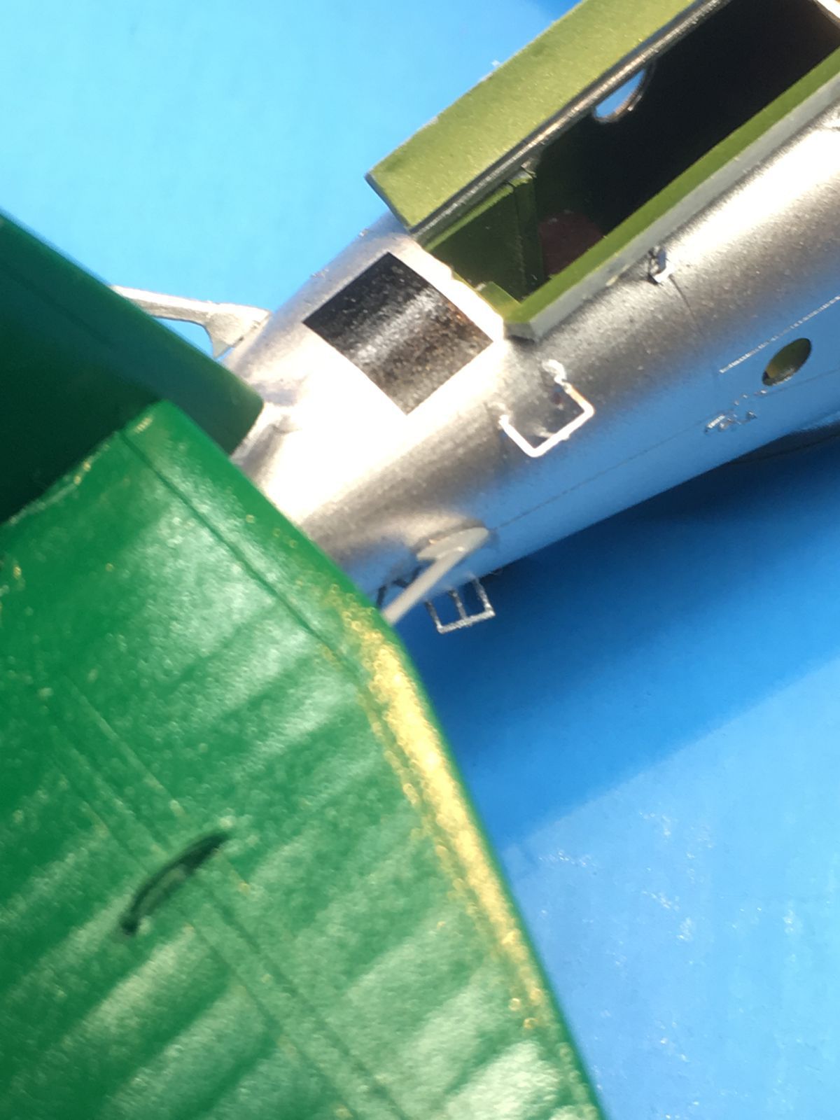
PE detail aft steps and open cabin hatch
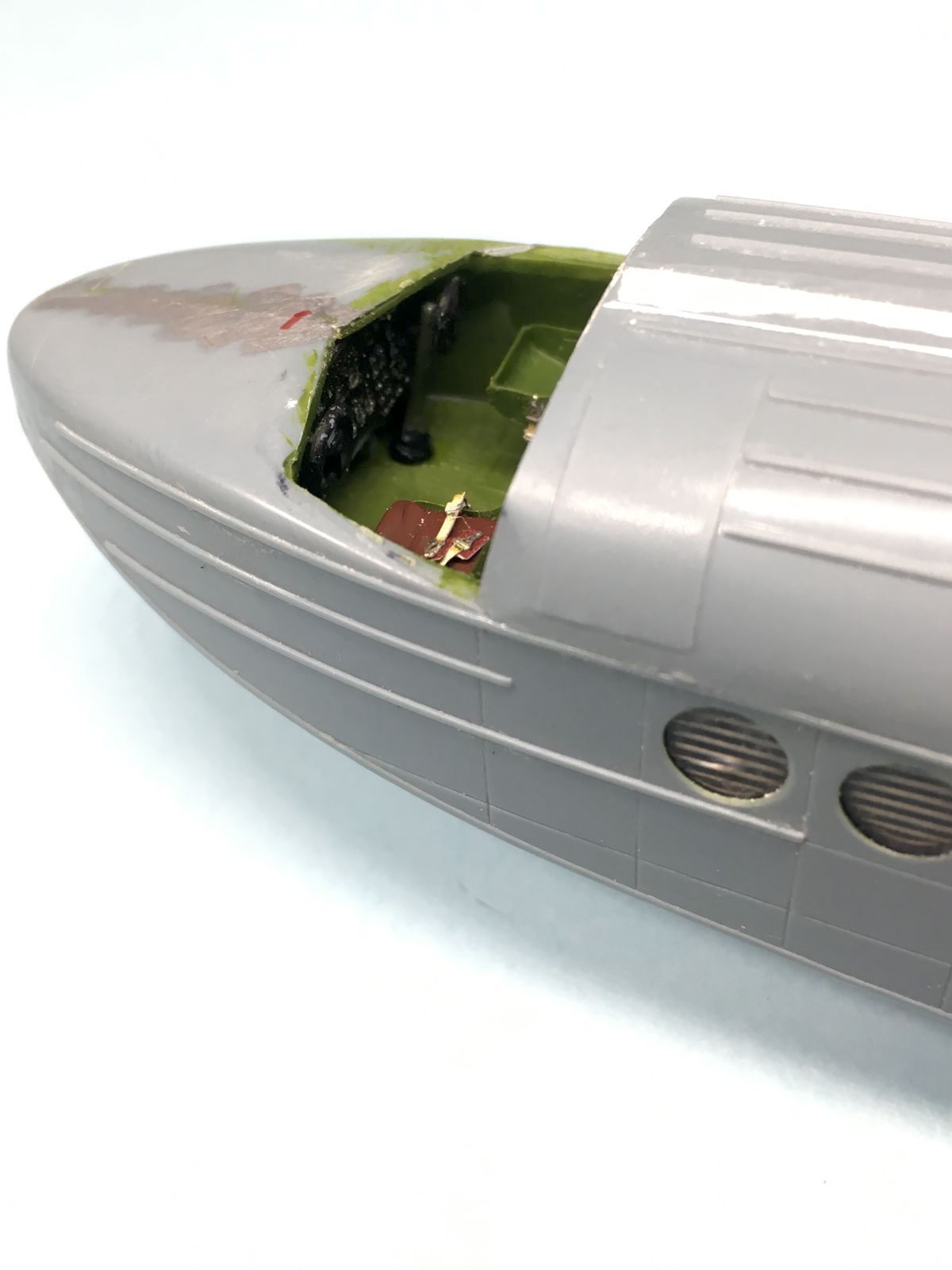
View into cockpit, harnesses as provided in kit
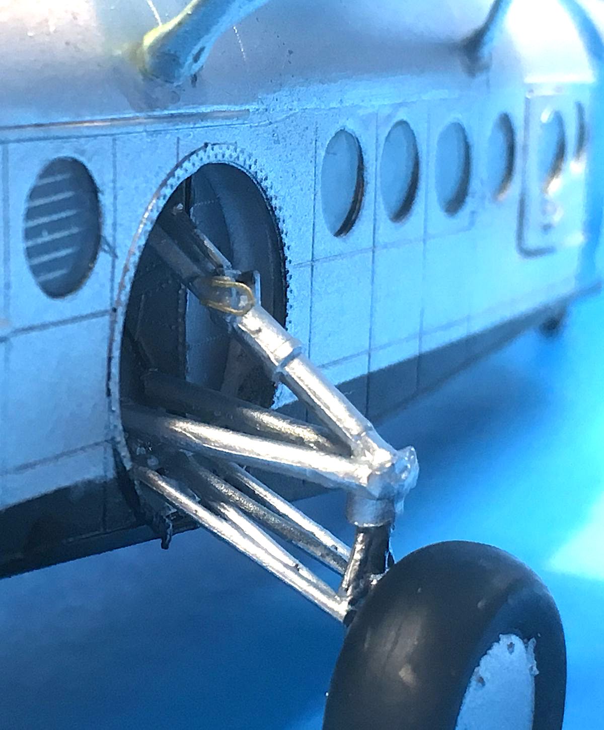
Modified gear struts, with examples of molding seams
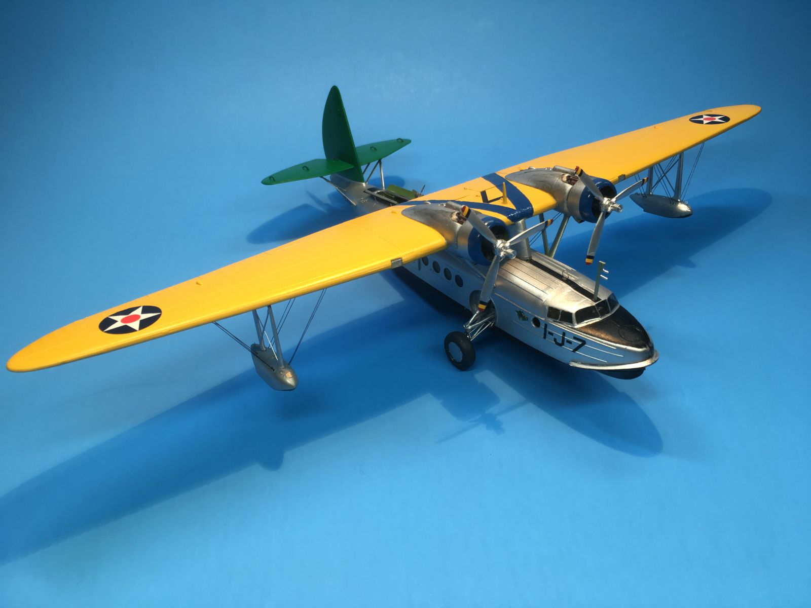
Completed model
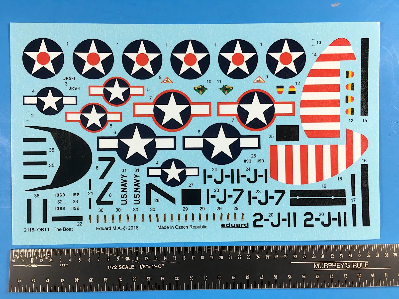
Eduard printed decal sheet, line of short decals at bottom are cabin seat belts
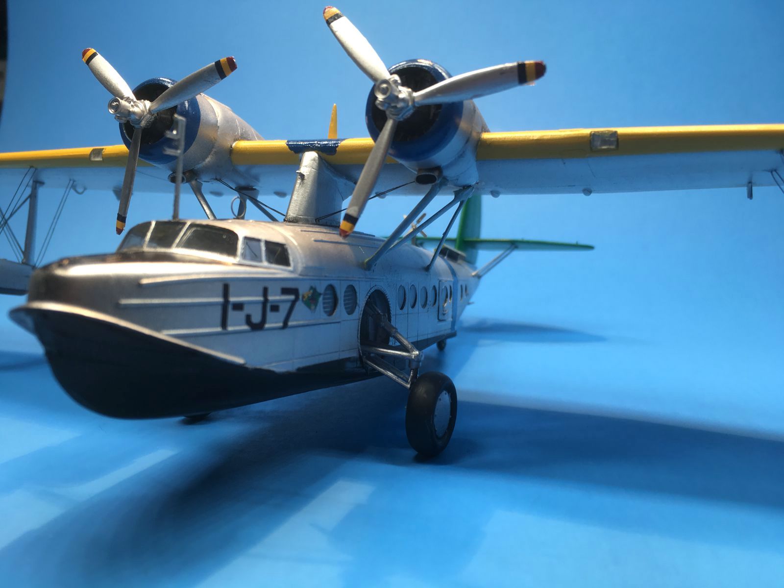
Completed model front view
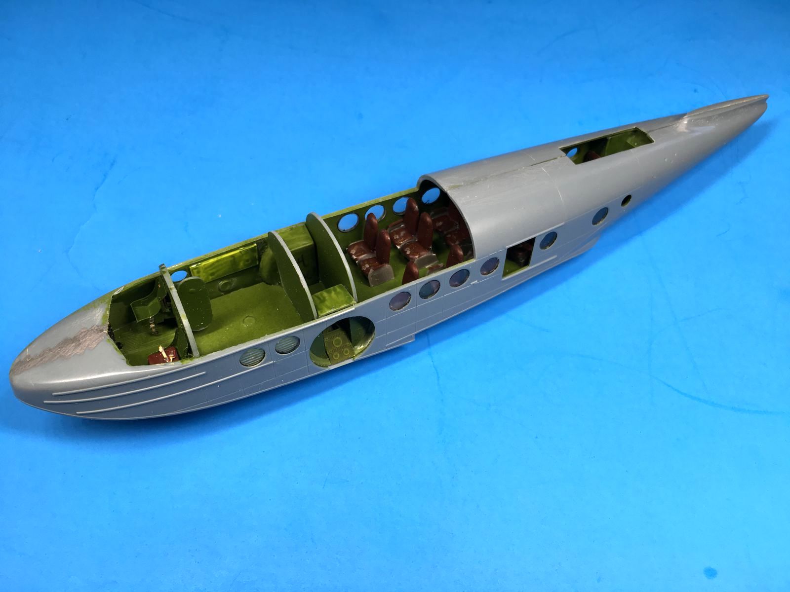
Port side fuselage in-progress, showing bulkheads
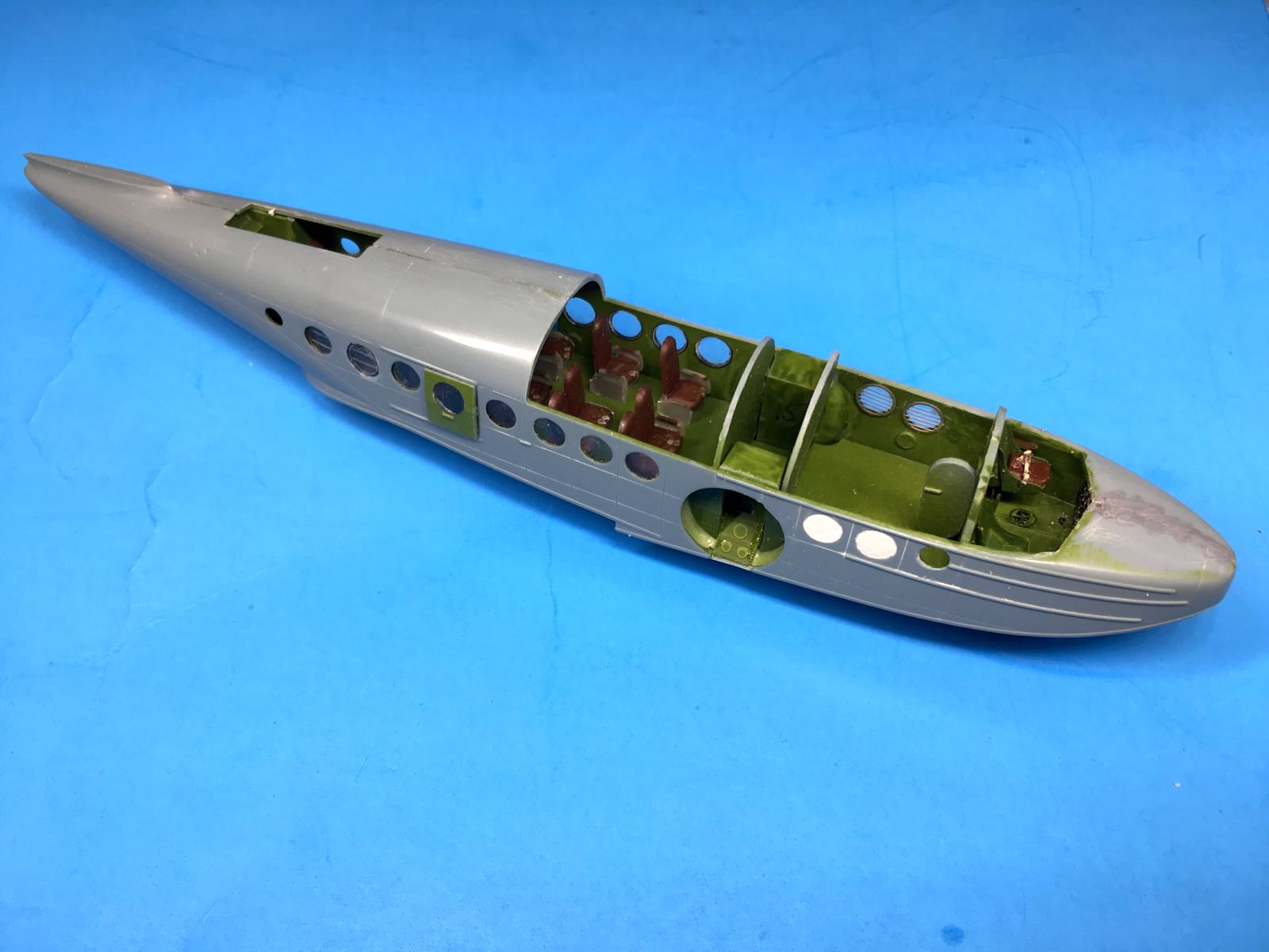
Starboard side fuselage in-progress, showing bulkheads and filled ports (in white)
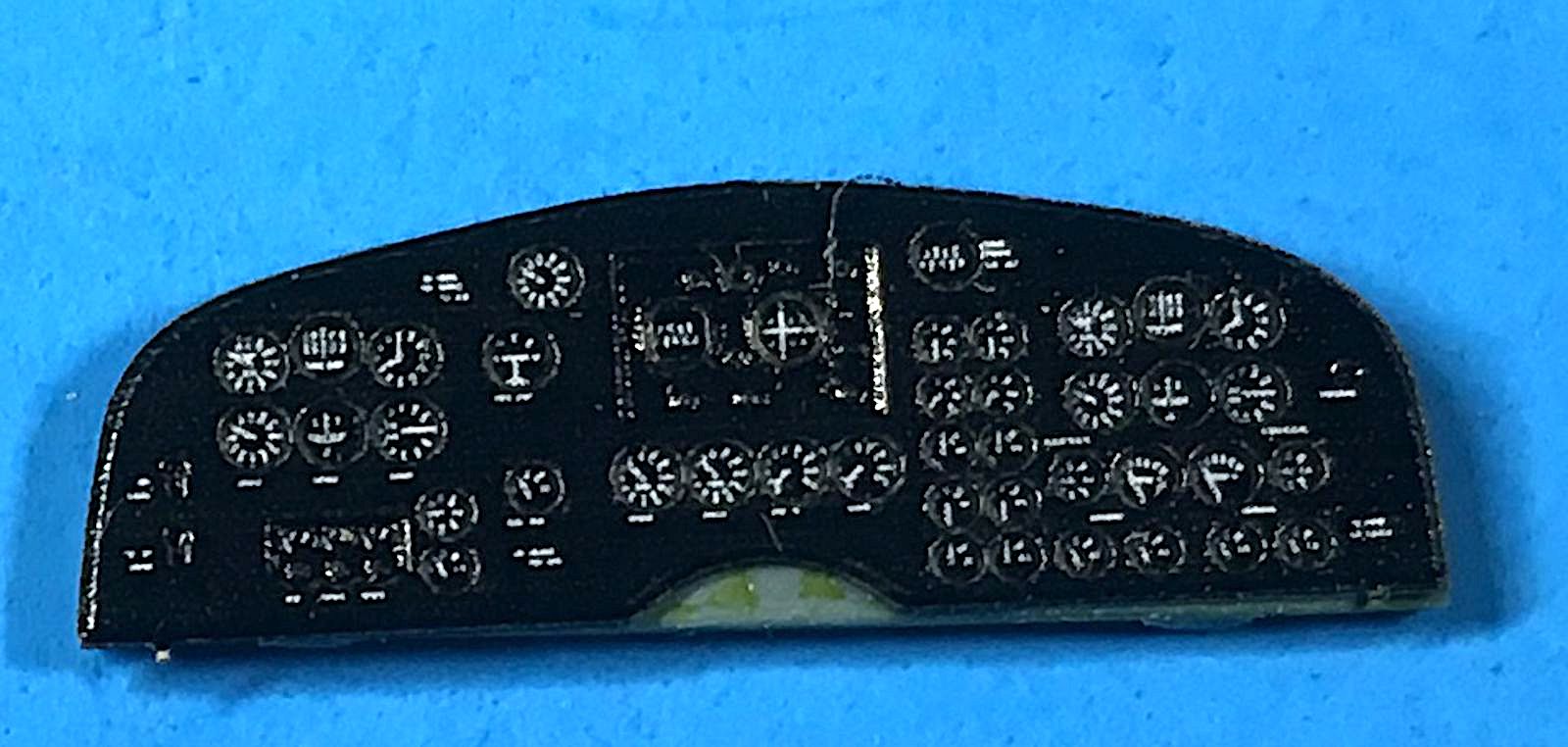
Assembled instrument panel color PE included in kit
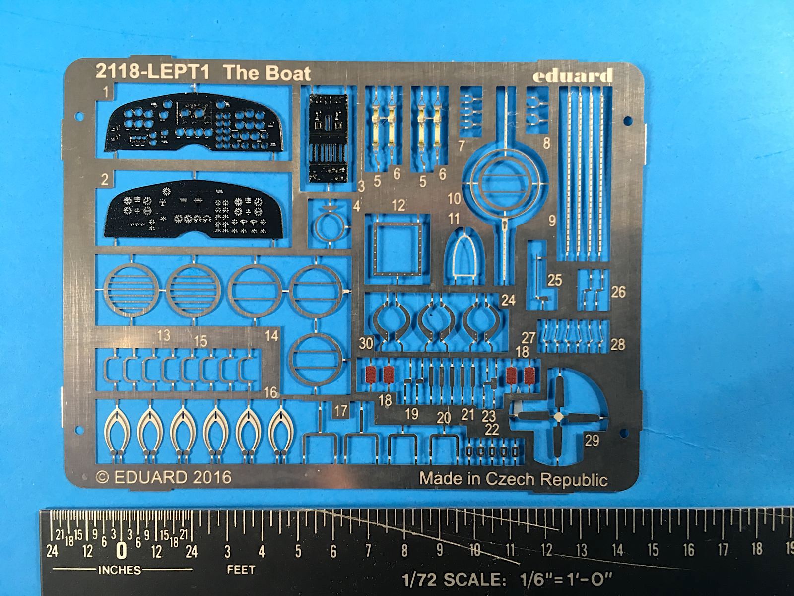
JRS-1 kit PE fret
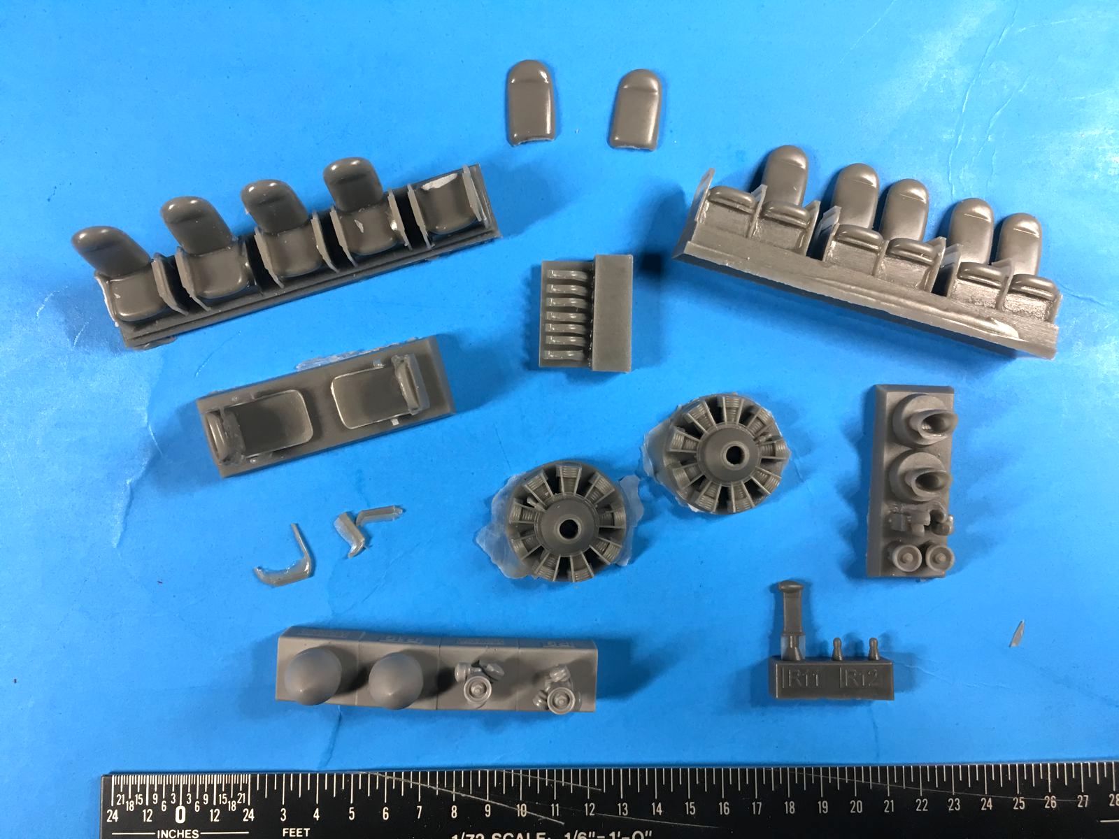
Resin parts on our plugs, note damaged seats
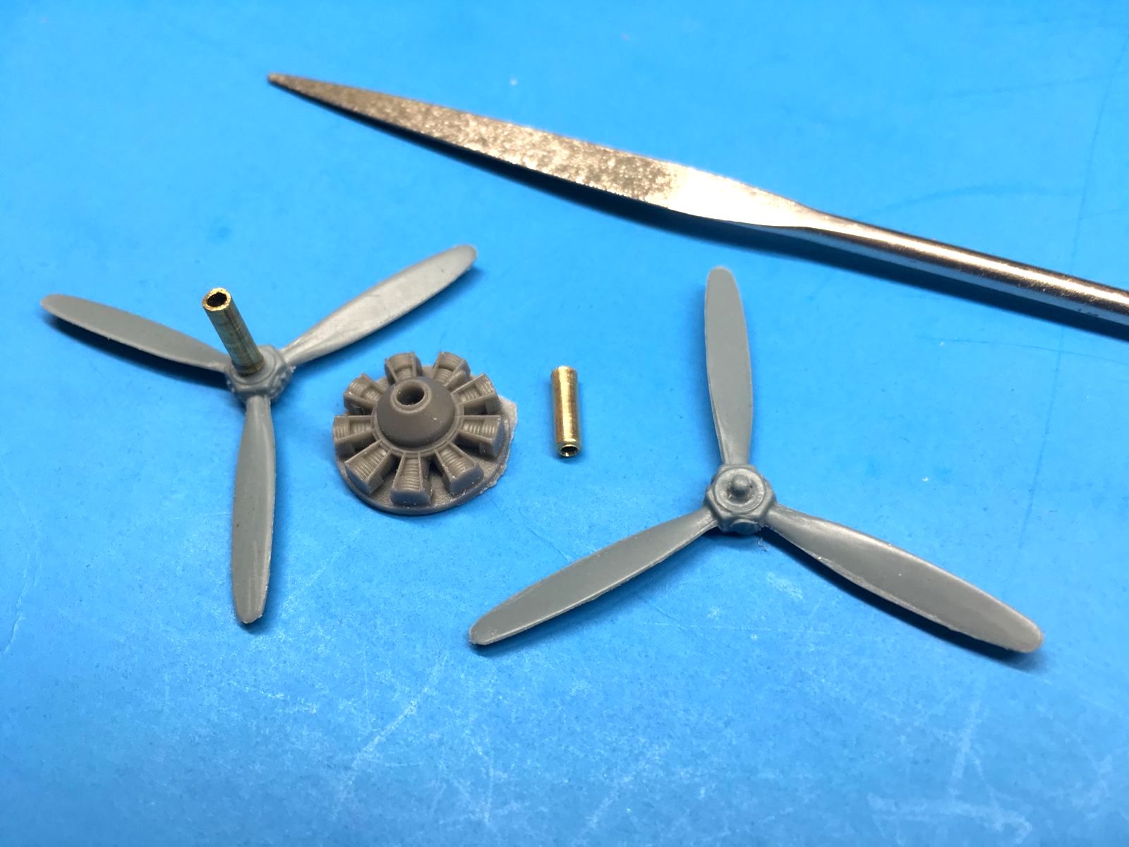
Kit props and engine, with added brass tubes to replace small original dimple-like kit shaft (on right)
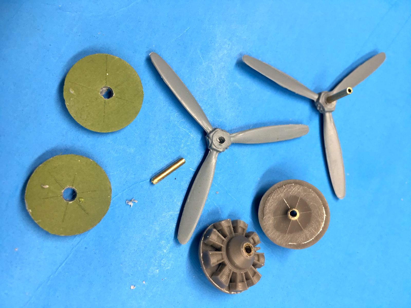
Modified kit props, engines, and drilled out bulkheads with added brass tubes
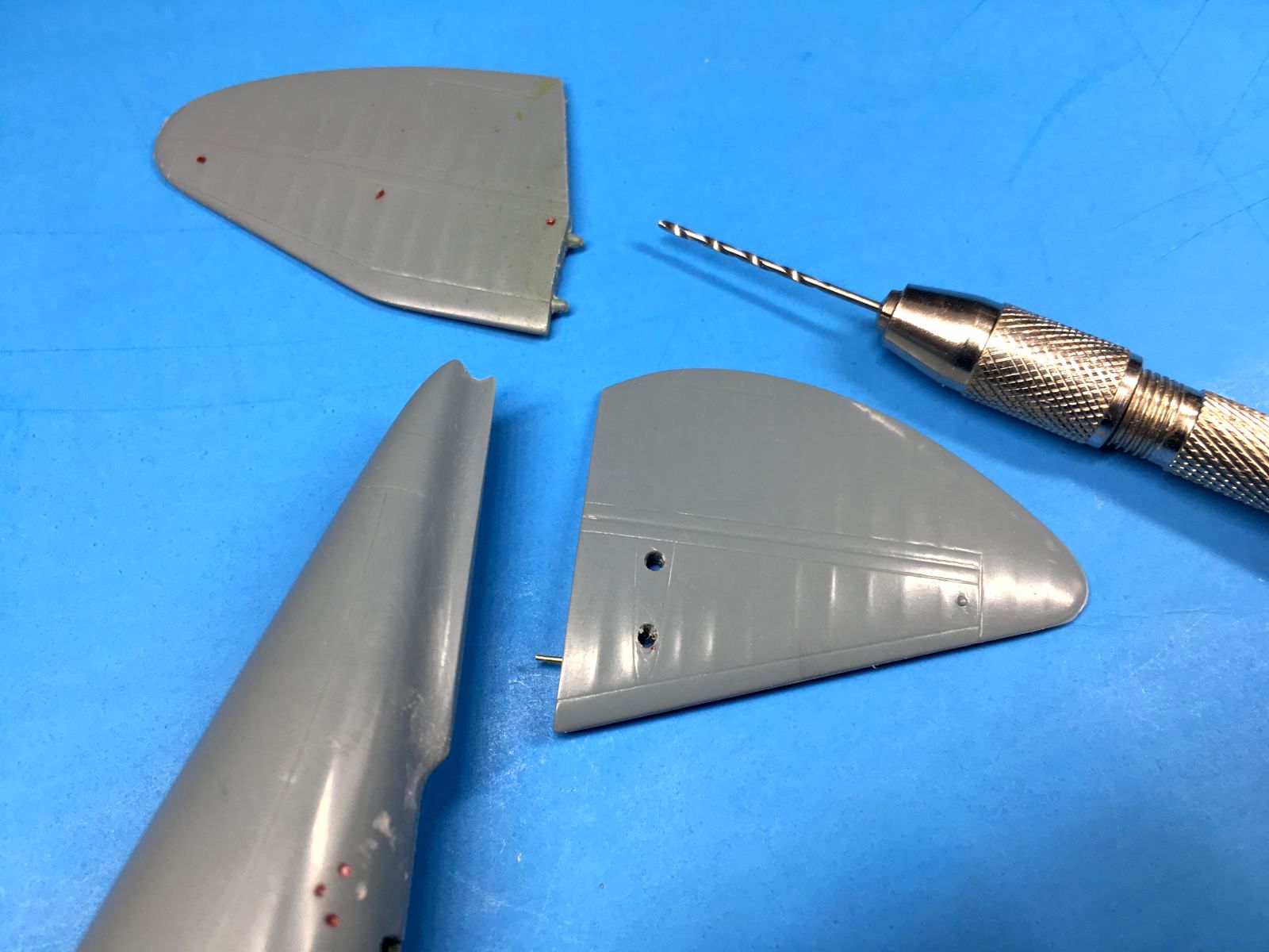
Tail surface modifications
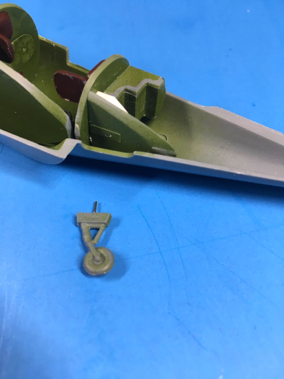
Tail wheel pin, note white plastic stock bulkhead brace above
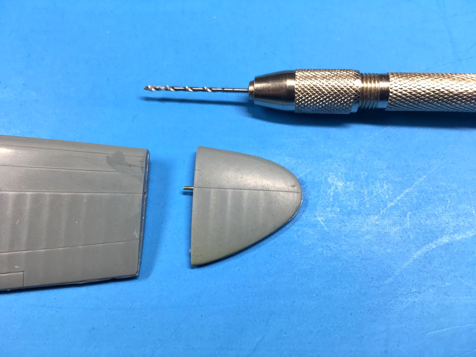
Wing tip brass pin reinforcement
Comments
Add new comment
This site is protected by reCAPTCHA and the Google Privacy Policy and Terms of Service apply.
Similar Reviews