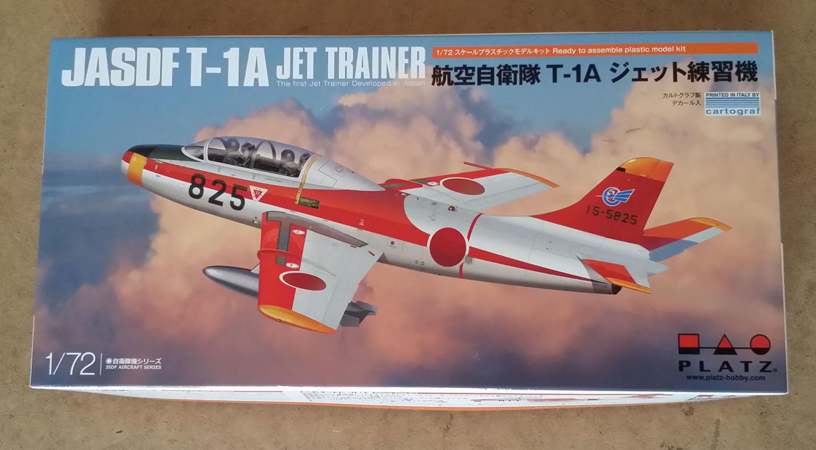
Japan Air Self Defense Force T-1A Trainer
The Fuji T-1A was the first Japanese-designed aircraft produced after World War II. Designed by Fuji Heavy Industries and powered by a Bristol Siddeley Orpheus turbojet engine, the prototype took to the air for the first time on January 1, 1958. 46 T-1As were built before the T-1B superseded it on the assembly line. They served as training aircraft until they were retired, with the final flight occurring on March 3, 2006.
This finely molded kit comes with 62 parts on three sprues, and two clear parts on a separate sprue. All the panel lines are engraved, and the fit is excellent. The kit comes with a photoetched (PE) painted fret for detailing the cockpit and the landing gear. While the instructions are in Japanese with only a descriptive paragraph in English, they are easy to follow.
Assembly began with the cockpit. There are numerous PE parts for detailing the interior. There are various places where the plastic parts have to be modified by removing details. The hardest one for me was removing the pedals from the cockpit tub, due to limited space. The ejection seats (Parts #B35) have 7 PE parts each. My recommendation for the order of assembly of these is #22, #19, #3, #18, #17, #25.
I installed several fishing weights into the nose to keep the model from sitting on its tail. There is some space on either side of the intake trunk in the nose, and some space on either side of the cockpit tub. The total weight I added comes to about 5 grams.
Numerous PE parts replace pieces of the landing gear and landing gear doors. I noted that the nose landing gear, part #B23, becomes extremely fragile at the piston above the wheel after having the scissors cut off. I reinforced that part of my nose landing gear with superglue.
There is one mistake on the instructions. In Step 4, where it shows the center divider for the main landing gear wheel wells, they call for Part #B6. In actuality, the part is #B9 on the sprue. The speed brake is replaced with a PE part that is a bit complex to assemble.
There is an option to have external tanks installed. Care needs to be taken to ensure the correct tank is glued to the correct wing, as the tanks are “handed”, and the sway braces fit to the outboard of the tanks. One other minor problem is the canopy extension ram, which the instructions do not clearly show where the ram fits on the canopy. I glued mine too far open, but that mistake allows you to see the cockpit much more clearly.
Decals are extensive on this model and offer a total of four options. All of the red and orange that is seen on my model in the pictures are decals. I worked from the nose to the tail and then the wings while decaling the model, going from the big decals to the finer detail decals. While there are dozens of small markings on the model, quite a few of them are grouped into single decals for application. The decals laid down snugly and responded well to decal setting solution. I spent a total of about 8 hours on the decals, spread out over the space of three days.
I spent a total of approximately 20 hours on this model. Both the PE parts and the decals took the majority of time.
My sincere thanks go out to Platz for providing my review sample.


Comments
Add new comment
This site is protected by reCAPTCHA and the Google Privacy Policy and Terms of Service apply.
Similar Reviews