
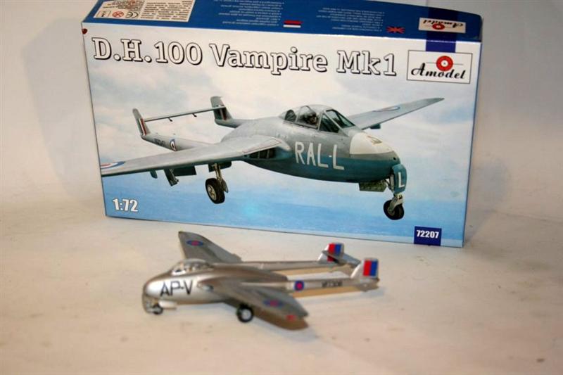
DH 100 Vampire Mk I
The Aircraft
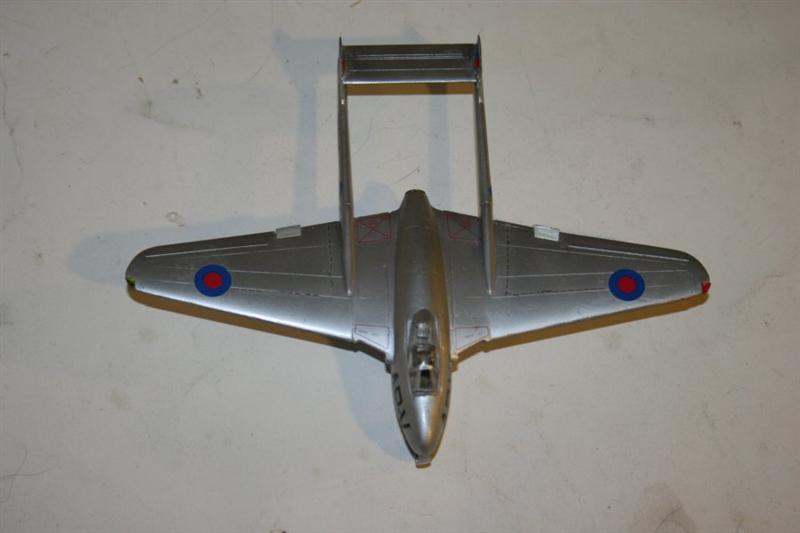
The Vampire certainly qualifies as an “early jet”, being second oldest to the Meteor in RAF service. The Vampire’s twin-boom layout was a result of the low power of the early jet engines. The shorter the tail pipe, the more power the engine could deliver. The Vampire’s original mission was strictly as an interceptor, with only the 4x 20 mm Hispano cannon as armament.
The Vampires had no power assist for the controls, no radar, and no vices. It was fondly referred to as the “aerial kiddie car” by post-war pilots, implying that anyone could fly it. This may explain why the Vampire was exported extensively. The export list includes: Austria, Australia, Burma, Ceylon, Canada, Chile, Congo, Dominican Republic, Egypt, Finland, France, India, Indonesia, Iraq, Ireland, Italy, Japan, Jordan, Katanga, Lebanon, Mexico, New Zealand, Norway, Portugal, Rhodesia, South Africa, Sweden, Switzerland, Syria, Venezuela and Zimbabwe. Vampires also served with the Royal Navy, and the first jet carrier landing and take off was a Vampire piloted by the famous Captain Eric Brown.
The Kit
When you open the box, you find the basics; 6 sprues of gray parts, one clear sprue with two canopies, the instructions and the decal sheet. AModel uses a low-pressure molding process, so the connections between the parts and the sprues have a larger diameter than most current kits. More on this later.
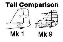
When I started this model, I had visions of doing an Egyptian Vampire to add to my “Suez Project”. But when I looked at the vertical tails, there was a definite difference, so I started research. I found my answer in Profile #48. “Mark Is, (with square-topped tail surfaces) entered R.A.F. service in 1946 as pure interceptors…” So the RAF markings in the kit are all you’ll need. The later versions with the triangular tails were the ones exported.
The instructions have a great feature. Next to the step number is a listing of all the parts you’ll need to complete that step. It’s really nice to know that you’re not going to find in step 7 that you left out a part in step 4 that can’t be added without tearing something apart. I give an “attaboy” to the instruction design team.
Construction follows a logical sequence; cockpit, jet pipe, nose gear, fuselage (including cockpit & jet pipe), tail booms, wings, combine major assemblies, and add landing gear, doors and detail parts.
Construction
What makes this a model for experienced modelers is the need for care and technique when assembling the fuselage “egg”. I ran into a fit problem with the fuselage when I first assembled it, as the cockpit floor seemed to be a bit too wide to allow the parts to mate correctly on the bottom. If I had followed my first thoughts and cut down the cockpit floor, I would have had really serious fit problems with the nose cone, the underside of the nose which contains the gun ports, and the fuselage belly which has the shell ejection ports.
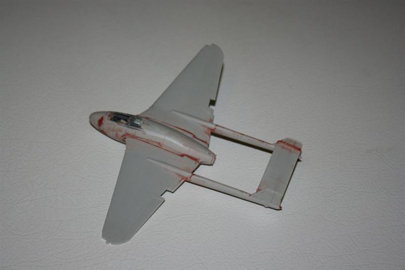
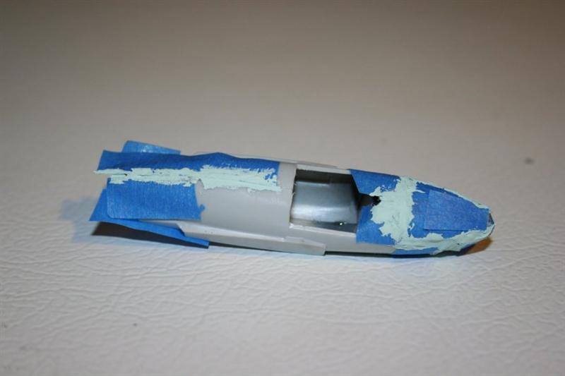
As it was, I felt like I was back to the 70s, using putty in copious amounts to get things to fit right. But when the whole thing was sanded down and cleaned up, the fuselage fit pretty well on top. The large gap on the bottom of the fuselage filled cleanly and looked OK after sanding.
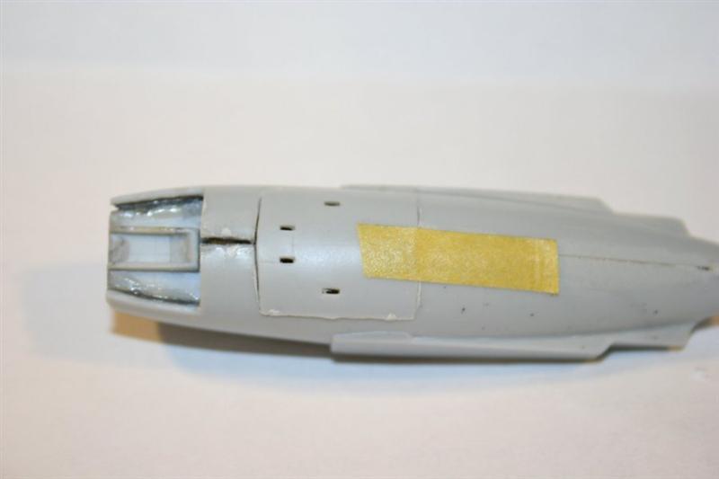
One of my problems was keeping the putty out of the gun ports while applying putty along the bottom of the fuselage and the nose cone. I used masking tape along the seams to keep the putty in its place, but these details were so close to the edge that I had difficulty getting the putty in the seam without going too far.
When I assembled the tail booms, I was pleased that AModel had made the vertical tails a single part attached to the outer half of the boom. This allows the leading and trailing edges to be nice and thin, without fooling around with a glue seam and gaps.
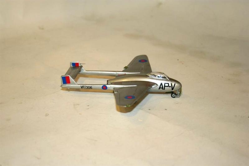
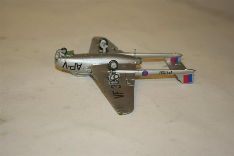
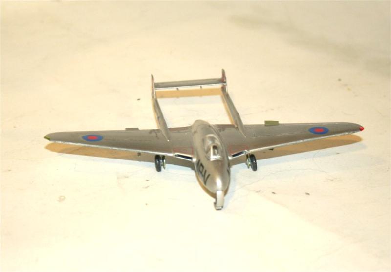
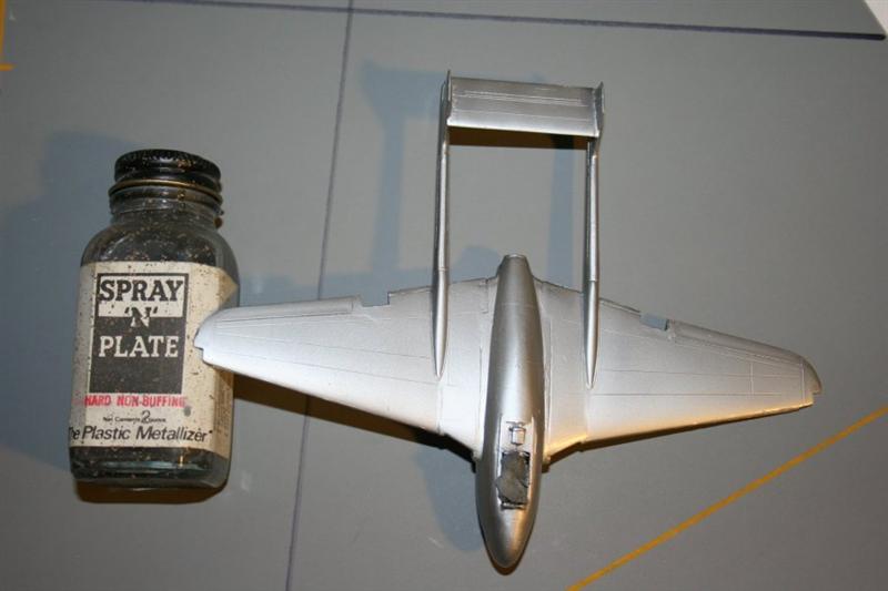
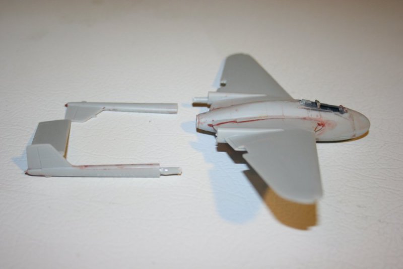
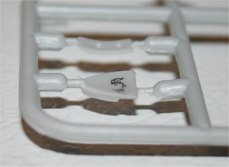
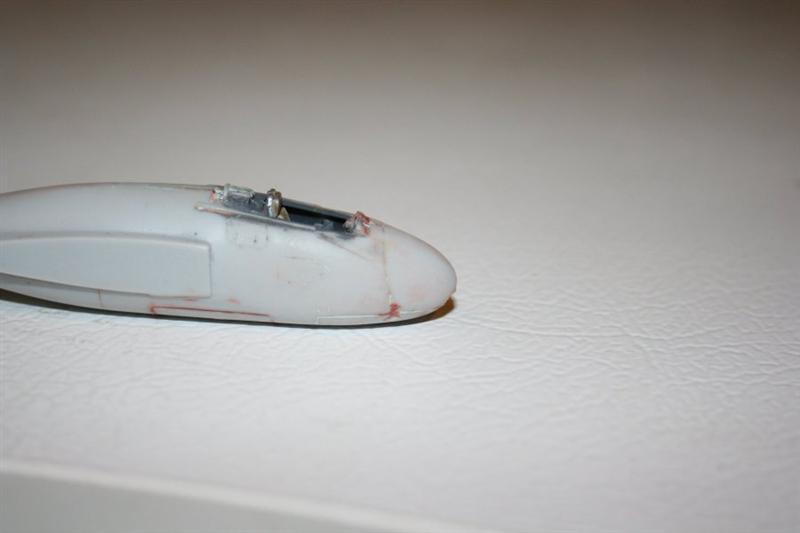
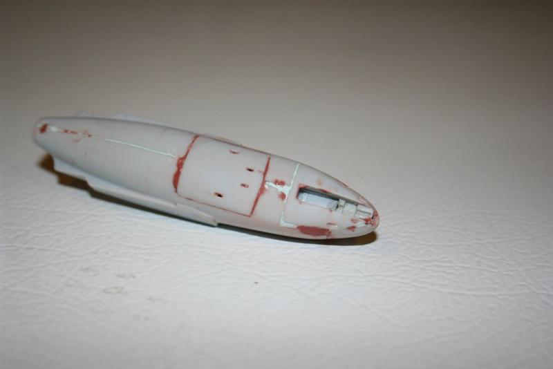
With the lessons of the fuselage firmly planted in my brain, I started the assembly of the wings. The wing assemblies are fairly simple, 3 parts, top, bottom and the intake duct. I was pretty suspicious of the duct, so I glued it to the bottom part, then test fit the top part. There was a definite gap between the leading edges of the top and bottom parts. And figuring that the cause was an oversized duct, I cut it down. And test fit again, with zero progress. If you look at the first photo, you’ll see a little “dimple” on the leading edge of the wing. This is where the sprue comes into the leading edge, and where I failed to completely clean up the sprue. It took about a minute with the sanding stick to fix this. My bad. The second photo shows how large the sprue-part connector is on one of the intake parts.
Once the wings were assembled and attached to the fuselage, it was time to attach the tail booms. Here again, modeling experience is more than helpful. The booms attach directly to the wing with no locators and no method for assuring correct alignment left/right, up/down or radially. I used a piece of sprue glued in the wing/boom connection to provide some stability and guidance. I used Testors Liquid Cement ® thickened with tube glue for this part, as I wanted the solvent from the liquid combined with the longer drying time of the tube glue to allow some working time to get the alignments right.
Painting
Once I had the joints for the wings and booms cleaned up, I proceeded with paint. I decided to do the silver Vampire. I found a bottle of Spray ‘N’ Plate, a pioneer in the metalizer realm, and used it. It worked fine. I gave it a chance to dry overnight, put on the coat of Future, and it was ready for…
Decals
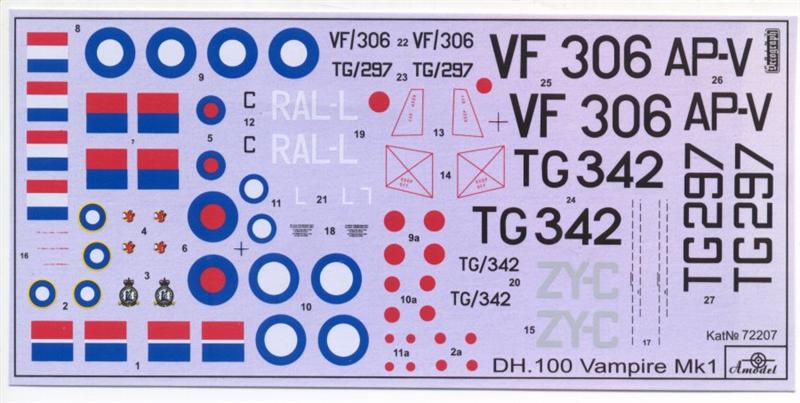
The decals are printed by Techograph, and they’re thin and opaque. My personal method for determining quality of decals is to see how long it takes for the decal to come free from the backing paper. Faster is better, and these were pretty good. I had a problem with the two dotted lines on each wing. These decals were so thin and fine that they broke apart while I was trying to align them. The only other spot that I wished for something different was the decals on the inside of the vertical stabilizers. The fin flashes go above and below the horizontal stabilizer on both fins. The decals come as two solid markings, and I had two problems. The first was cutting the decal perfectly square, and getting both exactly the same size. The second was that the decal needed to have a strip removed to make up for the thickness of the horizontal stab. Would it really have been that much trouble to make the decals two parts, each the correct size and shape?
Thanks to Paul Bradley for giving me the method for getting the underwing serial onto the gear doors.
A final coat of Future, and it’s on to the fiddly bits.
Final Assembly
The instructions come through again for the final assembly. The installation of the landing gear and doors is somewhat counter-intuitive, as the Vampire had the V-shaped parts on the shock absorbers on the front of the gear leg. Also, it was a big help figuring out where the main gear doors went.
There are two canopies provided, one for the silver aircraft, the other for the two camouflaged birds. The canopy fit quite nicely, is thin and very clear, and allows you to see that the Vampire did not have an ejection seat.
Overall Evaluation
Recommended. It’s a different variant from any other Vampire kit, so it’s a useful addition to your RAF display or collection. It’s also a kit for experienced modelers. Test fitting, filling, cutting and testing again are necessary to get through this project. There are issues, but nothing is a show stopper. The feeling of accomplishment is really there when you’ve finished this kit.

Comments
Add new comment
This site is protected by reCAPTCHA and the Google Privacy Policy and Terms of Service apply.
Similar Reviews