
Bf 109 G14/U4
Bottom Line Up Front
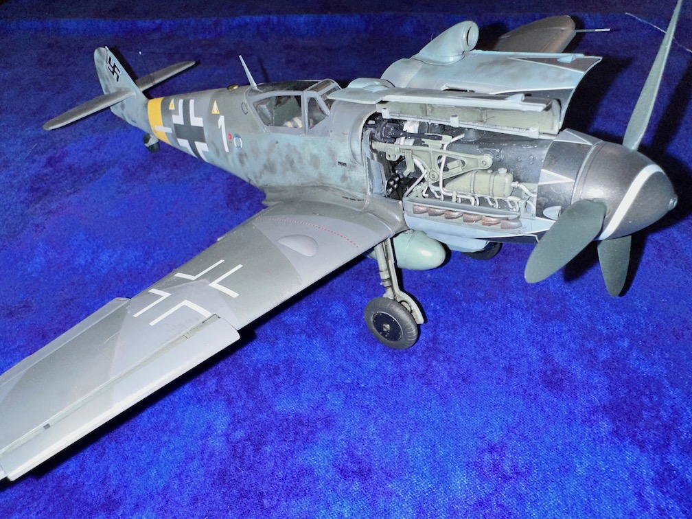
This is a new tooling of the Bf-109 G14 from Zoukei-Mura introduced in 2022. As with the two other Zoukei-Mura kits I have built (J2M3 and DO-335), this kit is really designed to have all of the panels opened. Especially those around the engine. With the panels opened up, you don’t need to worry about gaps and alignments. If you build the model with these panels closed, you will have to address the gaps, because they can be significant. If you want to build a 109 in this scale with the panels closed, you are better off with the Hasegawa kit. The Revell kit also has the ability to open up the engine bay and is less expensive. This kit is very detailed and you should take your time in building (or assembling) it. It builds up into a nicely detailed rendition of a 109.
I have one nit with it, and that is the fact that there is not a seatbelt included with the kit. For a kit of this size with the cockpit being a center piece, I believe that with little extra cost, Zoukei-Mura could include their seatbelts, which are sold separately. I tried purchasing them, but the Z-M online store did not have them in stock. Instead, I used Airscale 1/32 Scale Luftwaffe Seatbelts (SB32LFT). These belts are made of paper cloth and assembled easily and also were easy to install using PVC glue.
Paint call outs are shown throughout the instructions. Not all the parts need to be painted (for example, parts G-2 and G-3) because they will not be visible.
The decals by Cartagraph are great and settle quickly. Hartmann’s109 fuselage cross has an RLM 74 (graugrun) background and you need to mask off and lay the paint down exactly where the decal is to be placed, or if you feel lucky, mask the decal after placement and then paint. I chose the later without issue, after a solid top clear coat and time spent making the tape as unstick as possible.
The kit took about 150 hours to build (assemble?) from start to finish.
What’s in the Box
There are 14 sprues, including 2 clear sprues. It is obvious from the sprues that multiple versions of the G model 109 can be made from this kit, including early and late G6’s and other versions of G14’s. Both early and late canopy styles (early three part canopy) and the Erla canopy are present (both styles). Check your references if you choose to divert from the kit instructions and markings. The instructions are specific for a G14. The moldings themselves are a nice sturdy grey plastic and I have not noticed any odd deformations in any of the plastic parts to date. The clears are, well, clear with no deformations visible. Separating from the sprues proves to be no problem. Some seam cleanup is required, especially on the pipe fittings associated with the engine. As for sink marks, they are well placed and hidden from view. The only exception to this is on the right fuselage half interior (Sprue A) if you opt to have the access door open on the left fuselage half. And even then, you have to get light in there to see them.
There are two different instrument panels present, grey plastic and clear plastic. For the grey plastic you are given three approaches to completing the panel. Large decals containing multiple instruments, individual instruments, or hand painting the reliefs inside each instrument. For the clear panel, there are two approaches applying large decals on the back of the panel, or you can diverge from the instructions and place individual decals on the front or rear of the panel.
There is a nice rendition of a 35th scale figure of Hartmann included.
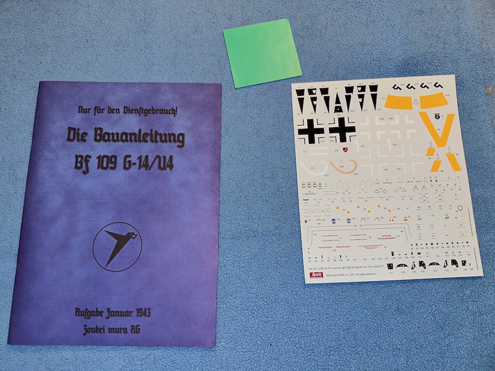
Instruction Manual, Paint/Markings Guide, Decal Sheet
ZM Instruction manuals are designed to look like an aircraft technical manual. The instruction manual is in two languages, Japanese and English. It opens up on page 3 with a brief history of the 109 including a brief overview of the engine and armament. The assembly information (pages 4-5) (See Figs 1-3) contains summarized information about the Bf109 G14 as well as a brief bio of Erich Hartmann. Color call outs (page 6) are straight forward using RLM numbers. The instructions utilize Vallejo and Mr. Color. Any brand of paint can be used with little effort. The meat of the instructions are broken down into five sections, Engine, Cockpit, Fuselage, Wings and Landing Gear, and Final Fitting. Each section highlights the parts required for that section, and include multiple pictures of the sub assembly or assembly. There are also exploded diagrams of various parts locations throughout. This helps a lot with parts placement. The painting guide in the instructions is in color which makes for an easy-to-use reference.
Assembly
Engine (Section 3-1 of Instructions)
The left and right cylinder banks (part #’s E2 to E5) can easily be misaligned (Fig 4). There are no firm male/female alignment locations. Pay attention to make sure they are aligned properly. The seems associated with these parts is easily blended with a little sanding.
Parts E-48 can easily be glued into place. Take care or you will have a non-rotating propellor. Don’t ask how I know.
There are options along the way for the lower panel to build open or closed. I chose the closed option.
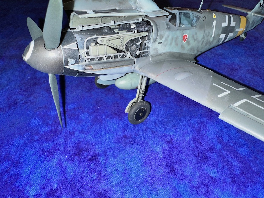
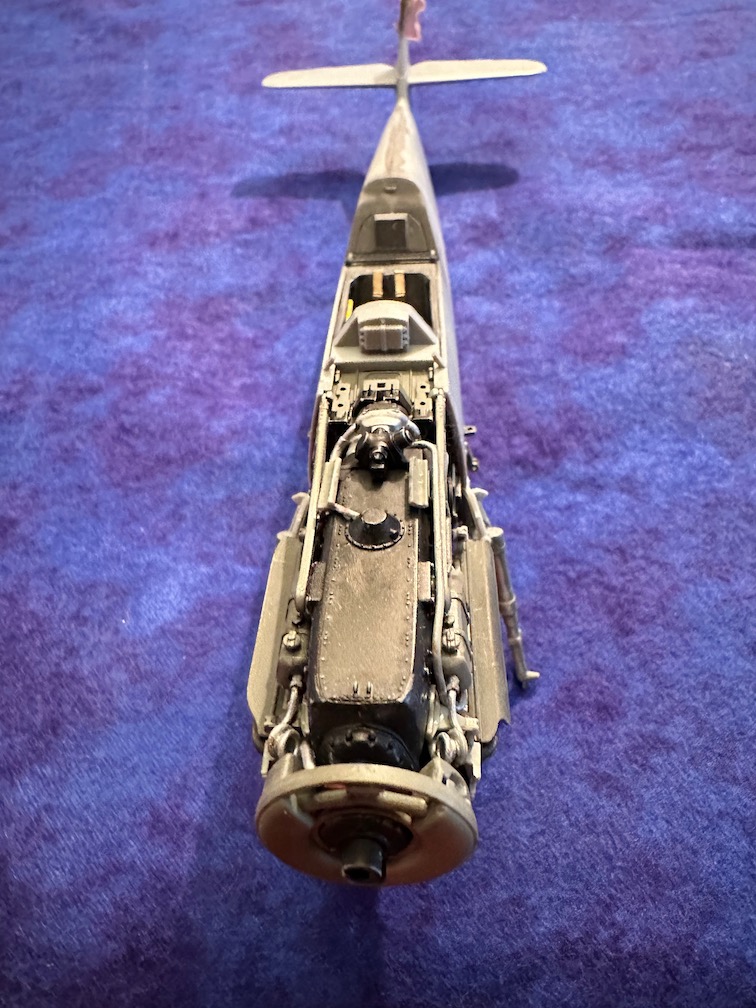
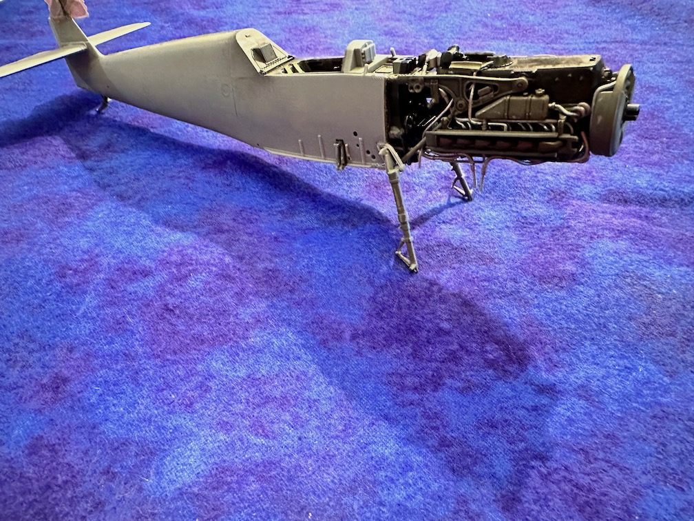
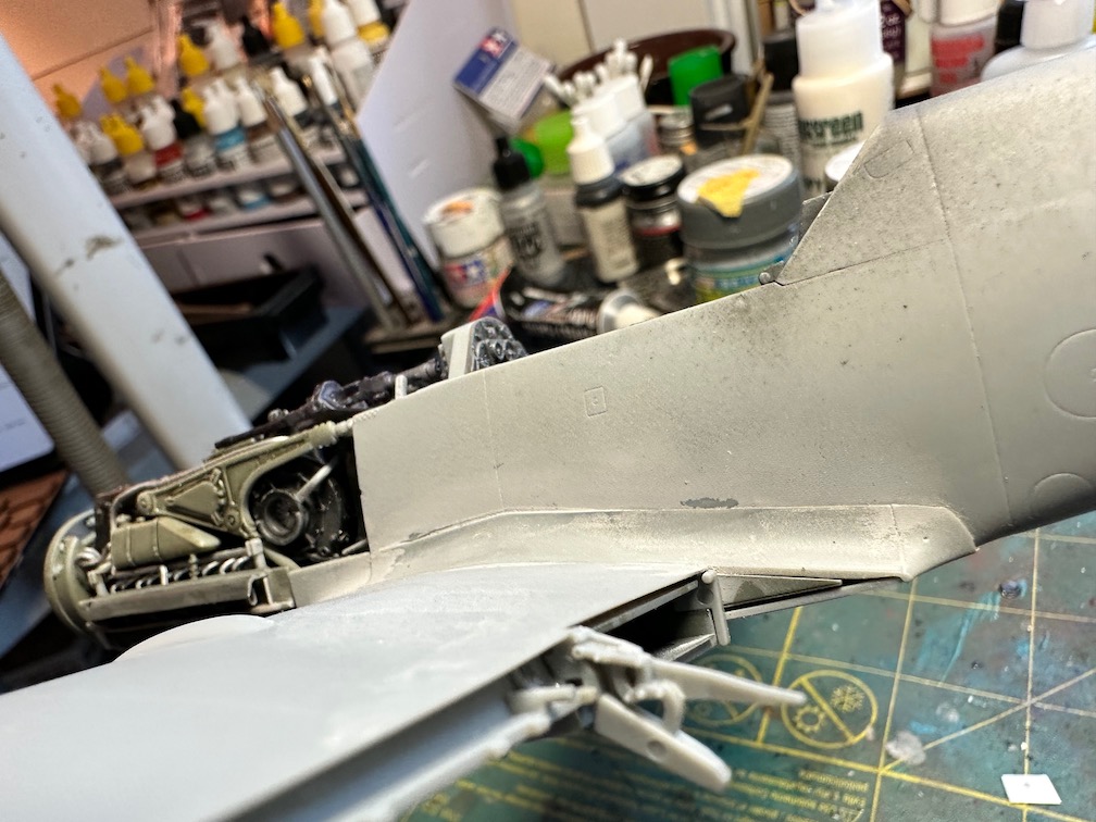
Otherwise, the engine assembly is fairly straightforward and builds into a nice rendition of a Daimler Benz DB 605 AM engine.
There is the option of building an engine stand so that you can display the engine outside of the aircraft. If you go this route, be aware that you will have some gaps to address in all of the engine panels. See figures 5, 6 and 7.
Cockpit (Section 3-2 of Instructions)
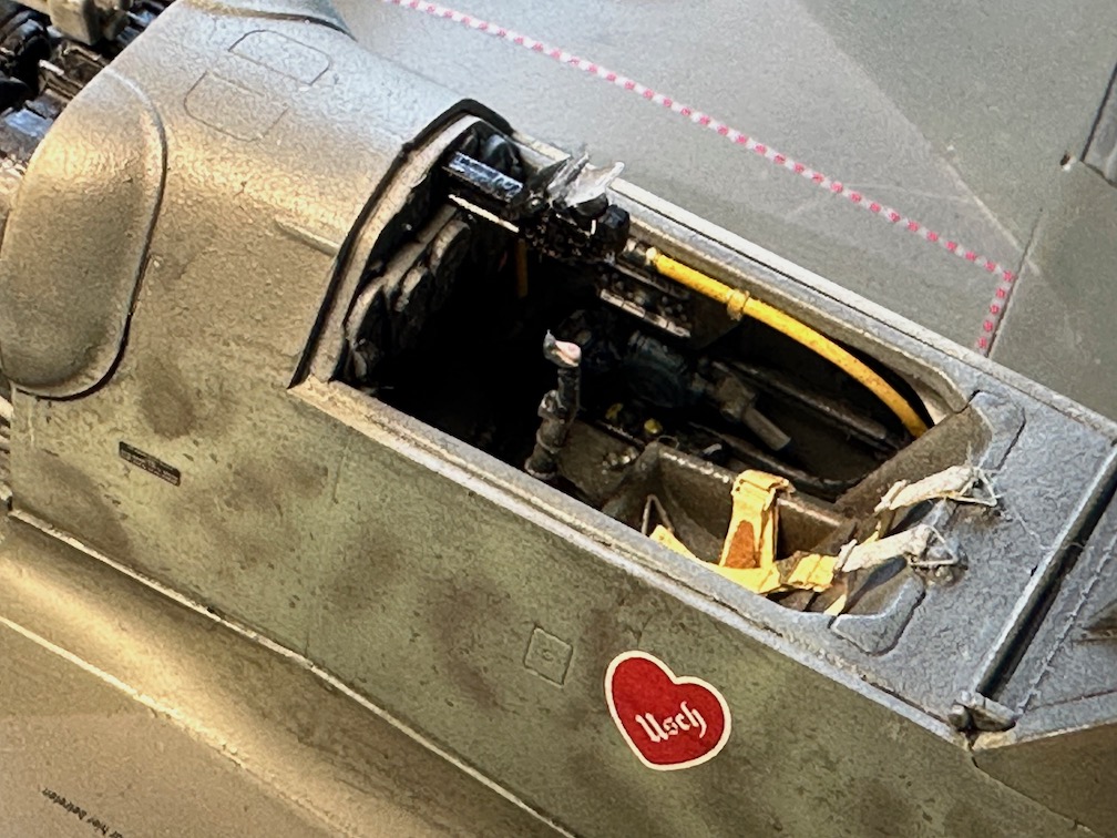
The cockpit assembly is straight forward. Take your time and follow the instructions and the cockpit will show off nicely.
This is the first 109 cockpit I have built that actually includes a control stick/surface lock (part G33 - Fig. 8). So, I varied from the instructions and actually locked the stick into neutral position. Make sure that the control surfaces match the stick position.
There are two options to build up the instrument panel (Fig. 9), a sold piece (gray) IP, and a second option with a clear IP. As for the instrument decals themselves, there are three options, individual instruments, one solid decal for the entire panel, and a third option with segmented instruments for the IP. With the clear panel, you can place the decals on the rear of the clear IP. I chose the gray IP with individual instrument decals. Fig 9a)
Pay close attention in step 3-2L. This step installs the landing gear side brackets (structural gear support). If not installed correctly, the gear will end up cattywampus and there is also potential to throw the engine bulkhead alignment off when installed into the fuselage. Fig. 9b shows the competed cockpit.
Also, take care in step 3-2M. This step installs the fuselage fuel tank (Fig. 10). If not installed correctly, it can cause issues when you install part A-36 (lower wing center section). If A-36 is off, your wing alignment will be off.
Fuselage (Section 3-3 of Instructions)
Kudos for Z-M to tell you to actually dry fit the fuselage assembly (Fig. 11). This is probably the most important step of the instructions. There are a lot of fuselage frames and the cockpit framing to worry about in this section (Fig 12). Here is where the fit of the gear, the engine mounts, and wings all comes together and can easily go astray. Make sure the front cockpit bulkhead is evenly aligned with the front of the fuselage halves. If not, the engine mounts will be out of alignment. Also, pay attention to the side brackets installed in step 3-2L. They should align and be flush with the cut out designed for their installation on the fuselage halves (Figs. 13, 14, and 15).
If you want to have the fuselage compartment opened (by not installing part A-5), you should eliminate the sink marks on the right side of the fuselage (Fig 11a). These are easy to blend out. With the fuselage opened up, there is not much light that gets in to illuminate the structure and equipment installed. In fact, the avionics equipment as well as the fuel tank are very difficult to see. The only really visible item is the IFF (part A-12) and the Master Compass (Part F-3). I ultimately decided to leave the access panel (part A-5) installed because of the lack of lighting for the interior.
With the fuselage together (Step 3-3E), it is a good idea at this point to dry fit the lower center wing section (Parts A-36 and I-6 - installed in section 3-4) to make sure you have a flush alignment with the lower center wing center section and the fuselage.
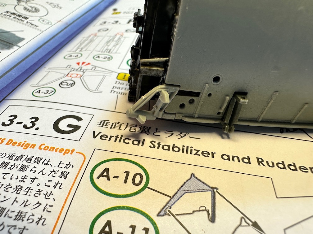
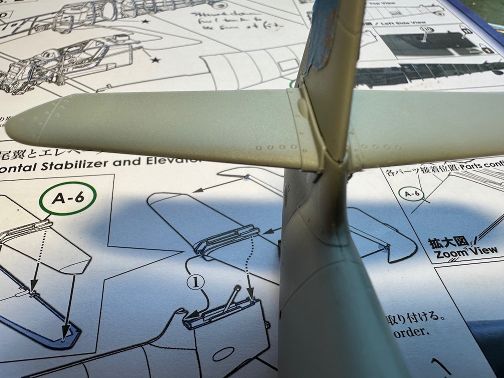
Steps 3-3F and 3-3G deserve a special call out. The tail structure of the 109 was significantly changed between the E and F/G models. The E and earlier models had lower braces supporting the horizontal tail. Starting with the F model, the structure on the roots of the horizontal tail were beefed up. This structure is accurately represented on the Z-M kit. There will be a step slightly above the horizontal tail surface on the vertical tail. This is supposed to be there! This change beefed up the tail structure and reduced the overall drag of the aircraft. The reason I point this out is that I encountered an online build of this kit where the builder spread out the vertical tail to make the entire vertical tail surface flush. Do not do this! (Figs. 16 and 17)
With everything aligned (Fig. 18,18a, and 18b), installation of the main gear should be issue free. Be sure to clean up the seams on the gear first. Likewise, the engine installation should be issue free if the alignment is true. I also described the fuselage seam lines that are present on the 109 (Fig 18c).
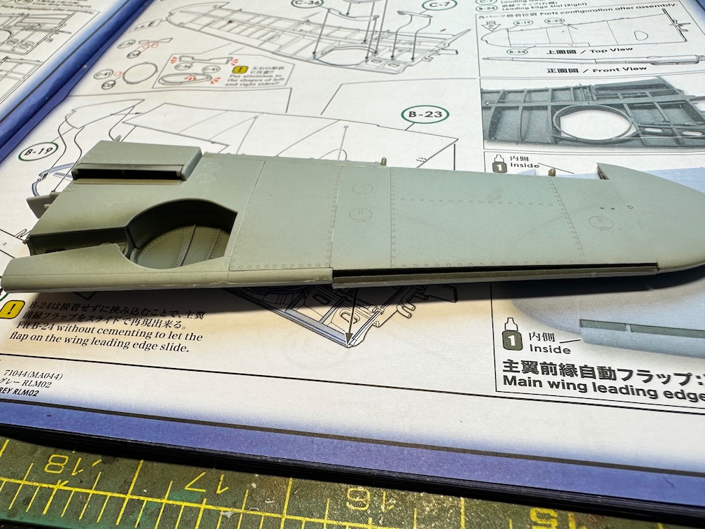
Wings and Gear (Section 3-4 of the Instructions)
As with the rest of the kit, take your time and dry fit, dry fit, dry fit. The build up of the interior wings is fairly straightforward. Just make sure that you correctly follow the plumbing routes of the various piping.
The left and right radiator ducting at first seems a bit confusing, especially the radiator actuator attachments (part C-5 for both wings). Instead of following the directions (up from the bottom to the attach point), I found it easier to go from the top down. It was easier for me to attach the actuator at both ends as a result. (Fig. 19)
Care should also be taken on the gear well side walls (parts C-35 and C-36). Make sure they are flush with the structure top and bottom in order to ensure proper wing panel fit.
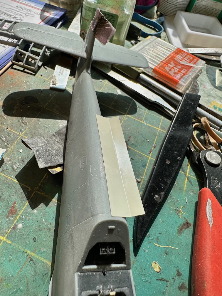
Dry fitting is very important when it comes to attaching the wing panels. If all goes well, everything from wing tip to wing root, top and bottom, will be flush with no gaps. It is very easy to get the wingtips (parts B-19, B-20, B-21, and B-22) to not sit flush with the inboard wing panels. I sanded down the interior structure just a bit so that the wing tips were flush. (Fig. 20)
The wing center section, when assembled, (part I-6 with A-46) can be prone to a step between the two parts. These parts do not have a positive join, but are akin to gluing two flat plates together. To alleviate this, I used some evergreen sheeting as a mount for part I-6 to alleviate this potential. (Fig. 21 and 22)
Step 3-4O is really a decision tree for having the engine cowling panels opened or closed. Choose wisely.
Attaching the wing fillet was also straightforward, however there was a bit of a gap on the front part of the right fillet (part A-8, Fig 23) after installation when compared to the left. Go figure. I used Mr. Surfacer to address this.
The upper engine cowlings, if you opt to have them open, have a number of sink marks that need to be addressed prior to installation (Fig. 24). Attaching the cowlings to the engine cowl hinge (part H-8) proved to be a hunt and peck method of attaching the parts. There is no clear attachment point. However, after multiple attempts at trying to figure out where and how they attach, and using the figure shown in Step 3-4V (Fig24a). I settled on a location that looked right to me. I opted to have the lower cowling closed. And yes, there is a gap between the rear of the cowling and the lower wing center section. I opted not to address this gap. If need be, the lower cowling fits snugly without glue, and can be removed.
Final Outfitting (Section 3-5 of Instructions)
This section starts out with attaching the radiator flaps (upper and lower) and outboard of those, normal flaps. There are multiple configuration choices for the radiator flaps: both closed, lower flaps down, and both flaps down. But, before you get started with the fiddly bits (flap attachments - parts C2, C4, C10, C12, and C17 through C24) there may be some gaps that need to be addressed if you want the flaps down. The gaps, if present, are located on the fuselage itself, between the wing fillet, the cockpit insert, and the lower wing center section. In essence where the flaps but up against the fuselage when both flaps are closed (Fig 25). These gaps are noticeable if any of the flaps are in the down position. I used Mr. Surfacer to fill them. And then painted them RLM 66. The flap actuators/hinges and flaps themselves install easily. I had to sand the flap actuators once attached to the radiator flaps to ensure they were flush with the flap itself. More likely my doing than an issue with the kit.
The rest of the section is straight forward and there are no real issues with assembly from this point on. Personally, I didn’t like the way the open canopy was attached to the right canopy sill. It just didn’t look right to me, so I opted to have the canopy “removable” to show off the interior. The clears are well, very clear, and cockpit detail is visible even with the canopy closed. The only other recommendation is to install the left and right Nav light clears (parts O-4 and O-5) prior to paint and get them flush with the wing tips. I opted to do attach them after I painted the wings.
I opted to install the gunsight at this time. The gunsight sprue attachment was in a very awkward location (Fig. 26) that casques a lot of part clean up for a clear part. Finally installed after a lot of effort (Fig. 27).
Painting and Decals
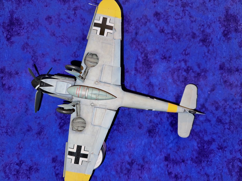
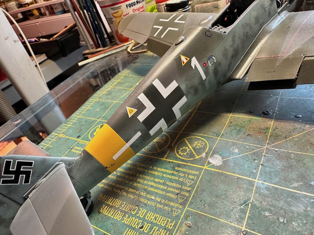
You get two options with this kit, Erich Hartmann’s or Anton Kellmayer, who flew this aircraft after Hartmann. The paint schemes are the same, and Kellmayer’s markings include some additional Yellow ID bands on the port wing. I painted the aircraft using Testor’s Model Master enamels with no issue. The paint masks are great and you get both interior and exterior tasing so you can easily paint the internal framing. As mentioned earlier, the fuselage crosses are clear, so you need to paint RLM 74 under (or over) the decal to properly display the fuselage cross’s (Fig 28). One other point on the decal instructions, decal A4 should be decal A14, and decal A12, should be decal A2. I did have difficulty with the spiral decal on the spinner. My own ham handedness contributed significantly to its misapplication. I opted to paint the spiral on. See Figs. 29-32 for the completed kit.
Overall, a great kit that was fun to build.
Thanks to IPMS/USA and Zoukei Mura for allowing me to review this kit.

1
2

3
4
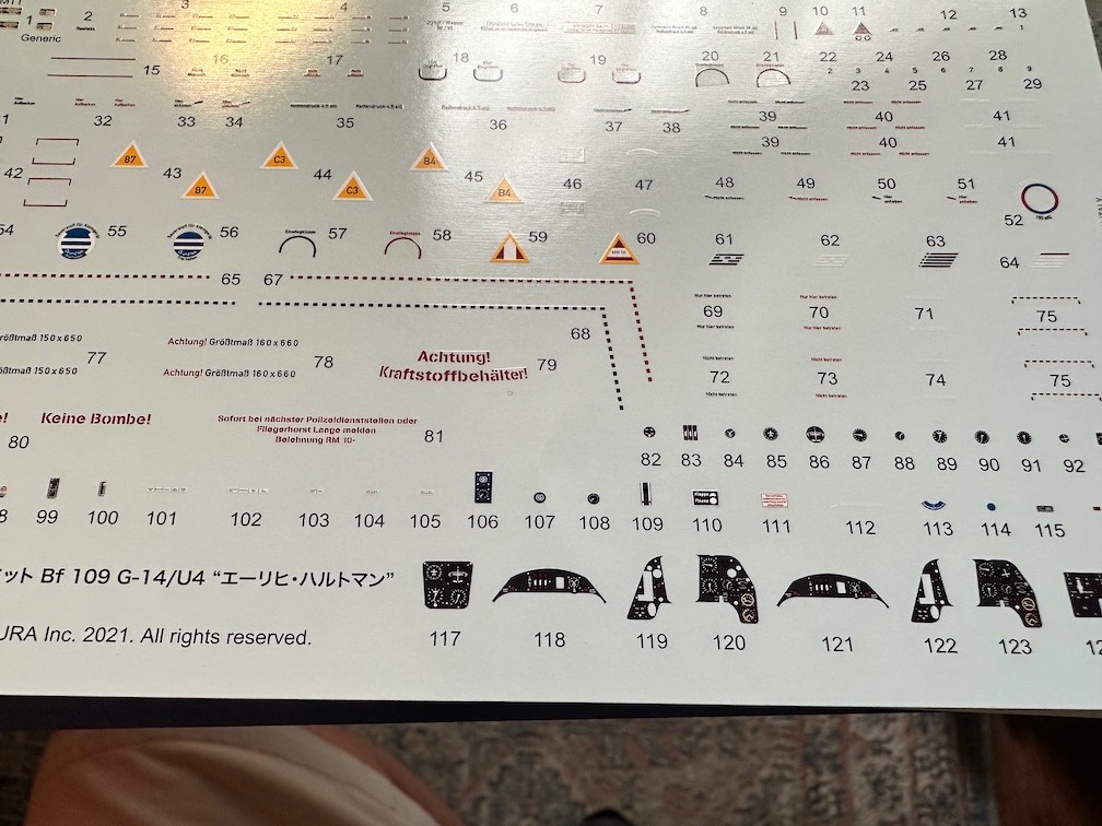
Inst manual, decals, and masks

canopy masks
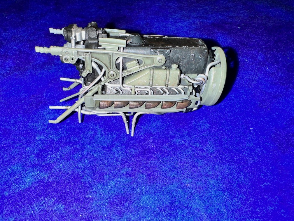
completed engine
Instrument Decals
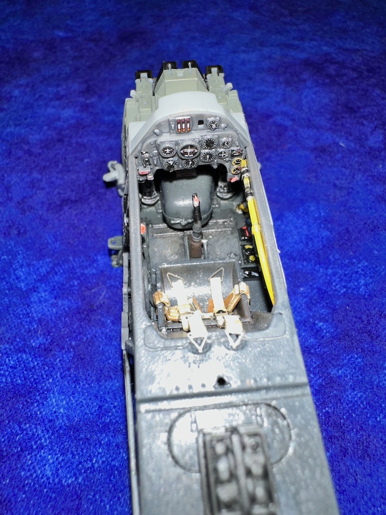
Completed cockpit
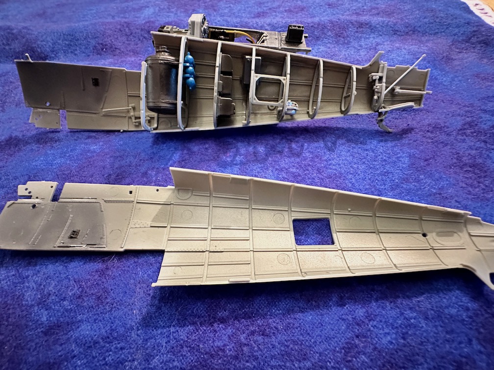
Completed fuselage interior
Fill those gaps
Vertical tail installation
Checking fuselage alignmnet
Fuselage all upright
Scribing the infamous fuselage line
Starboard wing assembly
Gaps near flaps
Gun sight installed
Comments
Add new comment
This site is protected by reCAPTCHA and the Google Privacy Policy and Terms of Service apply.
Similar Reviews