
A6M2b Zero Model 21
Brief History-Wikipedia
The Mitsubishi A6M "Zero" is a long-range carrier-based fighter aircraft formerly manufactured by Mitsubishi Aircraft Company, a part of Mitsubishi Heavy Industries, and was operated by the Imperial Japanese Navy from 1940 to 1945. The A6M was designated as the Mitsubishi Navy Type 0 carrier fighter, or the Mitsubishi A6M Rei-sen. The A6M was usually referred to by its pilots as the Reisen, "0" being the last digit of the imperial year 2600 (1940) when it entered service with the Imperial Navy. The official Allied reporting name was "Zeke", although the name "Zero" (from Type 0) was used colloquially as well.
The Zero is considered to have been the most capable carrier-based fighter in the world when it was introduced early in World War II, combining excellent maneuverability and very long range.[2] The Imperial Japanese Navy Air Service (IJNAS) also frequently used it as a land-based fighter.
In early combat operations, the Zero gained a reputation as a dogfighter, achieving an outstanding kill ratio of 12 to 1, but by mid-1942 a combination of new tactics and the introduction of better equipment enabled Allied pilots to engage the Zero on generally equal terms. By 1943, the Zero was less effective against newer Allied fighters due to design limitations. It lacked hydraulic boosting for its ailerons and rudder, rendering it extremely difficult to maneuver at high speeds. By 1944, with Allied fighters approaching the A6M levels of maneuverability and consistently exceeding its firepower, armor, and speed, the A6M had largely become outdated as a fighter aircraft. However, as design delays and production difficulties hampered the introduction of newer Japanese aircraft models, the Zero continued to serve in a front-line role until the end of the war in the Pacific. During the final phases, it was also adapted for use in kamikaze operations. Japan produced more Zeros than any other model of combat aircraft during the war.
The Kit Contents
Plastic Parts
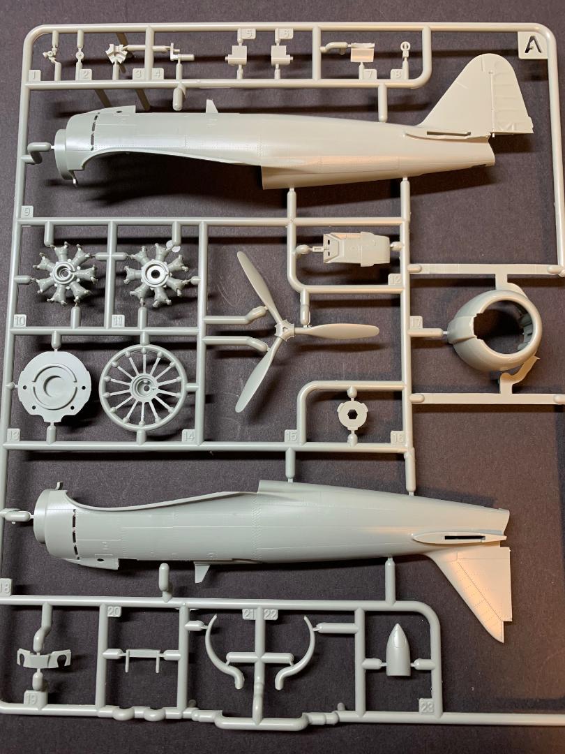
There are five light grey plastic trees for the kit parts. The parts are generally bagged two trees per bag. Parts not to be used are noted in the lower right hand corner. Looks like another Academy Zero may be in the works (??).
Clear Parts
There is a single clear parts tree with four parts, offering the builder the option to model the aircraft with the canopy open or closed
Photoetch
None provided.
Decals
A small sheet of decals is included with marking for several aircraft.
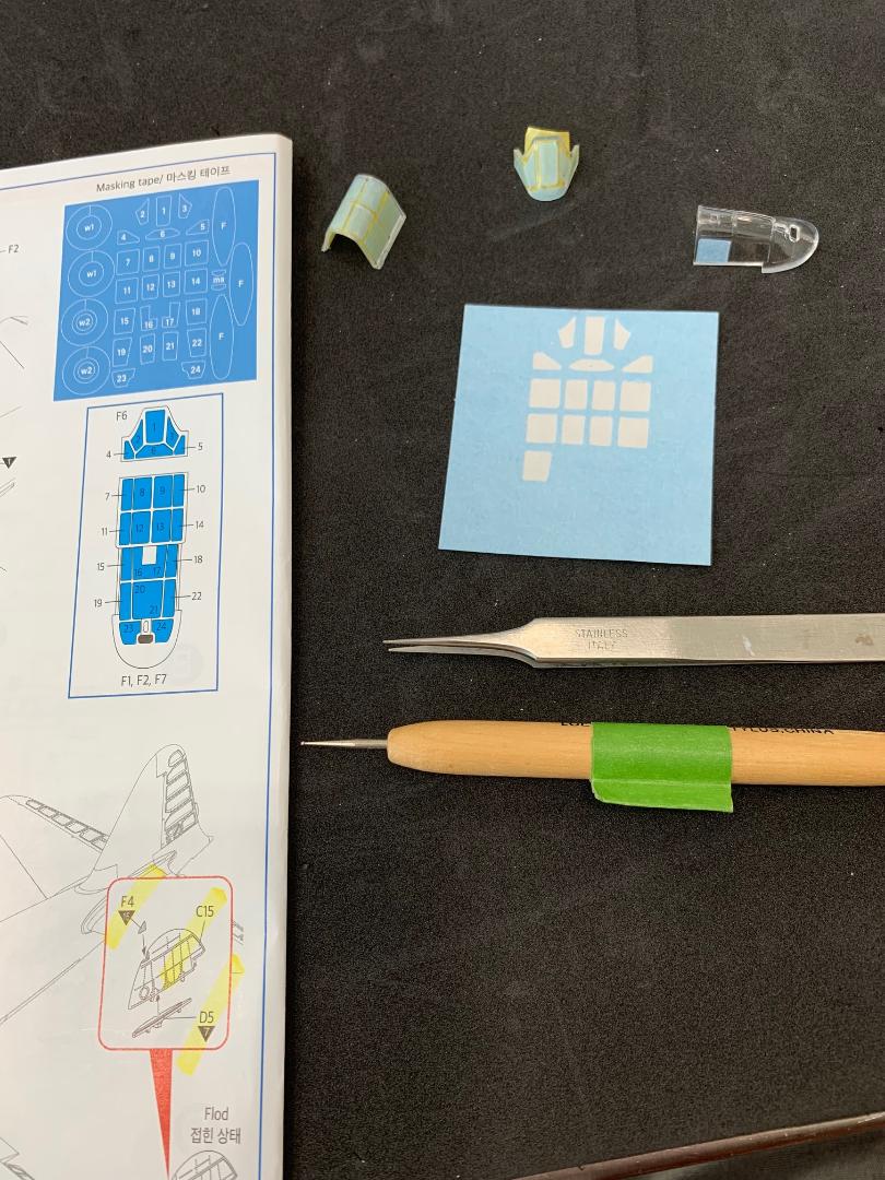
A small sheet of precut masks is also included for the canopy and wheels.
Instructions
The instructions are provided in two-8 page foldout manuals with 18 steps to the build. First page has a paint index for many of the more current and popular paint brands. Each construction step is shown in an exploded CAD drawing with parts and paint colors noted when appropriate. Four pages of Manual 2 include full color plans and profiles for the various markings for the aircraft that can be modeled from this kit. The last page of Manual 2 shows the parts trees layouts.
One very nice feature is each sprue has its alpha identifier molded into a tab in the corner of each sprue. Not just a small raised letter but a large open form making identification of each sprue an easy task. Very thoughtful.
Construction
Before starting the assembly and painting it really pays to review both manuals and study each step carefully to determine the painting and assembly sequence. I painted many of the parts separately beforehand.
Cockpit
There are eight sub-assemblies that make up the cockpit, not including the parts fitted to the fuselage sides. Each sub-assembly is show with an exploded view of the parts with directional arrows to the attachment location. Here, a careful study of the plans is important to place the parts as there is a lot going on in a rather small space. In a few instances the orientation and fit of parts requires a test fit to get things right. The smaller parts are challenging to handle and place, but in the end everything worked out.
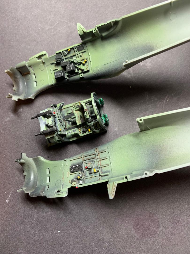
Once the cockpit tub and sidewalls were assembled I airbrushed Tamiya XF-1 flat black onto all surfaces, followed by XF-2 flat white applied vertically on the parts. This was followed by Tamiya XF-71. Details were painted with Vallejo Model Air colors.
I had a set of Eduard IJN seat belts that I used for this build.
Fuselage
When it came time to fit the various parts to the right side fuselage only one part (A6) gave me a difficult time to fit properly. Its counterpart (A5) on the left fuselage side fit with out any problem. The remaining small parts each required some effort to remove the attachment point spur. Being small in size it was difficult to hold the parts, but patience prevailed.
The instrument panel was fitted to the cockpit tub. The instructions include a line drawing side view of the cockpit tub and this was very help in getting the correct fit. The cockpit sub-assembly was set in place and the fuselage sides glued together.
Manual 2, step 17 shows parts B13 abd B14 ( the tail portion of the fuselage) being glued together and fitted to the assembled fuselage. I saw this as a possible opportunity to result in a step between the assembled fuselage and tail section. I glued part B13 to the right fuselage half and part B14 to the left side. The fuselage seams were tight and flush but I did find a bit of a step at the top and bottom sides of the horizontal stabilizers fuselage fairings. A touch of Tamiya white putty and some minor sanding corrected that fit.
The fit of the horizontal stabilizers to the fuselage was almost perfect. A hairline gap was apparent but can be easily filled with an acrylic putty.
Step 7 has parts A12 (top of fuselage front) and A20 (guns) fitted together and set onto the top of the assembled fuselage. I could not get this small sub-assembly to fit either by dropping in place or by sliding front-to-back or back-to-front. Part A20 was in conflict with the fuselage halves. I removed that part and the part A12 fit in place, snug but it fit. I would replace the gun barrels with brass tubing later.
Engine/Exhausts/Cowling/Propeller
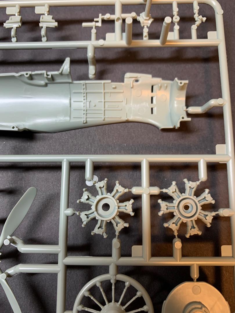
The engine assembly starts with the two banks of cylinders that will sandwich a poly bushing to secure the propeller shaft. Once the parts were cut from the sprue and cleaned up I airbrushed Tamiya flat black onto the surfaces, then dry-brushed Rub-n-Buff silver onto the cylinder heads.
The propeller is made up from four parts. The spinner back was left off for the time being and was air-brushed along with the assembled propeller with Alclad Aluminum over a glossy black base. I had earlier painted the back side of each propeller blade with Tamiya XF-64 Red Brown. The propeller and spinner were assembled next.
The exhausts are two separate parts that are glued to the rear side of part A13, the engine compartment rear bulkhead. First, I painted the exhausts flat black, and when that was dried I dry-brushed burnt sienna oil paint to represent discolored surfaces.
The cowling assembly is comprised of five parts, with the option to have the cooling gills open or closed. I used the open gills parts. The exterior surfaces of the cowlings were painted with a 10:2 ratio of Tamiya Flat Black XF-1 and Dark Blue XF-8. The interior of the cowling and open cooling gill were first painted with Alclad black primer, followed by Alclad Aluminum, and lastly by a 1:1 mix of Tamiya clear blue and clear green.
Wings
The wing construction begin on pages 6 and 7 of manual 1. Page 6 shows the landing gear wells for the flying configuration while page 7 shows the landing configuration: this could cause some confusion, but with a thorough review of the instructions before starting the assembly would avoid any conflicts. Once the gear wells were fitted in place the top wing sections were glued in place.
Step 14 shows the installation of a poly bushing placed in a position on the interior surface of the bottom wing part which is then capped off with a plastic disc to hold the poly bushing in place. The drop tank in held in place with this assembly allowing the tank to be removed for display if so desired. The appearance of the filler cap on the top front of the tank was improved with the addition of a small plastic disc glued in place.
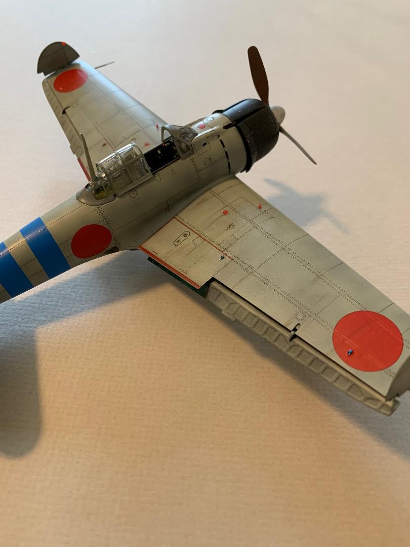
I finished the wings with the tips folded. I did not use the kit pitot tube, but rather used a short length of small diameter brass tube with a metal rod in the center. The wing flaps can also be posed up or down.
The belly tank was assembled and painted. After the model and belly tank were painted and decaled the tank was fitted in place as noted above.
When fitting the wing assembly to the fuselage I found an interior obstruction that would not allow the wings to fit properly, resulting in a gap at the front and noticeable steps at both wing roots. The front of the cockpit assembly appeared to be in conflict with the tops of the wheel wells. With careful and selective trimming of the cockpit front rails and cross member, plus sanding and scraping of the tops of the wheel wells, I was able to get everything to fit. The material removed from the cockpit sub-assembly was not apparent when viewed from the top.
Landing Gear/Wheels
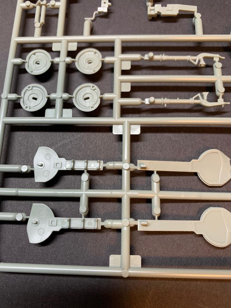
The Zero's landing gear is quite simple and the kit provides a single part for each main gear, while each wheel is comprised of two halves with flattened bottoms. Cleanup of the wheels' mating surfaces is a must for a good fit to avoid a gap in the circumference.
The main gear doors did have two ejector pin marks in each lower portion. I filled the depressions, but later saw that the wheels would cover most of the marks. The interior surfaces of the wheel wells and gear doors were painted in the same fashion as the engine cowling interior noted above.
The main landing gear, tail wheel, main gear wheels and arrestor hook were first painted Tamiya flat black, then lightly dry-brushed with Rub-N-Buff silver.
Canopy and Windsceen
The kit offers an option for an open or closed configurations. Although the clear parts were nicely molded and clear, I still dipped the parts in Future and allowed them to cure for a few days.
Masks
The kit includes a set of masks for the wheels, the canopy, and the back side of the propeller blades. The instructions include a map of the parts with numbers and a complementary canopy showing the numbered masks in place. Easy peasy. The canopy masks are for the exterior side only. I spent almost an hour applying the masks to the clear parts. The most challenging part was finding each mask on the sheet. There was no clear definition as to the edges of the masks. I used a sharp No 11 blade's tip to lift each mask once located, then placed the mask in the correct location with needle-nose tweezers. The mask was then burnished in place. One or two of the masks were too small for the clear part and I used Tamiya Kabuki tape as a supplement. I also masked off the interior of the clear parts to avoid possible paint overspray.
Painting and Weathering
As noted above several of the sub-assemblies were previously painted as part of that assembly.
Once the model was assembled, I washed the exterior with warm water and a drop of Dawn detergent, and allowed the model to dry overnight. The model was then washed again with an alcohol wipe.
I first masked off the cockpit and wheel wells. I used Tamiya FX-1 Flat Black thinner with Mr. Color Self-Leveling thinner as a primer for the exterior surfaces.
Decals and Application
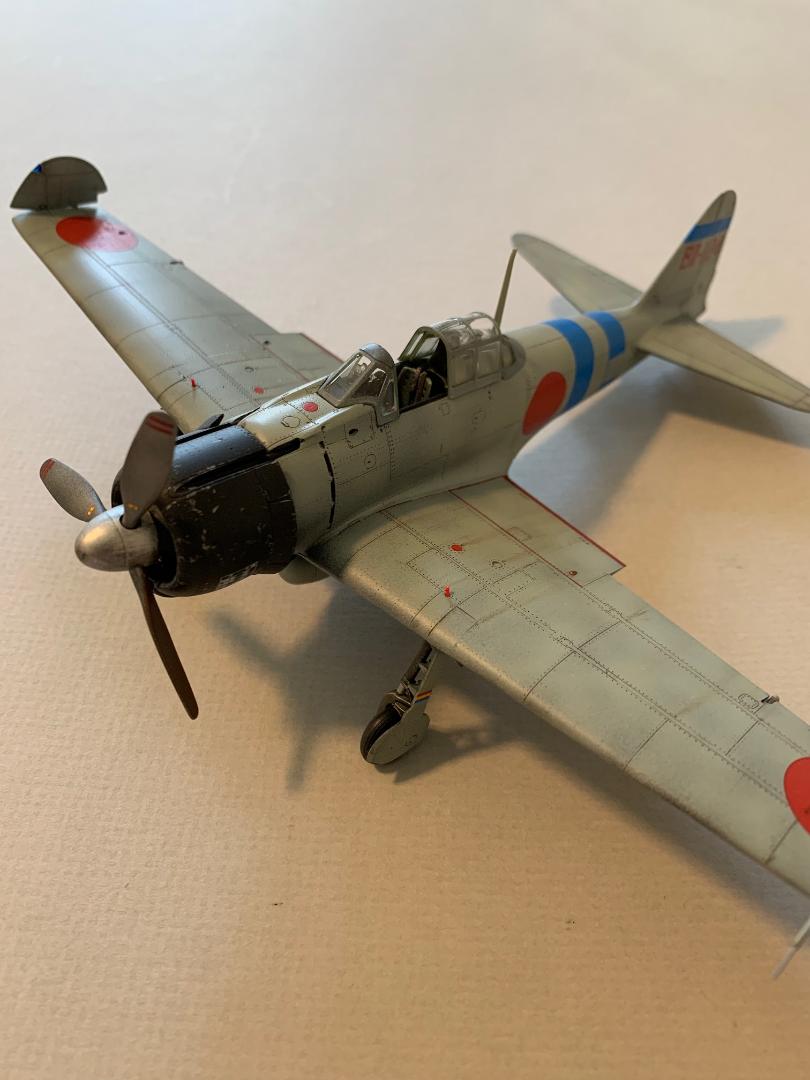
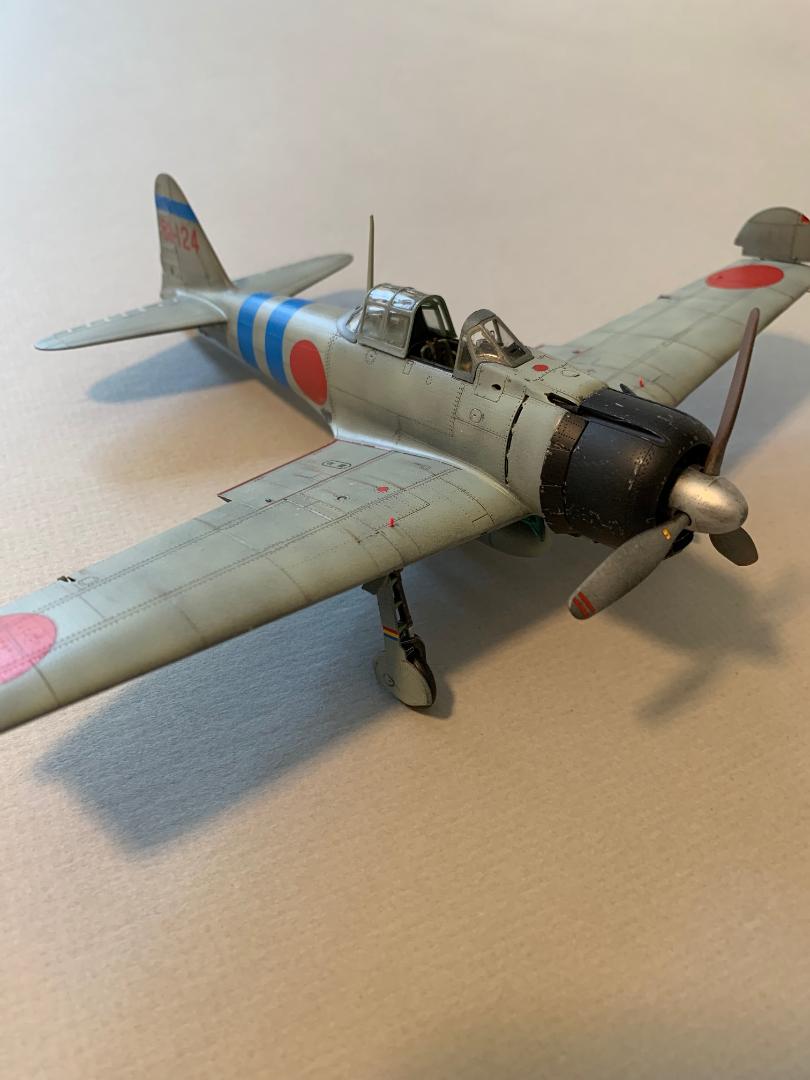
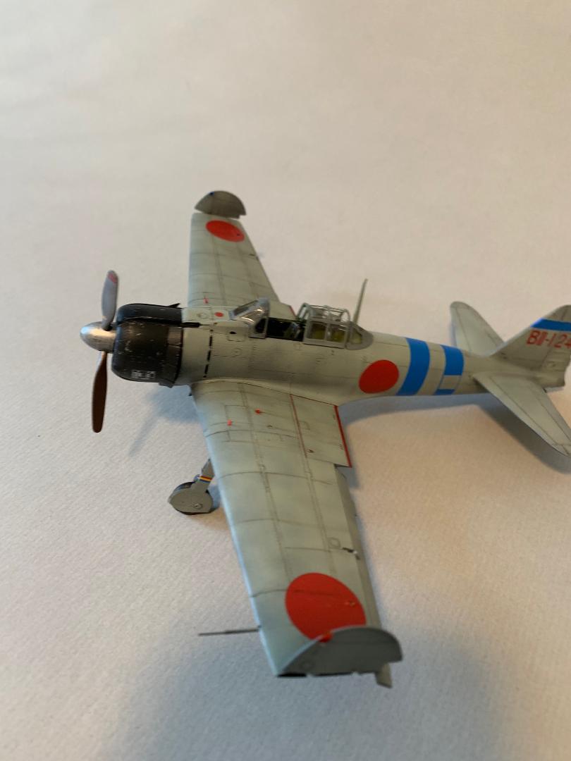
The small decal sheet has marking for five aircraft. I chose the markings for the A6M2b Model 21 for IJN Hiryu, 2nd Carrier Division. The instructions have plans and profiles locating the common markings and two-sided profiles for the individual aircraft. All aircraft are IJN grey.
The painted model was given several light coats of Future to seal the finish paint and provide a gloss coat for the decal’s application. The decals were cut out individually and dipped in water. Within a minute they were ready to position on the model. I used MicroSet to locate each decal and MicroSol to snuggle them down. The kit decals performed nicely, conforming well to the recessed details, even the micro-rivets.
Bringing it all Together
The main landing gear with the wheels and gear doors were installed next. The drop tank was installed without glue, and the clear parts were fixed in place. The folded wing tips were next. The engine cowling and engine assembly were fitted last and I was finished.
Conclusion
This is a really nice kit. There are a lot of parts to deal with for this build which made it interesting and enjoyable. I found the instructions fairly easy to follow and quite detailed and informative. I was quite pleased with the end result. Academy has come a long way in quality and detail with their products.
Aside from the two fit issues (which may have been my own doing) the fit was quite nice. I was able to resolve both fit issues without the use of much filler and no visible exterior issues.
This is my first build of a newer Academy product, and I was quite impressed with the quality and detail of the plastic parts. The multi-manual instructions were busy, but clear for the work involved. The assembly went together quite fast and I was ready to start painting in about five days.
I highly recommend this kit.
I wish to thank MRC and IPMS USA for the opportunity to build and review this kit. This is a gem and the price is right.


Comments
Add new comment
This site is protected by reCAPTCHA and the Google Privacy Policy and Terms of Service apply.
Similar Reviews