
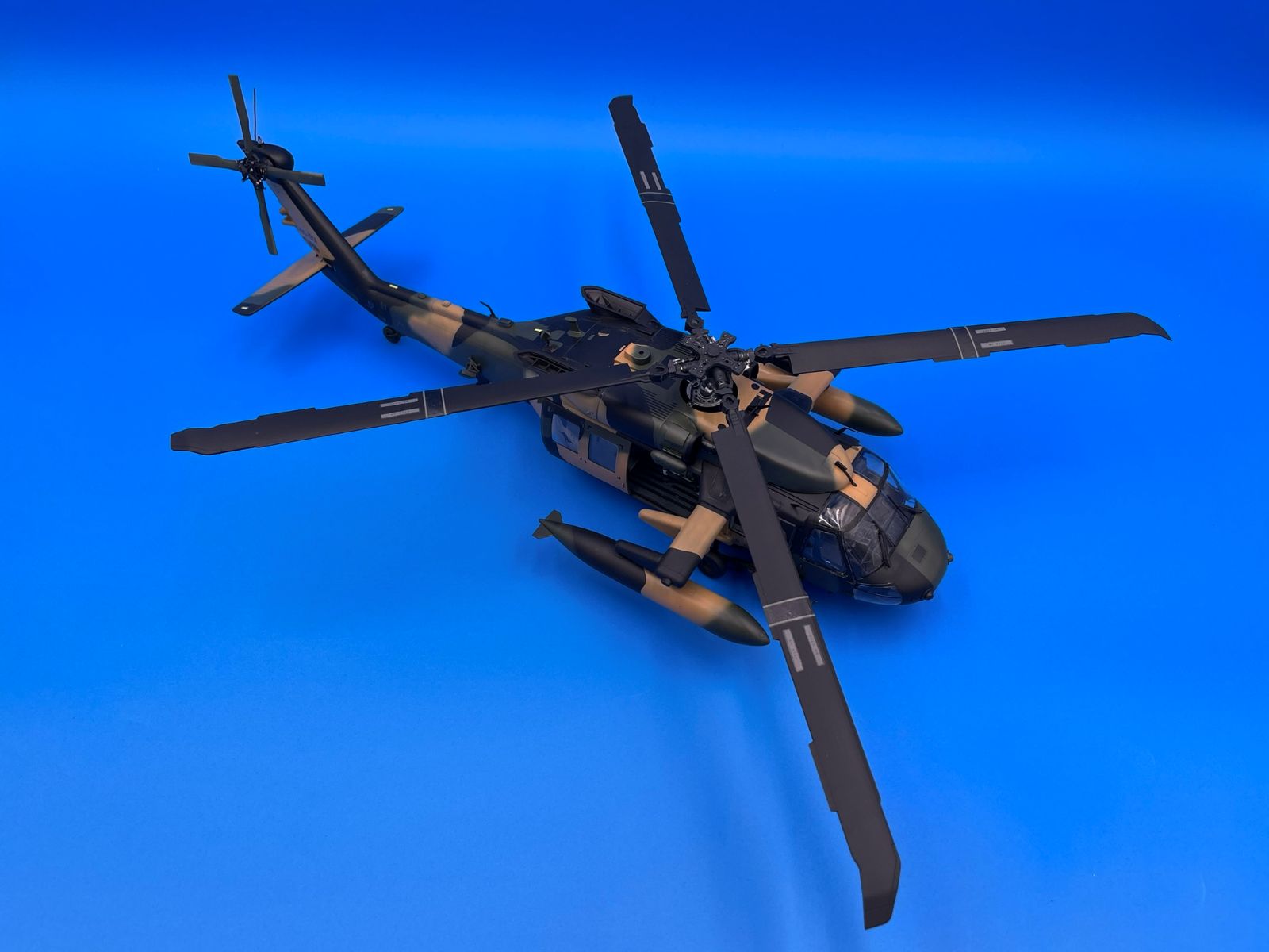
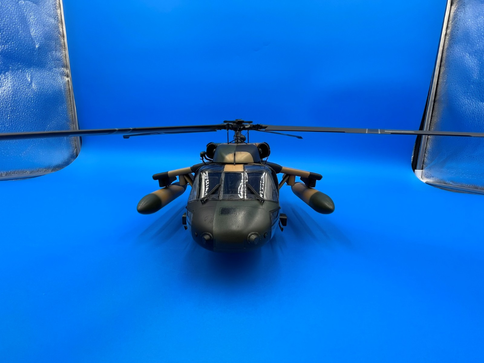
UH-60M Black Hawk
What really drew me to this release was the Aussie option! The Australians started getting the UH-60M in 2023, and traditionally they use it for long-range search and rescue in the Outback and over the ocean, making for some unique configurations. Academy has a long history with the Black Hawk mold, and they’ve taken full advantage of its popularity with new parts. In addition to the A60-001 import model, Academy has everything in this box to fit out a full Australian import version of the Black Hawk. Builds of the M seem few and far between, so I’ve tried to hit a lot of detail in this review for the competitive builder.
For everyone who wants instant gratification, let’s start with the pros and cons, then transition to the details!
Pros
- The unbelievable number of options on these sprues
- Shape
- Crystal clear parts
Cons
- Quite a few panel lines and rivets are faded or partially missing
- Assembly and fit of the troop box
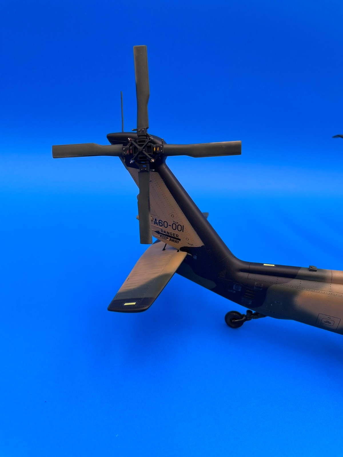
The Rotor
Spend a few minutes studying how part D31 mounts to the rotor assembly. The sketches make it a little hard to tell what the orientation should be. I ended up finding a good clear picture of the Rotor assembly to make sure I had the orientation correct. In hindsight, I would avoid assembling parts B59 and B63 until you are ready to install the rotor on the helicopter. On mine, the mounting location in the helicopter for part B59 was misaligned with the opening in the fuselage and so had to be extensively hollowed out in order to make it fit.
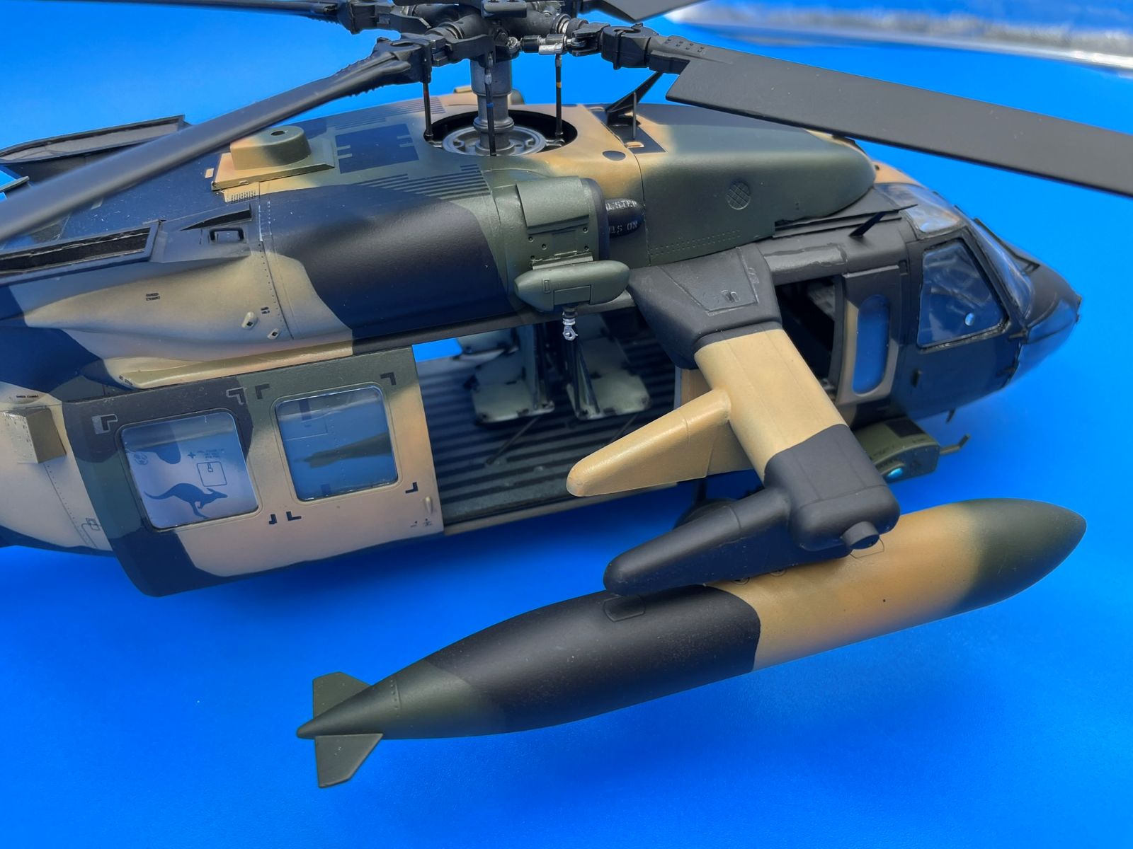
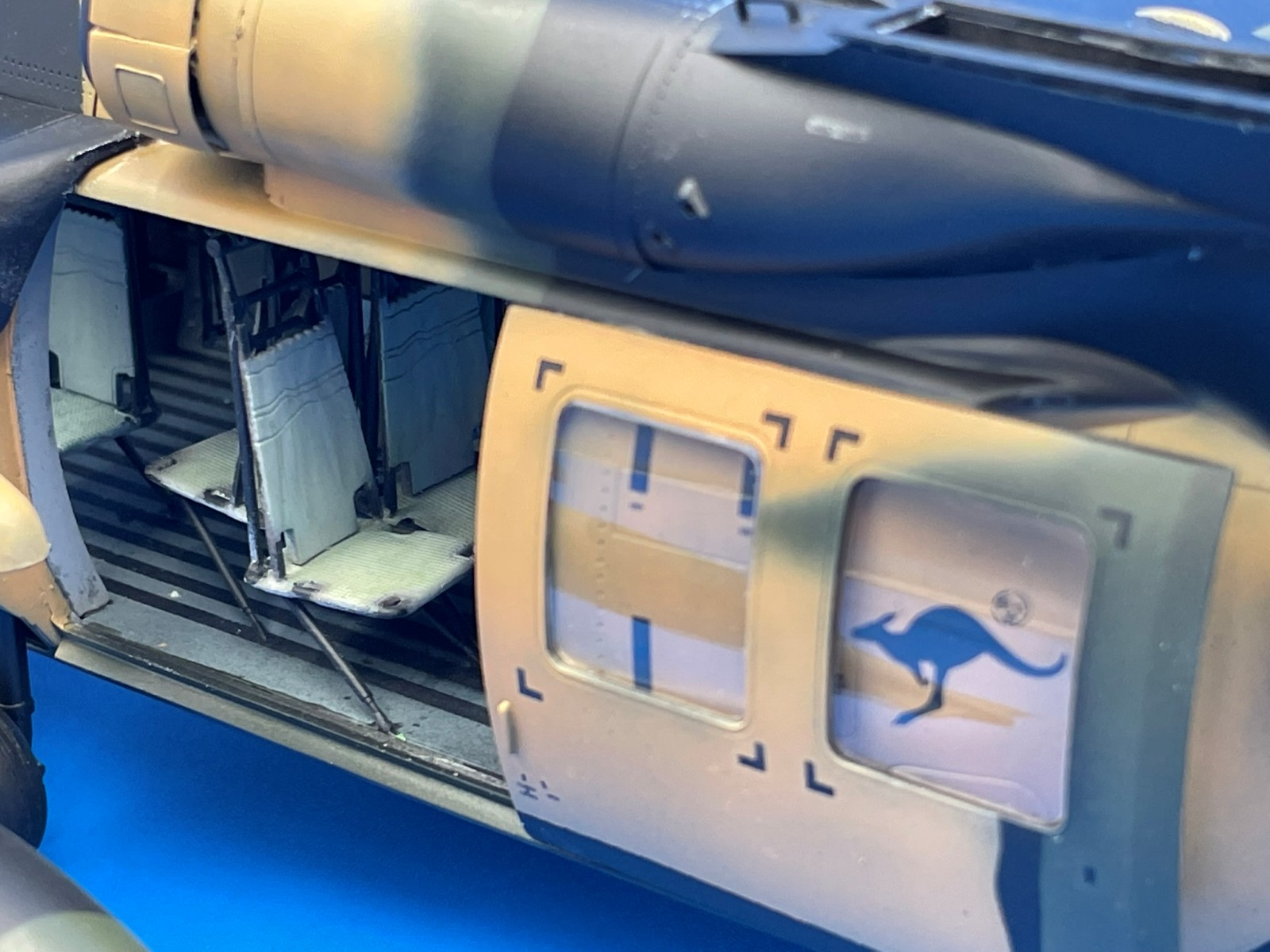
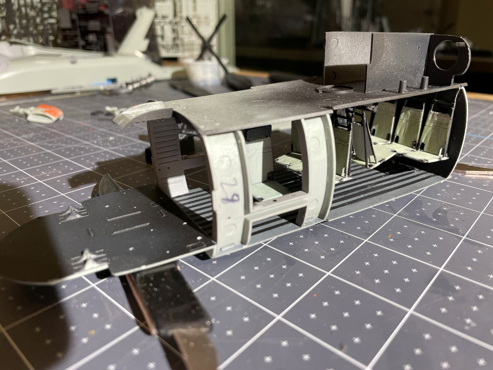
The Troop Box
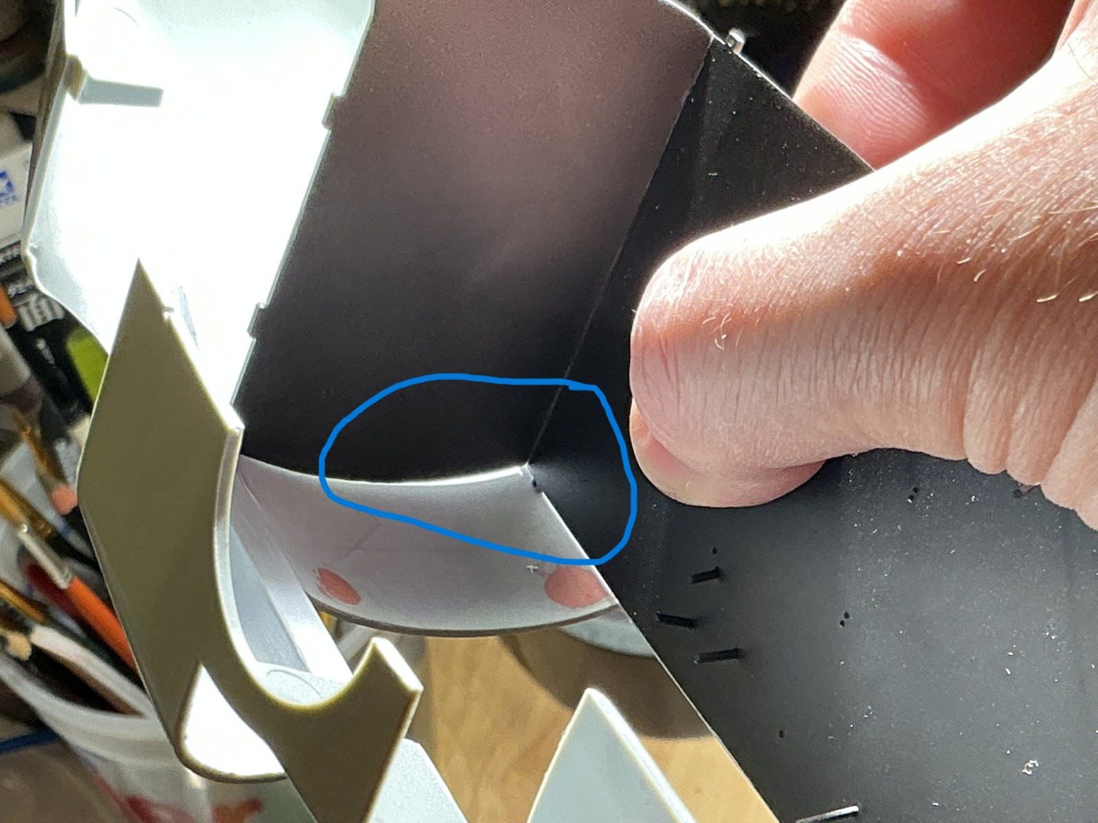
While not overly complicated, truly requires that you have five hands. The risk in assembling it the way the instructions show is that the support rods for the seats won’t line up correctly, or at the right angle with the floor, when you assemble it. The way I did it, which was to assemble the roof, add the seats without the supports, and then attach each support rod between the seat and floor, is that it’s very difficult to reach in with tweezers and place the supports without the seat moving and knocking the support free. In hindsight, I think a third option, similar to the instructions, might be the best, which is to have everything painted and ready to assemble, hang the seats in place from the top, and then use a thick cement or a white PVA glue that will maintain some flexibility to assemble all the seat supports at once and then flip it over and mate it with the bottom of the troop box. The alignment pins for the seat supports are exceptionally small, so be careful not to paint over them if you’re doing that before installing all the seats. I had to file out the vertical supports for the seat backs in order to get them to fit nicely. The seats themselves have great detail to them and some tape seat belts would give an accurate representation. Make sure that you do a bit of dry fitting of the troop box to the fuselage. There is a pin location on the back of the troop box for that last row of seats that sticks out beyond the edges of the box. This is not shown in the instructions. I found that it interfered with the fit to the fuselage and did not allow it to close completely. Once those seats are glued in place, begin filing down the edge of that pin, and you can get it to fit without totally removing the pin. Overall, I found that I had a 1mm gap on both sides of the troop box that needed closed up. It’s possible to squeeze it closed, but it changes the profile of the fuselage if you do. There are a number of gaps along the vertical walls as well that may need to be closed up depending on which options you choose for outriggers or door position.
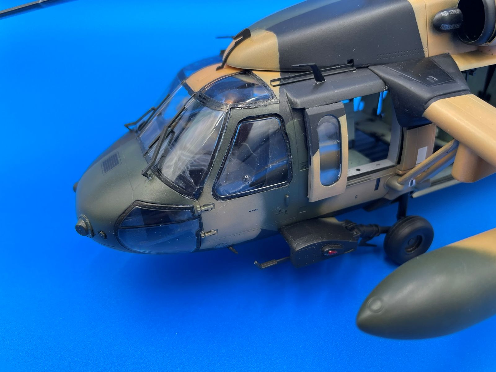
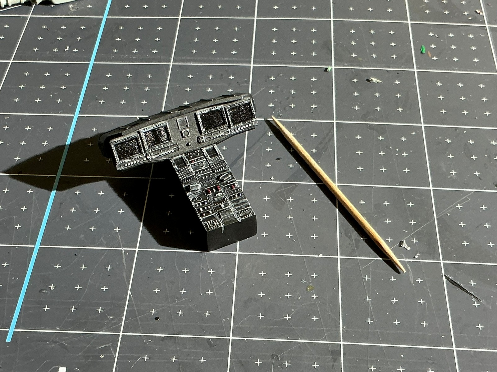
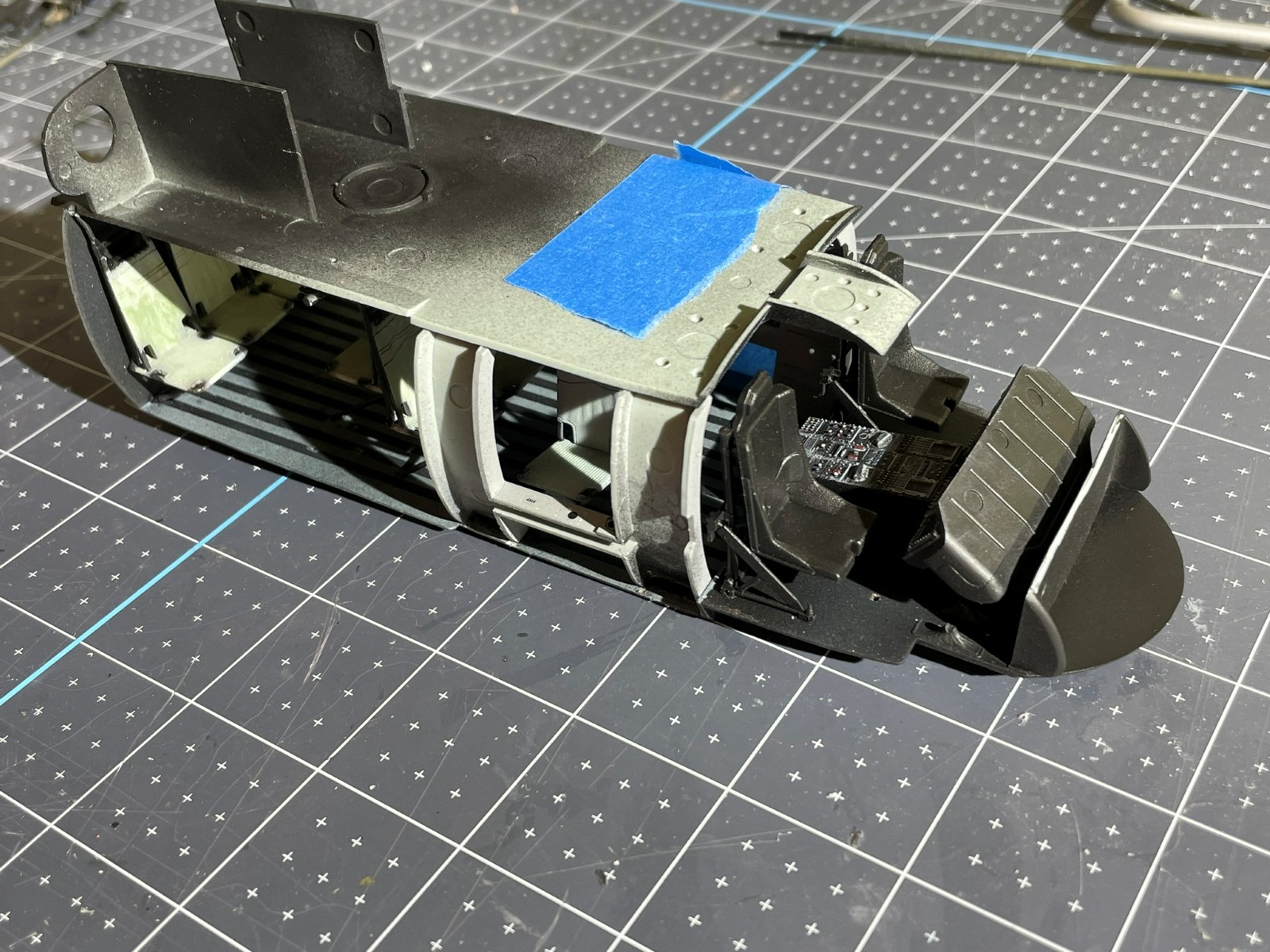
The Cockpit
Assembly here is pretty straightforward. There are just a few notations with respect to the instructions at this point. The callout number for the foot pedals is reversed. There’s no reference for applying decals to the instrument panel at this point. Make sure you remember to do this, because later you won’t be able to.
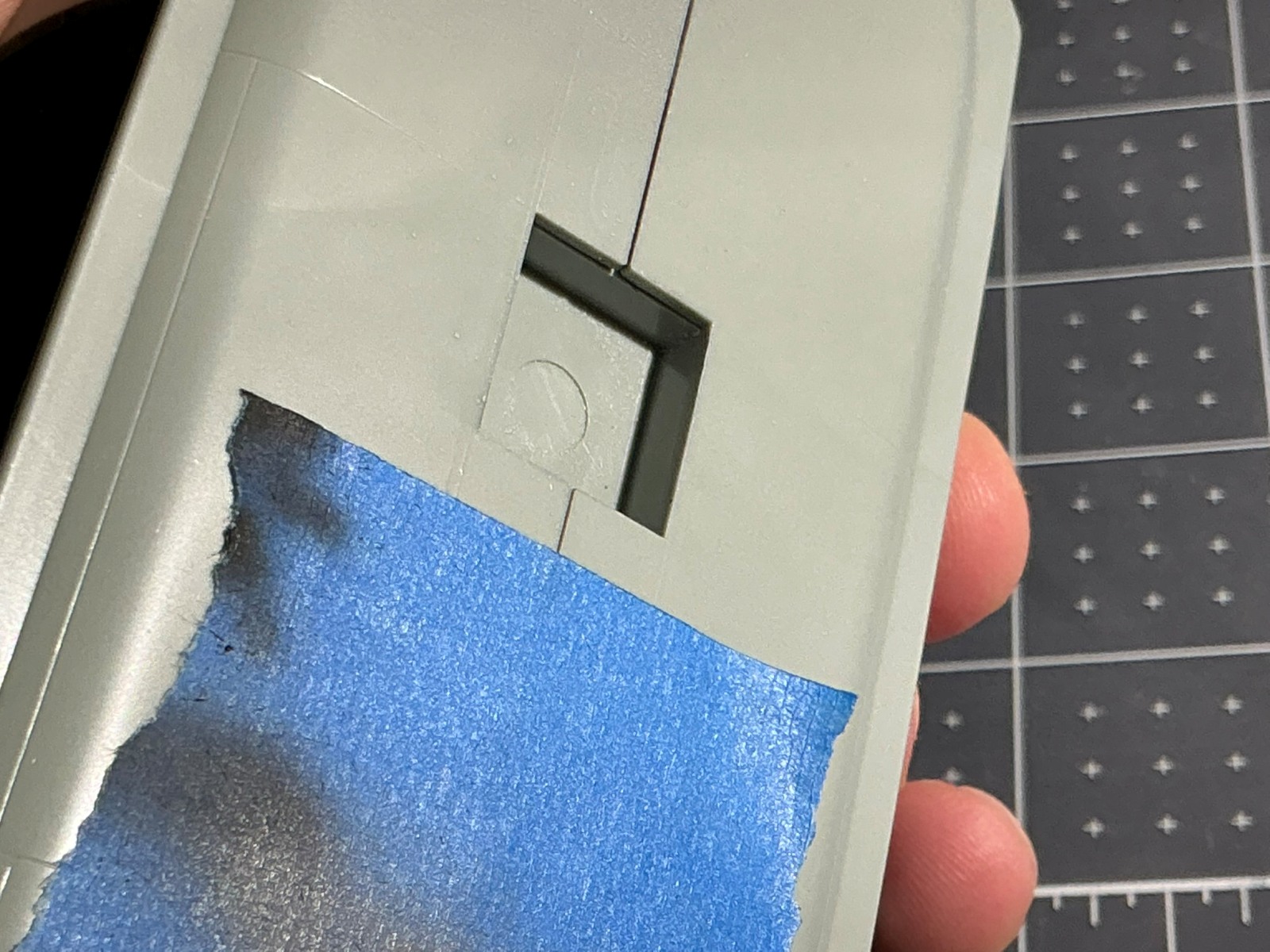
The instructions are a bit confusing when it comes to the doors. Step 11 shows assembling in three steps; first it shows cutting the door completely out(in the image the runners are already removed from the window), then it shows cutting the runners out from the window area(with the door still installed in the fuselage), then assembling the entire fuselage and troop compartment (but the door is shown on the fuselage like it was never removed). I chose to leave the door installed and to leave the runners in the window for additional support. Doing it this way, I had no issues with the cheek windows or the main windscreen alignment. I would say you need to check the windows for the door before assembling the fuselage so that you can open the frame up so that the window will fit. If you don’t do this, all the riveting is completely covered by the door frame. After writing all this, and knowing that the windows didn’t fit in the door, I’m wondering that, maybe the instructions are trying to say, is that you have to cut the frame support along the angled front of the doors so that the window will fit when you get to it. Double-check the orientation of the decals on the doors because I believe the part numbers are reversed here. All the references for the attachments to the outside of the fuselage are excellent. One triangular antenna located on the bottom edge of the pilot doors is not referenced in the instructions. It is present on all the UH-60M helicopters I found pictures of. Part G39 appears to be the correct antenna. With that one exception, the options match the different helicopters and the measurements for installation looked to match actual pictures.
The Engine
I really wanted to make this visible like it shows in the instructions. The problem comes from the overall fit. If you want to use the engine, make sure that you are fitting it up to the mounting points and the bulkhead before gluing it together. If you don’t make major cuts and adjustments, it does not fit when assembled as the instructions show. Since I didn’t do this, I ended up scrapping this part and just using the engine cover in place. The fit of the engine cover, by the way, is very good.
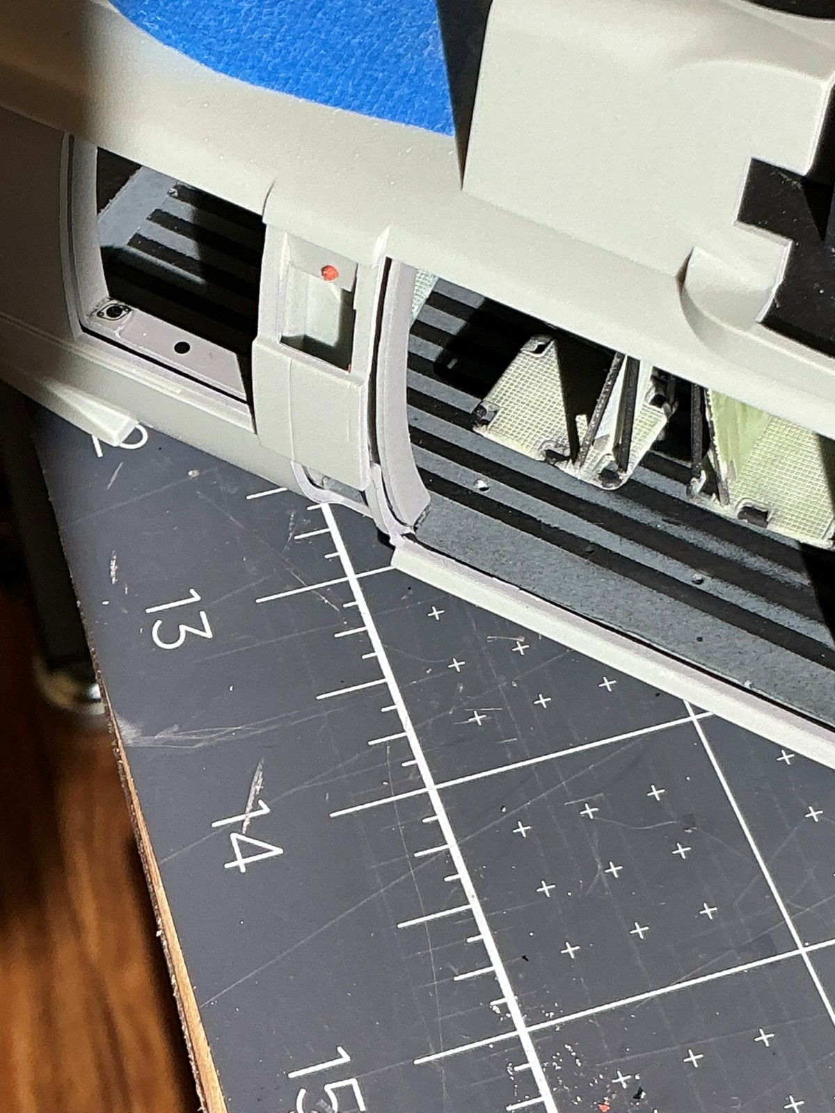
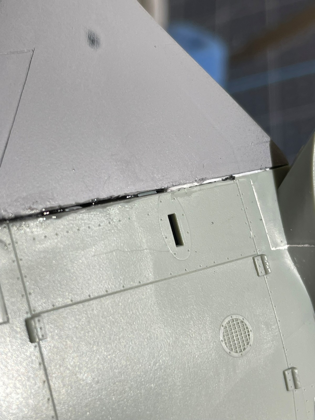
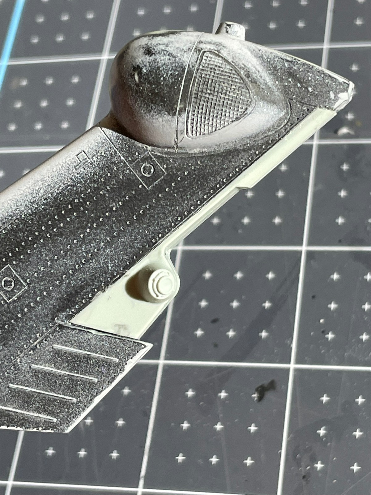
The Intakes
When you get these done, they can look very nice. There are no alignment pins on them for assembly, so give yourself plenty of time for the glue to dry… Otherwise, they might slide apart. Ask me how I know, Lol! Note that they are different side-to-side, so pay careful attention here to the instructions. The intake ring, part B66, fits pretty closely and just needs a little bit of sanding along the backside to fit well. I ended up sanding the top edge of the intake body to match the ring. The important part with these is going to be cleaning up the inside of the intake because, as it turns out, this is all very visible on the finished model. To fit the intakes to the fuselage, I just had to do a little sanding on the backside of the intake bodies so that they lined up well. Remember when assembling, that little nose on the intake is not supposed to be flush to the fuselage, there is a gap by design.
The Exhaust
This is all assembled very cleanly and is one of the reasons I think the overall fit of this model is a Pro. On these parts, there are no alignment pins and so you need to work slowly and let individual parts dry before assembling the next part in order to make sure everything stays aligned. I did some dry fitting to the fuselage as I went, to make sure that the angles were correct. This is the most important part of this single assembly. The rear of the exhaust goes together more like a pyramid of parts, so without dry fitting, it’s possible to get the angle incorrect, and then it won’t mate to the fuselage correctly, leaving you a big gap to fill. When you make part O54 to the fuselage, I would suggest a long alignment support be glued in for the entire length. Without it, there’s a good chance that you will have a wavy joint. Pay close attention to fit here. My O54 was short and a long gap needed to be filled. This is one of the new parts and the length appears to be shorter than the piece it replaces. A last note in reference to the decals that go in this section later. I would mark the orientation of part O8 in reference to part O7 based on the decal. This way, when you go to apply the decal, it will fit, and you won’t have to cut it and try to add pieces of black decal to make up for the gap.
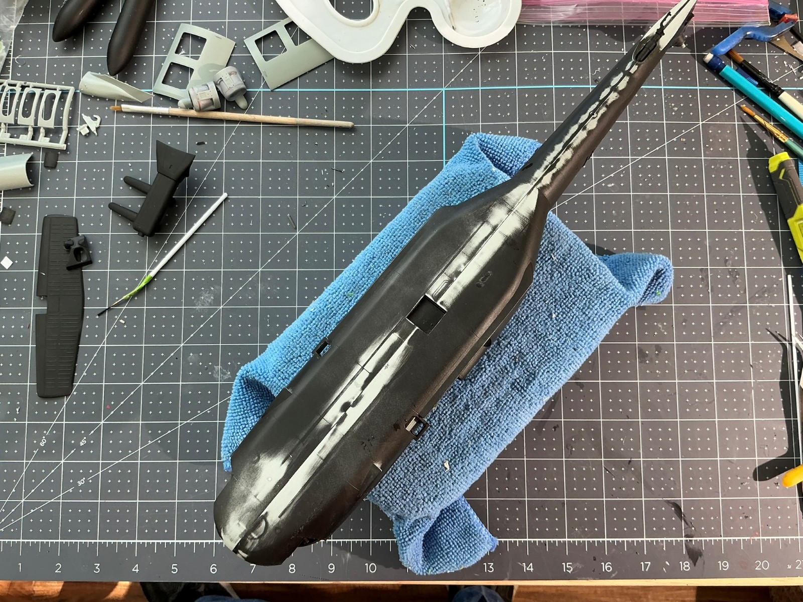
The Fuselage
With the addition of some alignment support tabs along all the long flat sections of the joint, the fuselage goes together extremely well. I ended up with no major offsets or gaps. One thing I did to help this out though, was to sand off approximately 1/32nd of an inch off the box for the lifting lug. This box causes the bottom of the fuselage to bow out, and you’ll end up with a gap to fill along that whole bottom joint. Once I trimmed it down, everything matched up nicely. Now, the location of that lifting lug box doesn’t quite match the opening in the fuselage. I checked this by dry fitting multiple times and the alignment of the troop box with the door opening doesn’t match the alignment of the lifting lug with the opening in the fuse halves. I opted to add a 16th inch shim to the front of the lifting box and make the troop box look clean and aligned. The last quandary I had was, what is part B62? I have no idea where it goes based on the arrow in the instructions and I couldn’t figure out what it was to even look for it on the real helicopter. I left it off.
The Final Fuselage load out — steps 15, 16 and 17 cover the doors, windows and final attachments to the fuselage like wire cutters and windshield wipers. Other than the door windows mentioned previously, everything here goes together very well. All the other glass fits well and snaps into place perfectly. One note on the inside of the sliding doors for the fuselage, the reference to the decal placement is reversed. Make sure that those decals go on in relation to the outside location of the door handle.
The Manual 2 (their phrase not mine Lol) – This is a great addition by adding color to show each configuration, the final assembly steps, and the part tree layout. Again, these parts all go together very well. A few watch-outs include the wire cutters on the wheel pants are shown installed backwards or upside down, depending on how you view it, and the main rotor alignment to the fitting on the fuselage may be off center and not allow it to fit. I did not install the main support rod for the wheel, part A16, until this step. There’s really no reason to put it on earlier and by waiting until you install the wheel and wheel pant you can make sure that the alignment is correct and that the wheel will sit straight up and down. There are a couple of options for different birds in this step, so check your references for the specific helicopter you are building.
The Decals
These decals are super thin and blend right into the fuselage when you get them to lay down cleanly. Due to how thin they are, be careful in application because they do roll over on themselves easily when they are this thin. The other thing I learned is that they are very sensitive to even Micro Set, and they start to melt onto the fuselage with anything except water to place them. Lastly, think about sourcing a previously released decal sheet to pick up rotor warnings, drop tank and miscellaneous decals that have been removed to make space for decals needed on the new model.
The Finale
This is really a great-looking helicopter when finished up! Good detail, tons of options to build practically any bird out there, and an overall fit where it counts, at all the major joints. That makes this model look super clean upon final painting!
Many thanks to MRC and IPMS for providing me this model to build and show you 👍

Reviewer Bio
Chris Vandegrift

When Chris isn't modeling he's restoring old cars or doing home remodeling in his spare time. Both have helped improve his modeling. "Having learned to paint cars, quite a few of those techniques apply to priming and painting my models," he says. Chris used to build aircraft exclusively, but has expanded into ships, science fiction, armor and cars. A member of multiple IPMS clubs in Ohio including Akron's Ed Kinney Chapter, Wright Field and Cincinnati Scale Modelers, Chris started building models when he was about 7. Chris lives in Cincinnati Ohio; a Mechanical Engineer by trade, he's the head of Operations and Engineering for a company that makes pumps. He's been married to his wife Jane for 30 years; they have four kids ranging from 20 to 34.
Comments
Add new comment
This site is protected by reCAPTCHA and the Google Privacy Policy and Terms of Service apply.
Similar Reviews