
T-54-2 Model 1949 Soviet Medium Tank
Background
As production ramped up, it was discovered that the T-54-1 Model 1947 had a number of technical issues. This lead to relatively few vehicles being produced, and production ceasing quickly, to be replaced as the problems were sorted out with a modified variant, the Model 1949. This second variant had a different turret configuration than its predecessor, the fender mounted machine guns of the Model 1947 were deleted, and the fender mounted cylindrical fuel tanks (as seen on late model T-34/76 and T-34/85 tanks) were replaced by a rectangular design.
This is the second T-54 kit from MiniArt that I have had the great pleasure of reviewing for IPMS/USA. The first, MiniArt Kit #37003, was of the T-54-1 Model 1947, the first production variant of this important Soviet Cold War warrior. For this review, see here: T-54-1 Review
The T-54-1 Model 1947 kit was an “Interior Kit”, which meant it included an almost full interior: driver’s area, hull shell stowage, and a superb engine, plus a fairly complete turret interior. The kit under review today is a stripped-down version, being minus the interior. I believe most modelers would be quite happy to avoid the interior of the other kit, since it was a heck of a lot of work, and most of it can’t be seen once the model is “buttoned up”?
What’s in the MiniArt Box
- 48 sprues large and small of gray plastic parts (
- 1 sprue of clear plastic parts
- 1 frets of photo etched brass parts
- 1 sheet of water slide decals with 6 different marking options
- 1 black and white instruction booklet, 16 pages, with 69 assembly steps and incorporating a color markings and painting guide
Before You Start Construction
Before you start construction of this kit, you will need to figure out a very important matter: how to create a sane system to keep track of where each sprue is on your workbench and the parts thereon. Even with “fewer” sprues than the “full interior” kit (74), it is quite a task! I came up with the idea of getting a large document storage box, and a bunch of large file folders. These were then labelled “A”, “Ba”, “Cb”, “Hk” etc and the appropriate sprue(s) slipped into each folder. Then as you need a part, you reach into the storage box and pull out the appropriate folder and the sprue(s) contained therein.
Under Construction
The MiniArt T-54 series of kits are a tour de force of model engineering. Whether you tackle a full interior kit or one that is minus the interior detail, each model is loaded down with parts that contain the highest levels of detail, and, thanks to CAD, that fit together surprisingly well for incorporating such a smorgasbord of parts, both plastic and photo etched brass. Everywhere you look you find crisp bolt detail, fine weld detail, and great representations of cast metal. Strangely for a new kit, there was flash present on various items, such as very occasionally on the road wheels. Absolutely nothing to be alarmed about, as a few simple swipes of the hobby knife removes the offending plastic. However, it is a tad surprising given these are new molds. I noted no ejection pin marks on any parts that are visible once construction was concluded. One note however before construction begins: make sure you have a VERY fine razor saw blade.
Why? Because if there is one “fault” to MiniArt kits that I have built, in terms of ease of assembly, it is that some very fine parts are attached to the sprues by masses of sprue attachment points. Even though the plastic used by MiniArt in this kit is fairly robust and flexible, there is a risk of damage if you try to remove these finer parts from the sprues with regular sprue cutters. Be warned!
Construction of the kit starts with the lower hull plate, part A42 and the (workable if you are careful) torsion bar suspension parts. Study the kit instructions carefully, and highlight the parts that you need to keep free of glue (so that they remain working). If these workable parts bind up with glue, you will have problems later. Carefully following the diagrams, Section 1 through 10, and making sure the glue doesn’t go where it isn’t supposed to for the working parts, makes for these sections being trouble free.
Section 11: care is required in getting the parts in this section, KC2 (x4) and KC3, to attach to the model such that the suspension arms remain free moving. Section 12 repeats the process for the other side of the hull.
In Section 13, the instructions ask the modeler to remove sections of plastic from part A2. You have to measure, and then cut/file away various small sections, making a chamfer. Measure twice, cut once. You will be asked to do similar cutting/filing in Section 16, part A1.
Section 20: this is where the modeler glues together the three main sections of the lower hull: the lower hull plate, and the right and left sides of the lower hull. It is advisable to have handy at this point part Ba5, the sloped glacis plate part. Also have handy parts C32, C34, and Ca30. These are the rear hull plates. Utilize the rear hull plates and glacis plate at this time to make sure that the lower hull plate and left and right hull sides are all lined up properly. If they aren’t, you will experience gaps later when it comes time to actually install parts C32/C34/Ca30.
Section 21: the road wheels. These are the so called “Spider” type, early versions of which began to appear on T-34/85’s at the end of WW2. The detail on these is amazing, including the subtlest of weld marks. Slightly (but only very slightly) let down by the need to remove small amounts of flash from some of the areas of these parts. The road wheel assemblies are a total of five parts. There are the two actual road wheels themselves, parts Hk5 and Hk6, plus a small disk part, Hk3, which goes on the inside wheel (Hk6) which butts up against the hull. Then there is the outside wheel’s hub cap, part Hk1, plus a mounting pin, Hk4. I mention all this because the parts are interchangeable, and yet they are not. What I mean is that when you are gluing the parts onto one another, they fit two ways. The right way and also the wrong way. And if you glue them on the wrong way in Section 21 (the first three parts), they won’t fit properly when you go to glue on the last two parts, in Section 22.
Section 22 has the modeler assembling the four-part drive sprockets. If at all possible, keep these free moving, as it helps with the installation of the individual link tracks later. Likewise, the idler wheels, each six parts, and their mounting arm, part Kd2, should be kept free to move/pivot to help with track installation.
Sections 22, continued: mounting the road wheels to the suspension arms. Start by gluing the First and Fifth place road wheels to first one side, and then the other and applying glue to the suspension arms so that they are glued in position solidly and at the correct ride height. I use a jig to hold the wheels in place so that they are lined up exactly front to back and at right angles to the hull. I let the glue set for about 15 minutes on the first side, then work with the two wheels on the opposite side. Then clamp the first side in the jig again for a further 15 minutes, and repeat with the other side again for 15 more minutes too. Check while this is going on that all four corner wheels sit on a flat surface evenly. Allow the glue to set overnight. Return the next day and install the second, third and fourth position road wheels, again using a jig to make sure they are all lined up both front to back and at right angles to the hull. As with the first time around, allow the road wheels to set up for 15 minutes and then do the other side, clamping them in their jig for 15 minutes. Switch sides, and clamp for 15 minutes a side. Making sure once again that all the wheels are touching a flat surface evenly.
Sections 23 through 26 involve the attachment of various small fittings to the front glacis plate and the rear hull plates, and then the installation of these onto the main lower hull unit. Make sure you drill out the various mounting holes from the inside of the glacis plate and rear hull plates at the appropriate times during the assembly sequences. In Section 23, you install part Ca3 on the rear hull plate Ca30. Ca3 is a very fragile, spindly part, attached to its sprue way too many times for ease of removal. CAREFULLY remove it from its sprue utilizing the UMM razor saw, and then equally carefully, using a sharp hobby blade and sand paper, remove all the burrs where the part attached to the sprue. If you are careful, the part will remain intact for installation onto the rear hull plate.
Section 27/28: upper hull main plate and fittings. The main upper hull plate, part F11 is a near perfect fit to the lower hull unit. Sections 29 through 33 involve the rear upper hull plates and their fittings. There are three lovely photo etched grill parts, PEa37 and Pea38 (x2). Carefully remove these from their PE “sprue”, and carefully clean up the attachment burrs. These parts are very easily bent by flexing, so as I say, be careful. Mount them extremely carefully with very low tack tape onto some small pieces of cardboard or popsicle stick so that they can be primed and painted on their own. Make sure to mist on the primer and the paint, and have the parts mounted so that the primer/paint doesn’t build up, causing the fine mesh to become clogged. In Section 33, parts C1 and C2 are yet more parts that are attached excessively to their sprues by multiple attachment points. Unfortunately, my luck ran out here, and I shattered these parts attempting to clean them up. Thankfully when this happened, I managed to hold onto the parts, and thus denied the Carpet Monster an easy lunch. I was able to glue them all in place without ruining things, thankfully.
Section 34 through 37: construction of the fender mounted fuel tanks and storage boxes. All these parts are highly detailed, and the fit is superb. The design of the parts ensures that if assembled carefully, there are no seams that need cleanup. Once assembled, these tanks/boxes are glued in place onto the fenders. They have restraining brackets and extremely fine fuel lines, Sections 38 through 42. Make sure that once the various brackets are glued in place, the fenders are test fitted to the hull sides. Adjust the mounting brackets as necessary before the glue sets up solidly, to ensure a good fit of the brackets to the hull sides later.
Section 43: track assembly. MiniArt supplies the modeler with individual track links, each attached to their sprues in four places. So, there is the very tedious process of removing each track link and cleaning up the four sprue attachment points. HOWEVER, your reward for this tedium is that you receive some of the most amazingly detailed injection track links you will ever see, down to tiny little casting numbers clearly readable on each piece with magnification. Astounding. Did I mention that there were 90 links per side? Remove and clean up all the links, before beginning the process of gluing them together. Glue the track links, and utilize a metal straight edge ruler to keep them lined up. Start by putting together a straight section of track for under the road wheels where the track touches the ground. Once this straight section has been allowed to dry overnight, glue it to the road wheels. Once attached firmly to the road wheels, start a second length of track moving backward from the rear road wheel, up and around the drive sprocket, and across the road wheels, to the front idler and back to the section of track glued to the road wheels. Adjust the drive sprocket position and the idler arm to that you get a nice sag to the tracks and so that this second length of track attaches evenly to the already glued section. Make sure you use a slow curing glue for this process as you will need time to test fit as you go along.
Section 44: fender attachment to the hull sides. Take your time, test fit, adjust where necessary, and apply glue. If possible utilize a clamp, all the while keeping an eye on the large fender parts as they dry so that they don’t move out of alignment. Also in this section, install the two tow cables. MiniArt provides the two cables as one-piece units, cable and ends together. These parts, Kb1 x 2, are attached to their sprues with numerous attachment points. The attachment burrs must be cleaned up carefully, to avoid damaging the cable detail. Frankly, I found this a total pain, so instead I cut off the plastic cabling from the cable end pieces, drilled out the cable mounting points and replaced the plastic cabling with Eureka brand braided copper wire tow cable of a suitable diameter. Eureka brand is a superb product and is very user-friendly.
Section 45: un-ditching log. Soviet T-54/55 tanks (and many others!) come with an un-ditching beam of some sort. In the case of the T-54, this is attached to the vehicle at the rear, below the rear hull external fuel tanks. MiniArt provides a very nice “log” with good detail. It attaches with two small photo etched brass straps.
Section 46: attachment of the rear hull external fuel tanks. This is a very tricky procedure, requiring as it does the construction of a couple of mounting “straps”, each involving two plastic and two PE parts. Study the instruction diagrams very carefully, and proceed with caution and due diligence. If you do this, things should work out well for you!
Sections 48 through 61: turret construction. MiniArt provides some turret interior detail in this kit, but nothing compared to the earlier, full interior kit. What is provided in certain cases makes little sense, other than perhaps because it was contained on sprues needed for this kit, and so “why not install it”? Some of the detail is often random, and certainly can’t be seen through the turret hatches if left open, so why include these details? Who knows. This isn’t a criticism at all, simply a statement of inquiry? What is required are the interior parts for the gun breech and the parts that mount this to the turret shell. The detail for the coaxial machine gun is included, such as ammo box and spent casing collection container. Other than the barrel, It can’t be seen once the turret is buttoned up, but it is there. The commander’s and loader’s hatches can be deployed open or buttoned up, and there is internal periscope and latch details included. Everything fits together superbly well, as it has throughout the construction process thus far, and again, the parts are loaded down with excellent detail such as subtle weld marks, and excellent cast metal texture details.
Sections 63 through 66: the turret top mounted commander’s AA gun. A miniature model itself, consisting as it does of nearly 30 plastic and PE parts. Definitely the most detailed such weapon on any existing kit on the market today.
Sections 67 through 69: the final few assembly sequences wherein the main gun and gun mantlet are attached to the turret base, and the turret shell is attached to the turret base. The main gun is a one-piece affair, and the part is straight as can be. A simple matter of removing the seam line via a sharp blade and some sand paper.
Paint and Decals
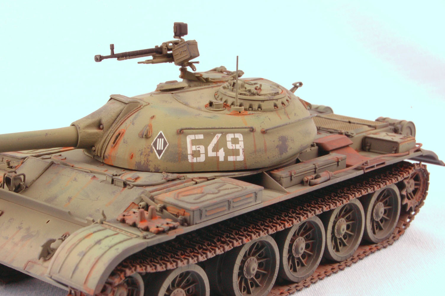
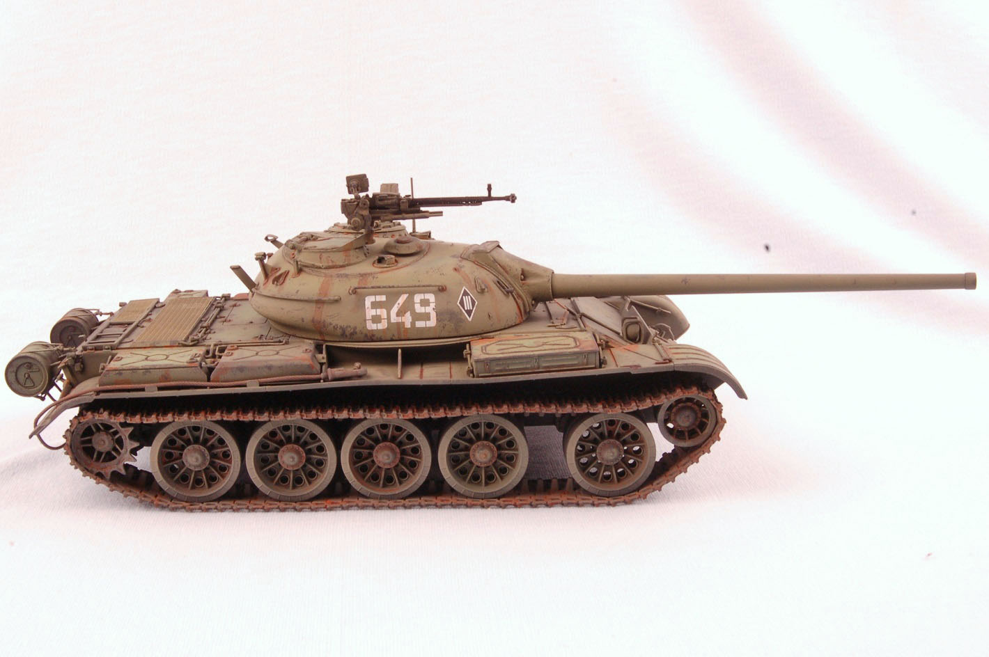
MiniArt provides the modeler with six marking options, all in standard “Soviet Green”, and reading between the lines (because it isn’t clear), being contemporary to the manufacture dates, i.e. the 1950s. I chose vehicle “649”, which also comes with a diamond symbol with a roman numeral “III” in it. Paint colors are called out in the instructions for the following brands: Ammo by Mig, Humbrol, Mr. Color, Testors and Vallejo.
I first airbrushed the kit in my favorite primer, Tamiya rattle can “Fine Surface Primer Light Gray”. This is an acrylic lacquer product and one of the best primers on the market IMHO. I first get a bucket of hot water from the tap and immerse the rattle can in the water for 5 minutes. I remove and dry the can, and then shake the living daylights out of it, to insure a thoroughly mixed can of paint. The hot water heats the paint, thus allowing it to flow better, and by heating the can, I also increase the pressure within the can, thus providing a higher PSI as the paint exits the spray nozzle. This is particularly helpful when the can is less than a quarter full near the end of its life. The Tamiya primer leaves the model with a very smooth surface once fully cured, and doesn’t obscure the fine detail on the kit parts. I then airbrushed Vallejo Black acrylic primer over the entire model.
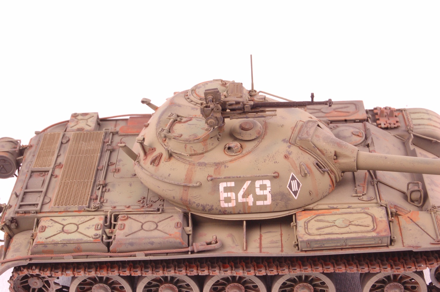
For the Russian Green, I found a mixture online consisting of the following Tamiya acrylic colors: XF-73 Dark Green x 6 parts, XF-49 Khaki x 3 parts, XF-4 Yellow Green x 1 part, plus some X-22 Clear Gloss to give the paint a glossier finish to aid decal adhesion. This was thinned with Tamiya brand acrylic thinner. Once dry to the touch, the original mix was lightened with more XF-4 Yellow Green, and thinned further, and airbrushed onto various panels.
I then found a couple of additional green colors from my various paint stores, and airbrushed these randomly about the place, including various fuel cells, hatches, etc. This to break up the “uniform green” look of the original Tamiya color. This isn’t necessarily accurate, but it certainly is appealing to my eye, in a sort of “Impressionist” way of painting a model kit. Like the original Impressionists from the late 1800s, my intention isn’t to portray life “with complete accuracy”, but rather to give the viewer something interesting to look at. My model, my way of enjoying the hobby, and I have found many people enjoy looking at this way of depicting a vehicle model.
Once the paint had cured for a couple of days, I airbrushed a few thin layers of Tamiya X-22 onto the model, and applied the decals. Four in total: two turret number decals, and two diamond symbols, applied in front of the turret numbers. MiniArt’s decals in this case are perfectly useable. I utilized the Gunze Sanyo setting solution combo (blue top, green top), and after allowing them to dry for 24 hours, applied some light coats of Tamiya X-22 to seal the decals.
After the final clear coat was given a couple of days to cure, I mixed up some dark brown oil paint “wash”, and applied it liberally to the areas of raised detail and in the various recesses. This was allowed to dry for 24 hours before some Q-tips dipped in odorless mineral spirits were used to remove any excess “wash”. The model was then left alone for 72 hours to allow the oil paint wash to set up, before a few light coats of acrylic matt clear were applied. My favorite is AK Interactive’s “Ultra Matt Varnish AK 183”, the “matt-est” matt on the market. I airbrush this without thinning it, straight from the bottle. All my paints are airbrushed utilizing an Iwata HP-C and the paint is sprayed at between 12 and 15PSI depending on the consistency of the paint (if thin for post shading, then 12PSI, but otherwise 15PSI for most applications).
I then took a suitably dark gray color from the Vallejo range of acrylic paints and mixed a couple of drops up with some distilled water and a dab of Vallejo airbrush thinner to break the surface tension. I snipped off a small piece of sponge from a sheet I have of this material and dipped the sponge material in the paint. I then wicked most of the paint off on a paper towel, and then proceeded to dab the paint-covered piece of sponge randomly about the model, “chipping” the Soviet Green paint. I then repeated this process using a dark rust color, only less so. I added to the “chipping” using both these colors, and a fine tipped brush, making scratch marks etc.
Once this was dry, I got out my Lifecolor set of “Liquid Pigments: Rust”, and proceeded to apply dabs of liquid pigment here and there about the model’s surfaces where I thought rust might occur. I paid particular attention to the engine exhaust outlet, as the high temperatures associated with this area of the vehicle tends to blister off the paint on the metal parts fairly quickly. Without paint, these parts are then prone to surface rust.
I took the primed rear deck screens which I had left off the model during earlier assembly work and painted them with Vallejo Olive Drab primer. Why? Simply to add another green hue to the “texture” of the vehicle! The screens were then glued in place using super thin cyano glue utilizing a Glue Looper. If you haven’t tried the Glue Looper for applying runny super glue, you don’t know what you are missing! Google it, buy it!
Regarding the commander’s turret AA gun, this was sprayed independently of the turret and hull with Vallejo black primer. Once fully cured, I hand painted all but the barrel with Vallejo Olive Drab primer, the same color used for the rear deck screens. I then “chipped” this paint utilizing the gray paint method mentioned earlier.
The tracks were hand painted utilizing Vallejo “Track Color”, a dull rusty brown color. Various shades from the Lifecolor Liquid Pigments: Rust set were utilized as “washes” for the tracks.
I then airbrushed some Tamiya XF-57 Buff over the running gear and parts of the lower hull as “road dust”. A very light coating was applied to the entire vehicle.
The AA gun was attached to the turret, and the turret to the hull, and the whole model was given a few light coats of AK Interactive Ultra Matt Varnish to seal the whole deal.
In Conclusion
While I very much enjoyed the challenge of the earlier MiniArt T-54-1 Model 1947 with its full interior, it was a very time-consuming build. For those with less time, I believe these “exterior only” kits are a great idea. You get fabulous detail in all the areas that you can actually see following completion. If you are looking for a great T-54 kit, you need to look no further than the MiniArt range. This kit is HIGHLY recommended for its superbly detailed parts, and excellent parts fit. My sincere thanks to MiniArt for allowing IPMS USA to review this wonderful model kit.


Comments
Add new comment
This site is protected by reCAPTCHA and the Google Privacy Policy and Terms of Service apply.
Similar Reviews