
T-55 Mod. 1963 Interior Kit, Part 1
Introduction
This is part 1 of the review of MiniArt’s T-55 Mod. 1963 Interior Kit. Part 2 will complete the assembly of the turret, tracks, fenders, and the remainder of the kit.
This kit is the first of MiniArt’s T-55 variants and follows their earlier series of T-44/54 Russian tank kits. Following their previous versions, this kit is first released with full interior detailing. MiniArt has also announced a soon to be released IDF Tiran version of the T-55, and a T-55A Late Mod. 1965.
With over 1200 parts, this is an extremely well-detailed kit that is best suited for patient, experienced modelers. MiniArt provides full interior details of the hull, turret, and engine. The drivers' compartment provides some detail, but not as complex as the other areas. There is no detail in the rear compartment for the transmission, oil cooler, fan, etc. There is also no provision for the main fuel tank at the front of the hull. Otherwise, this tank is packed full of extreme detail!
The fit of the parts is exceptional! With just a little bit of fudging, the complex side panels fit to the lower Hall almost perfectly. The upper hull plates for the engine cover and transmission compartment covers all fit extremely well to the side panels. The front glacis plate fits so perfectly that glue is not necessary.
With the fantastic interior detail on this kit. I decided to use cut-outs of the hull decks, fenders, and turret to display the otherwise hidden details. I added some detail in the driver’s compartment, front fuel tanks, and transmission compartment to fill in some gaps in the kit details.
Kit features described by MiniArt (with my comments):
- Workable torsion bars (with careful gluing the suspension will work)
- V-55 engine included (although no transmission, oil cooler, or fan are included)
- Fully detailed fighting compartment interior (fantastic detail!)
- Driver compartment interior accurately represented (but with minimal detail)
- All hatches can be posed open
- Individual track links
Build up options:
- The kit can be assembled with or without fitting for mine roller system (fittings only, no mine roller).
- Fitting options of deep wading equipment. (in closed position only)
- 2 types of fuel tanks.
- 2 types of toolboxes.
- 2 options of anti-rain cover for the driver.
- The kit can be build up with or without gun mantlet cover.
- 12 variants of painting and marking
- 51st Infantry Division of the army of the Republic of Iraq, March 2003.
- Vietnamese People’s Army, 2000’s.
- Captured T-55 during the “six-day war” as part of the IDF, 1968
- Army of Egypt, 1973-1974 years
- Syrian Army, “Yom Kippur War”, 1973
- Army of the Republic of Cuba, 70’s
- Finnish Defense Forces, 1973
- Army of Ethiopia, “Ogaden War”, 1977
- Army of the Republic of Iraq, “War in the Persian Gulf”, 1991
- Parade in the honor of the 50th anniversary of the October Revolution, 1967.
- 24th Motorized Rifle Division of the Soviet Army, Kyiev, 1967
- Soviet Army, Operation “Danube”, Prague, 1968
Kit contents:
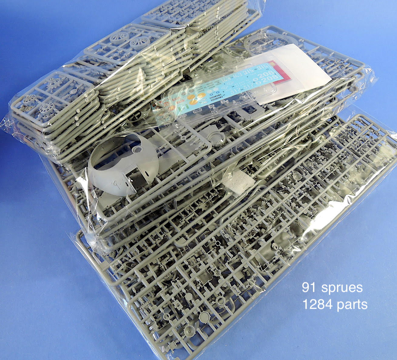
- Total details 1284
- 1091 plastic parts
- 167 photoetched parts
- 26 clear plastic parts
The kit comes in an oversized 9 1/2 x 15 x 4 box laden with 91 sprues in 3 plastic bags, plus the instruction booklet. Inside one of the bags is a smaller bag containing the clear plastic parts, decal sheets, and two photoetch frets. Examining the sprues reveals many, many, very small parts, indicating the fantastic detail provided with this kit. This is not a quick build.
The instructions are an 8 1/2 x 12, 32-page stapled booklet with 104 assembly steps. The instructions include paint numbers from Vallejo, Humbrol, Mr. Color, Testors, AMMO MIG, and generic color names. Detail color call-outs are included in each of the assembly steps. Color paint and marking illustrations are provided for 12 different options in color profile drawings.
Diagrams of each of the plastic sprues, photo etch frets, clear parts and decal sheet helps to identify the location of parts of a large number of sprues. Labeling or indexing helps locate the correct sprue during assembly, as many steps require parts from multiple sprues.
The plastic is relatively soft, which helps with the clean-up and handling of the long, thin, parts. MiniArt uses multiple sprue connections on each part to help with the very fine detail but adds to the clean-up challenges. Examine the parts before removing from the sprues, as some of the connectors are at the end of locating pins. There is some very minor flash on a few parts. Check carefully as MiniArt has cleverly added weld beads on the edges of parts that may appear to be flash.
Assembly
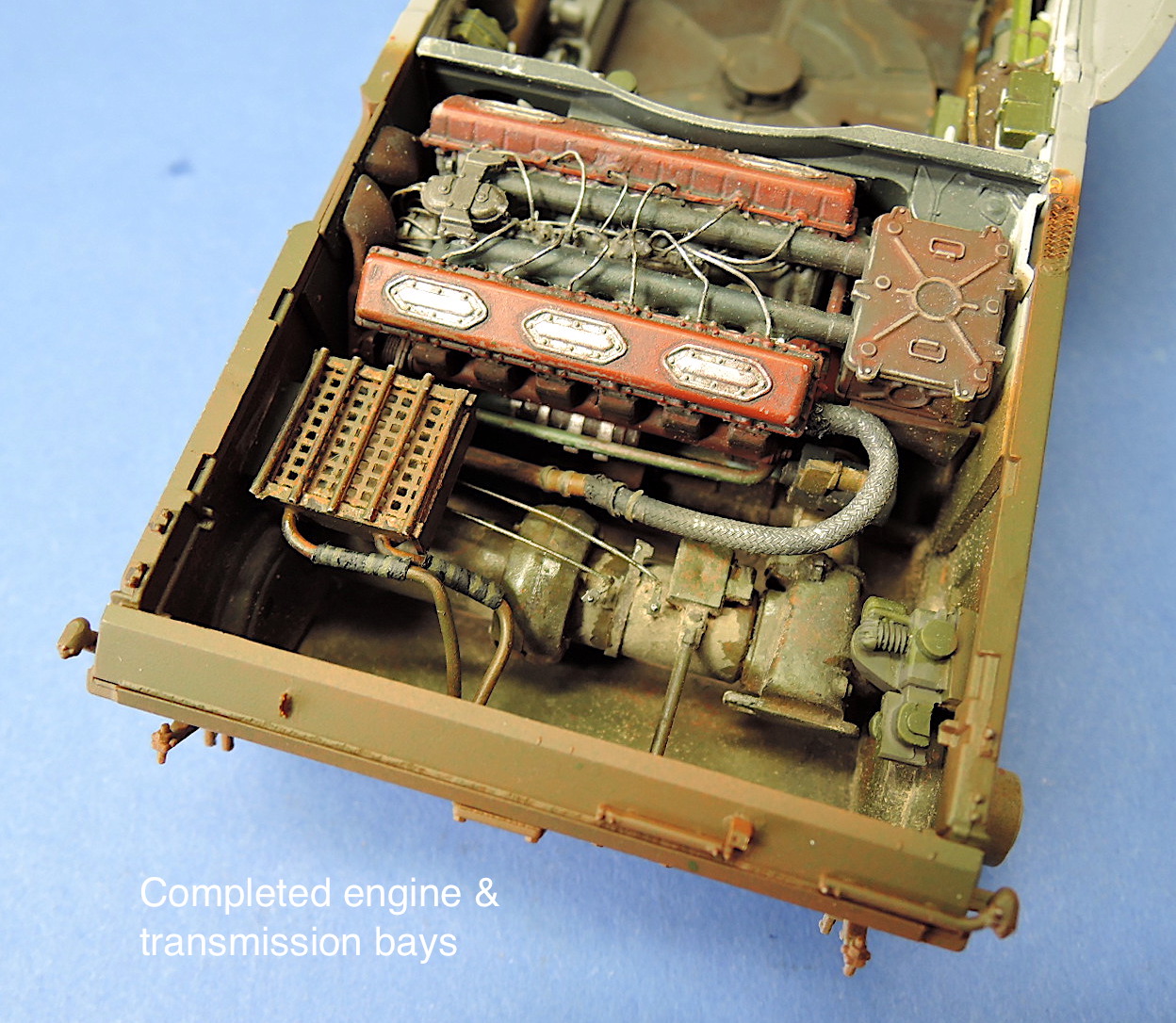
Assembly begins with the construction of the engine in steps 1 through 8. The engine assembly contains 33 parts. There are some provisions to add ignition wiring and fuel piping in parts Gc22, and the Gc3 cylinder heads, so I added wire based on reference photos. Detail painting instructions are included in the assembly steps.
Suspension Assembly
The lower hull assembly begins in steps 9 and 10 with the installation of the mounts for the torsion bars and swingarms. Take time with this step, and with patience, the swingarms and torsion bars will be workable. The mounts for the torsion bars fit tightly into place and I aligned them with the inside of the lower hull, trying to keep the exterior in line. Dry fit the hull side, parts A4 and A5, to check the fit of the torsion bar mounts. The torsion bar and swingarm assemblies in step 10 require some careful gluing but will build up to a workable suspension. The torsion bars need to extend all the way through the opposite bracket for the swingarms to fit tight against the hull. I left the link, part Ho1, unglued to the pin Ho4, hoping that it will stay in place without gluing that might lock the pin in place. I left the torsion bars unglued until I can set the correct angle for the swingarms. There is also an option to lock the swings arm swingarms in place using the short bar Tc8.
Hull Assembly
Steps 11, 12 and 13 install the floor platforms in the bottom of the hull, along with the driver control levers. These steps also install the housings over the idler arms. Careful gluing of the housings to avoid touching the idler arms will aid the workable suspension. At this point, I also applied a touch of liquid cement to the opposite ends of the torsion bars to fix them in place. Once dry, the torsion arms allowed the idler arms to rotate, but only a couple returned to level as well as I had hoped.
More detail in the driver’s area and the ammo shell “wet storage/fuel tank” are added in steps 14 through 17. The wet storage rack is not assembled as a tank but ends up looking like one, except without the top covers. I was going to expose this part of the interior so I added tops to the tanks. The front triangular fuel tank is not included with the kit.
The ammo provided with the kit appears to be a mix of OF-412, BR-412D, and BR-412B shells.
The complexity of the interior is starting to show with lots of parts in very tight spaces, although everything fits very well. The drivers' instrument panel is installed in step 16, but there are no decals for the gauges or painting instructions provided. The instrument panel is called out to be painted black, but reference photos show it to be a silver color and black gauges with white lettering. I added the gauge cases and wiring on the rear of the instrument panel as I plan to expose the driver’s compartment.
Side Panels
Steps 18 through 24 continue assembly of the interior side panels of the hull tub. MiniArt separates the side panels from the bottom of the tub, which makes for easier installation of the numerous details on the sides, but creates some complexity in assembling the side panels to the tub floor. I painted the parts as they were assembled. It is very important to test fit the side panels to the floor of the tub as some adjustments were necessary. Best to get this done before painting the interior of the panels. Steps 18 and 21 show installation of lights to the outside front and back of the hull side panels. These can be installed much later after all the hull top panels are assembled to avoid breaking them off during assembly.
Steps 25 through 30 install the engine mount, more ammunition shells, pump, and additional equipment on the interior of the hull. No real fit issues here but lots of patience to get all of the small parts put together and the shells correctly anchored. Step 29 assembles what appears to be another periscope, consisting of many small pieces, and the fit is not very precise. It would’ve been better to mold these parts combined in fewer parts.
Step 31 installs the right side of the lower hull and firewall to the engine compartment. Some minor trimming and clamping are required for the side panel, but it eventually fits well.
Step 34 assembles the air filter and piping to the engine. The exhaust piping, parts Gc13 and Gc14 didn’t seem to be wide enough to fit around the engine without bending.
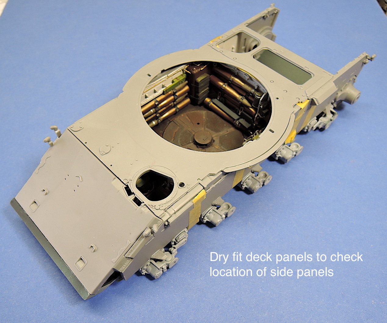
The engine and left side panel of the hull are installed in step 35, again with some minor trimming of the side panel. I dry fit the deck panels to make sure the side panels were correctly spaced and in the right location. The panels all fit nicely.
Unfortunately, MiniArt does not provide any detail in the rear hull compartment for the transmission, oil cooler, compressor, fan, etc. I cobbled together some spare parts to provide some detail in this compartment. Both Verlinden and CMK make add-on details for the transmission, although intended for the Tamiya T-55 kit.
The front glacis panel is installed in step 36. The headlight, subassembly A, has a very delicate frame. I assembled the frame in place on the hull panel to assist with the assembly. The frame broke several times during later assembly steps, and it would be better to install the headlights much later in the assembly process. There are options for a clear or fresnel lens on the headlight. The step also has optional parts for the mine roller system. Part B11 or Pb1 provide alternates for a wood or metal board on the front of the hull.
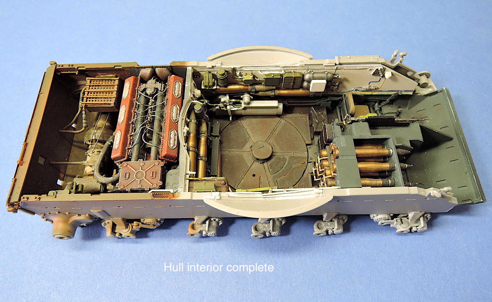
The first 35 steps completed the assembly of the lower hull and all of its detail parts. The lower hull ends up being an impressive space with all of the added interior detail. Patience and careful fitting of the parts will result in an impressive assembly. All of the many detail parts fit very nicely. Still to go is the equally detailed interior of the turret.
Wheel & Suspension Assembly
Assembly of the road wheels and suspension is in steps 38 through 44. For the road wheels, note the tiny locating pins on all of the parts for correct orientation of the wheel halves. In step 40, I found a defect in the castings for the rear sprocket wheels, parts Ta1 and Ta2. The center hole was not drilled and there was considerable flash deforming the center of the wheels. I emailed Miniart and they quickly dispatched replacement parts. I held off installing the wheels until the replacement parts arrived. Very good customer service by MiniArt!
Rear Deck Panels
The rear deck panels for the hull are assembled and installed in steps 45 through 51. The louver panels over the engine and transmission bays are nicely detailed parts that assemble well. Photoetch screens are provided as well as some microscopic clips on the louver panel. Louvered panels over the fan and radiator are assembled in step 51 with individual photoetch slats for the louvers. I found it very difficult to get the PE slats located properly due to the small notches for their location. Be careful trimming the edges of these slats to maintain the notches on the ends of the slats.
Summary
This Part 1 of the T-55 review covers the lower hull, suspension, and interior detail. The second part of the review will include the incredibly detailed turret, track, fenders, and final assembly of the kit.
This is an excellent, fantastically detailed model kit. MiniArt has produced a kit with the finest detail and best-fitting parts that I’ve experienced! This certainly is a high standard for model kits!
All this detail comes at a price though. Lots of experience working with small (i.e. microscopic), and huge numbers of parts is necessary to complete this model. Patience and lots of time will be necessary to build this kit. So far, I’ve spent about 160 hours on assembly and finishing this example, and I’m only about halfway complete. In spite of the complexities, I’ve enjoyed this build immensely.
Many thanks to MiniArt for producing this fantastic kit and providing the review sample to IPMS! Thanks also to Ben Mirson at IPMS for helping with my questions.


Paint and decal placement guide
Sprues

Test fit of rear deck lid
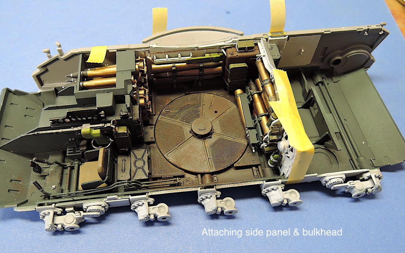
Attaching the side panel
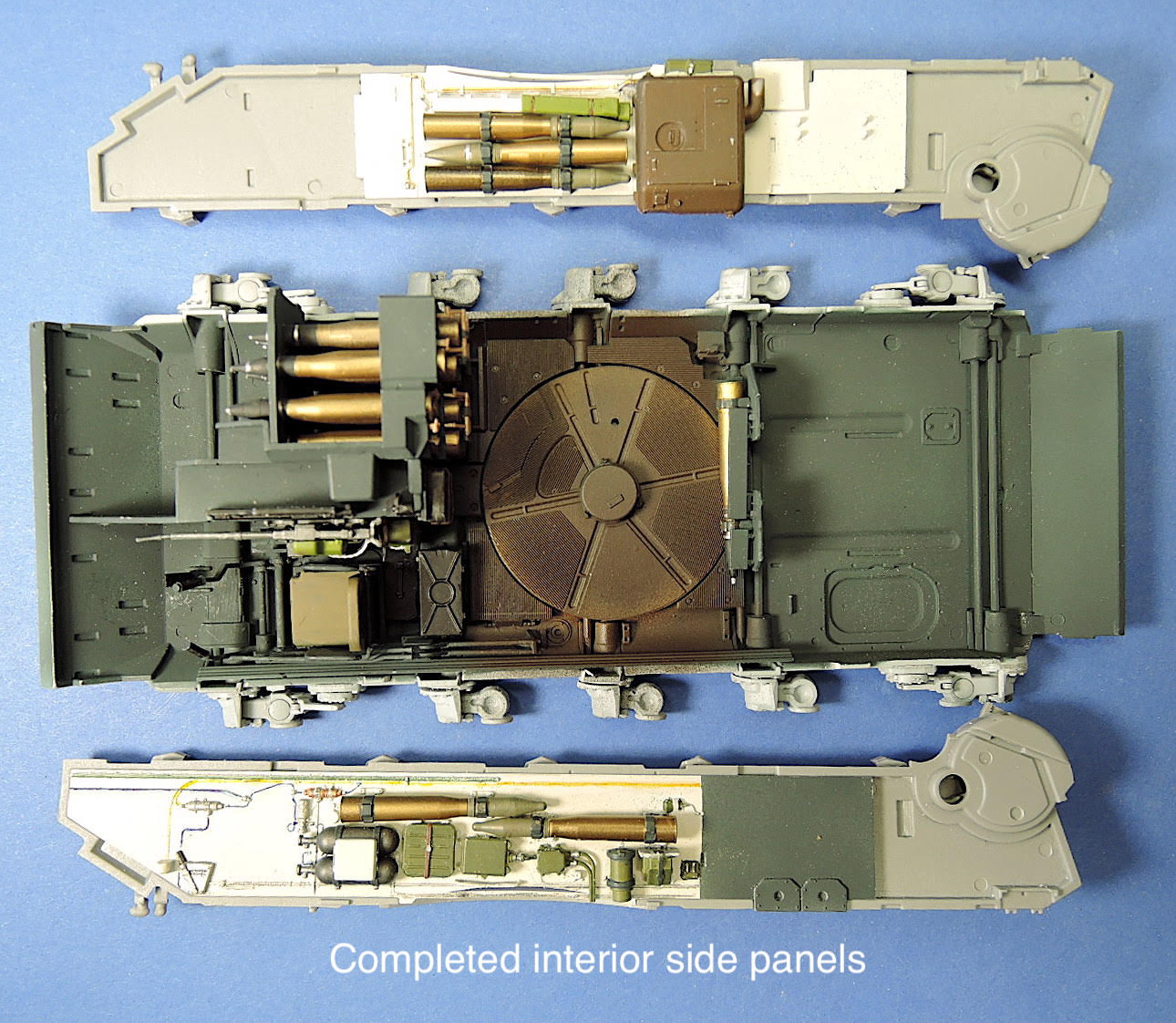
Completed interior panels

Tiny Photoetch Part

Anchoring the torsion bar end
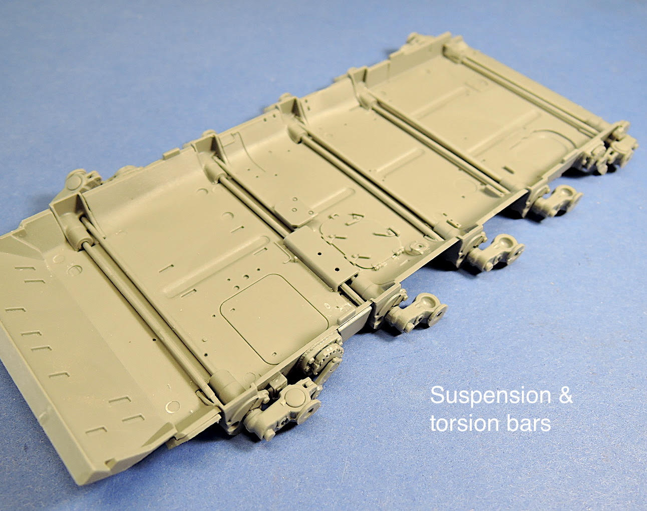
Suspension and torsion bars
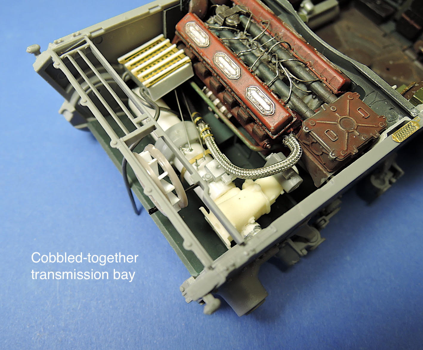
Transmission Bay
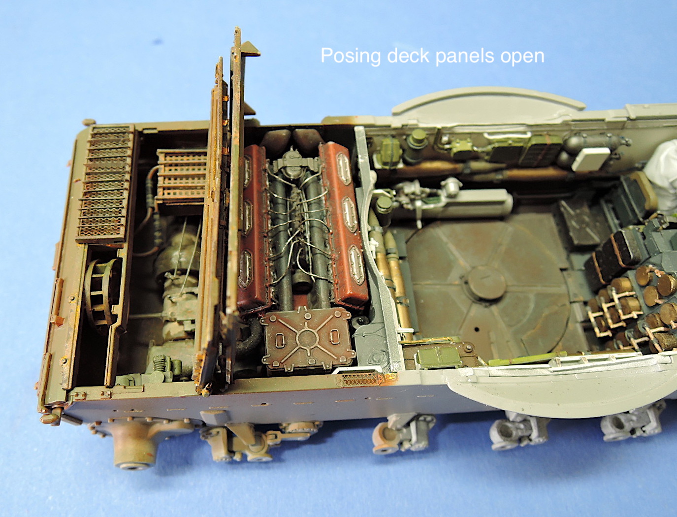
Posing the deck panels open
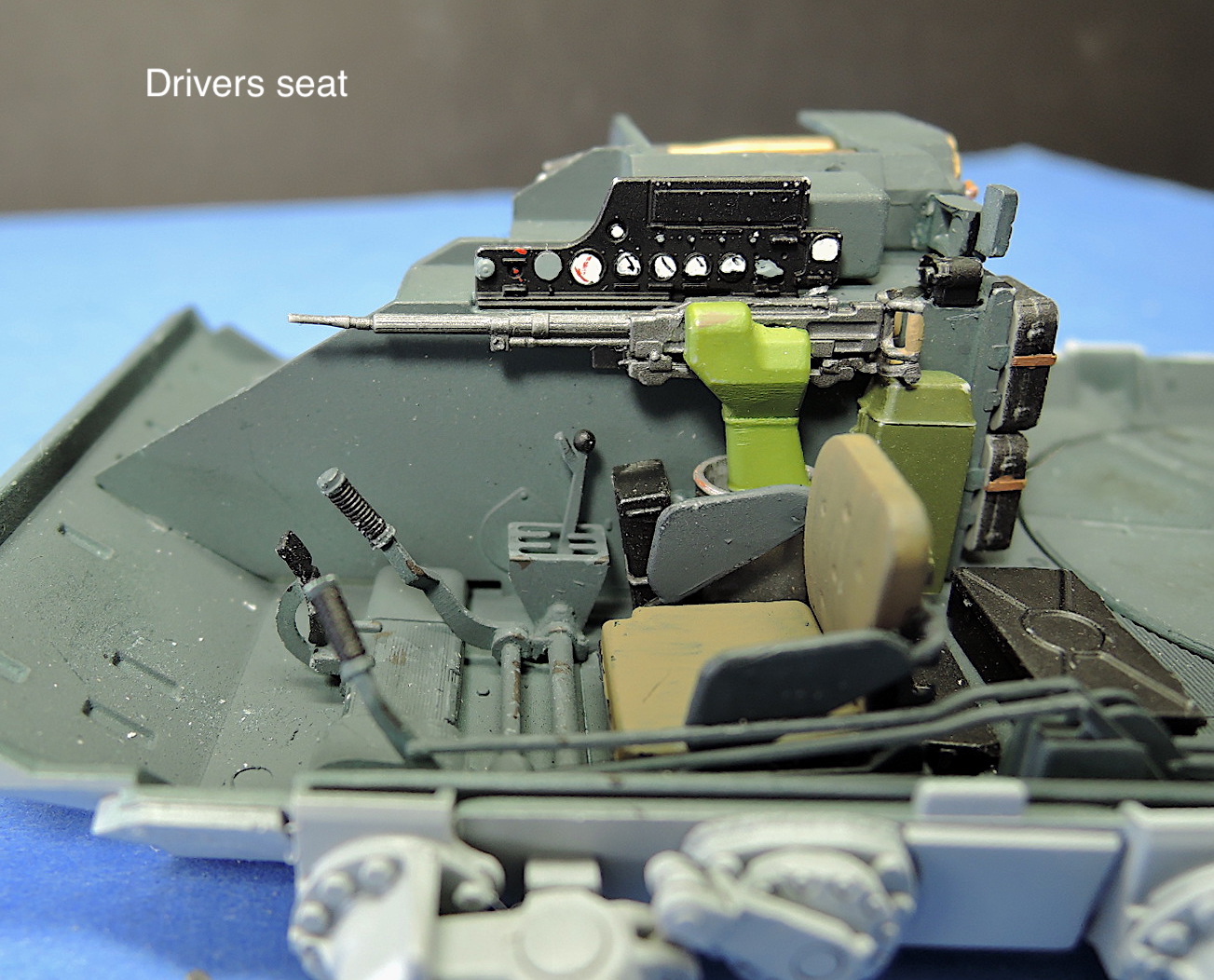
Drivers seat
Engine area
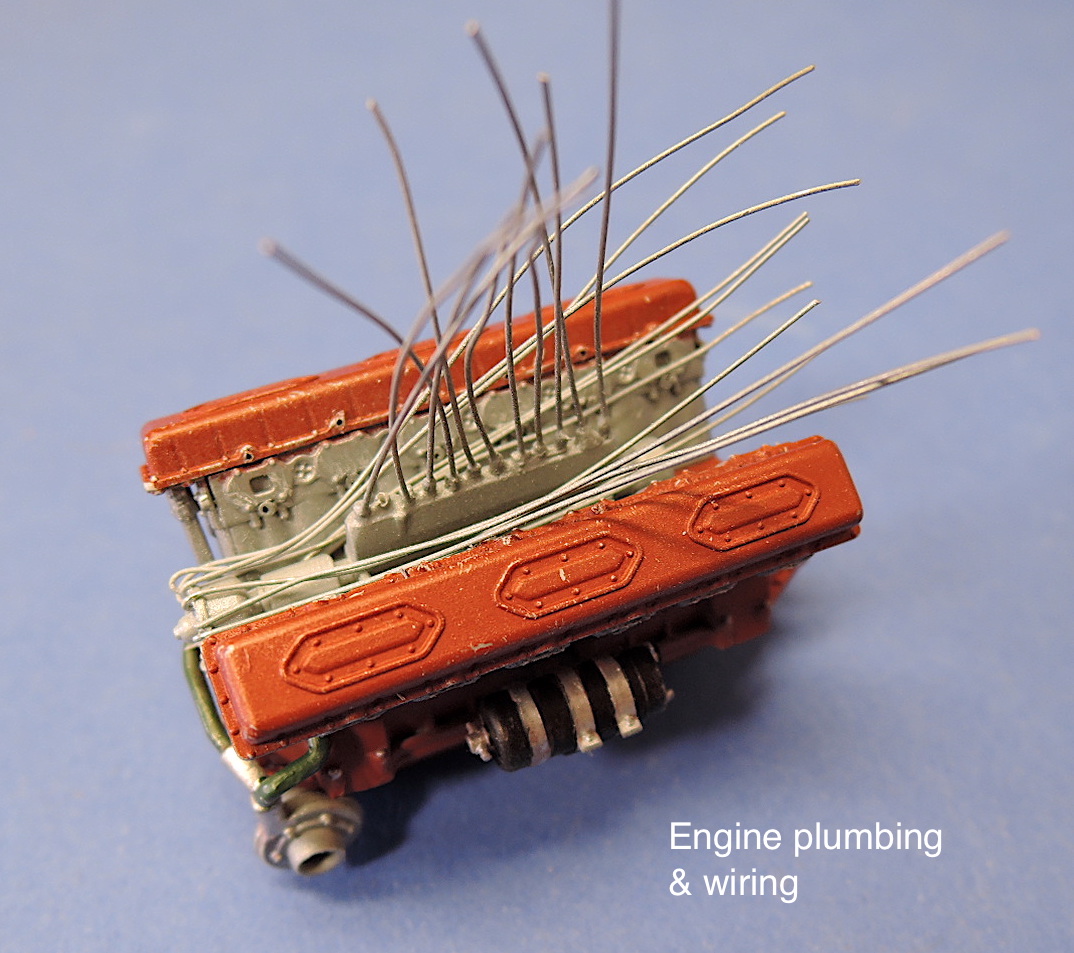
Engine detailing
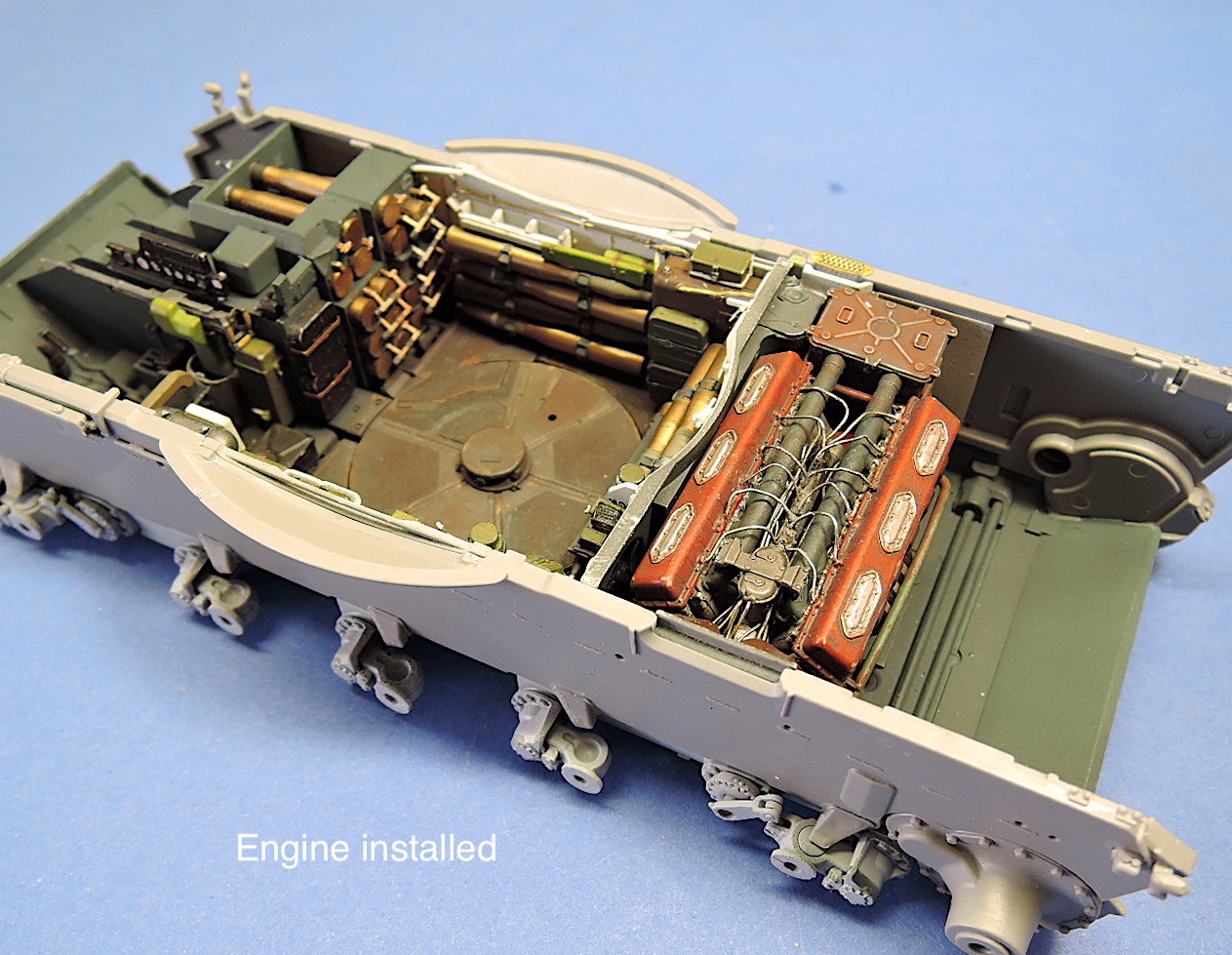
Engine installed
Hull test fit
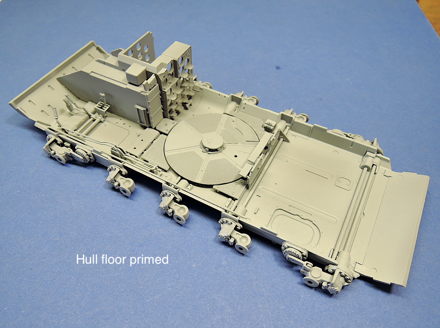
Hull floor
Comments
Add new comment
This site is protected by reCAPTCHA and the Google Privacy Policy and Terms of Service apply.
Similar Reviews