
T-55 Mod. 1963 Interior Kit, Part 2
Introduction
This is part 2 of the review of MiniArt’s T-55 Mod. 1963 Interior Kit, including assembly of the turret, tracks, fenders, and the remainder of the kit. Part 1 of this review included the engine, suspension, hull assembly, hull side panels, and rear deck panels.
This kit is one of MiniArt’s T-55 variants and follows their earlier series of T-44/54 Russian tank kits. Following their previous versions, this kit is first released with full interior detailing. MiniArt has also announced an IDF Tiran version of the T-55, and a T-55A Late Mod. 1965.
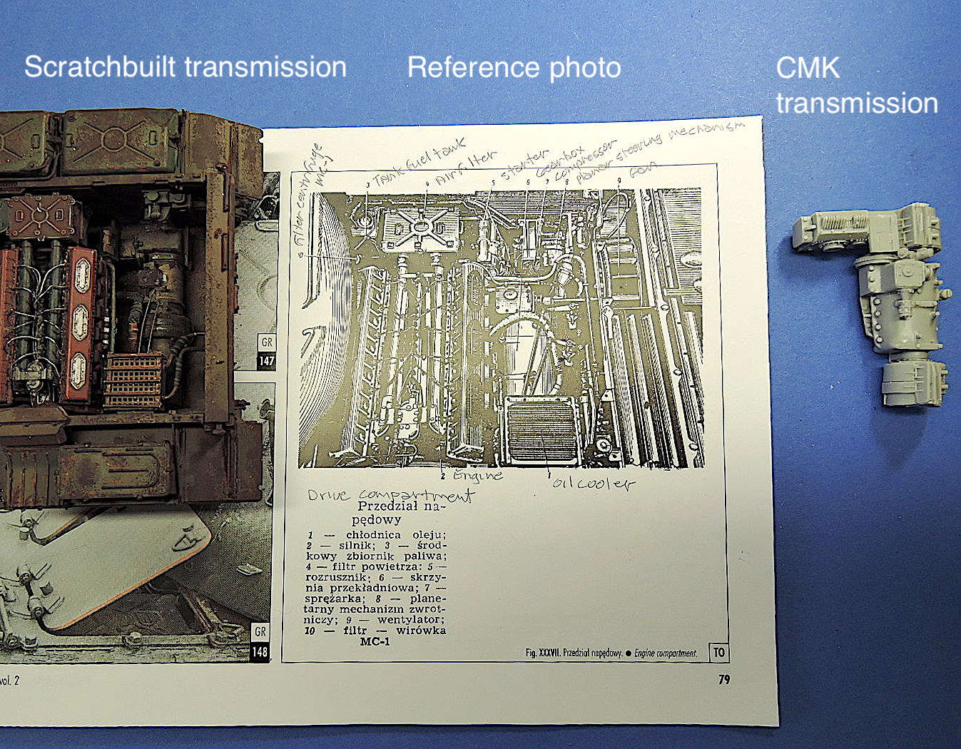
With over 1200 parts, this is an extremely well-detailed kit that is best suited for patient, experienced modelers. MiniArt provides full interior details of the hull, turret, and engine. The drivers compartment provides some detail, but not as complex as the other areas. There is no detail in the rear compartment for the transmission, oil cooler, fan, etc. There is also no provision for the main fuel tank at the front of the hull. Otherwise this tank is packed full of extreme detail! Comparison to reference photos show the kit to be very accurate.
The fit of the parts is exceptional! With just a little bit of fudging, the fenders fit to the lower hull almost perfectly. MiniArt includes piping for the exterior fuel tanks that is nicely scaled and fits perfectly. The turret interior is packed full of details that also fit nicely. The parts of the turret and base fit tightly and allow the turret to rotate.
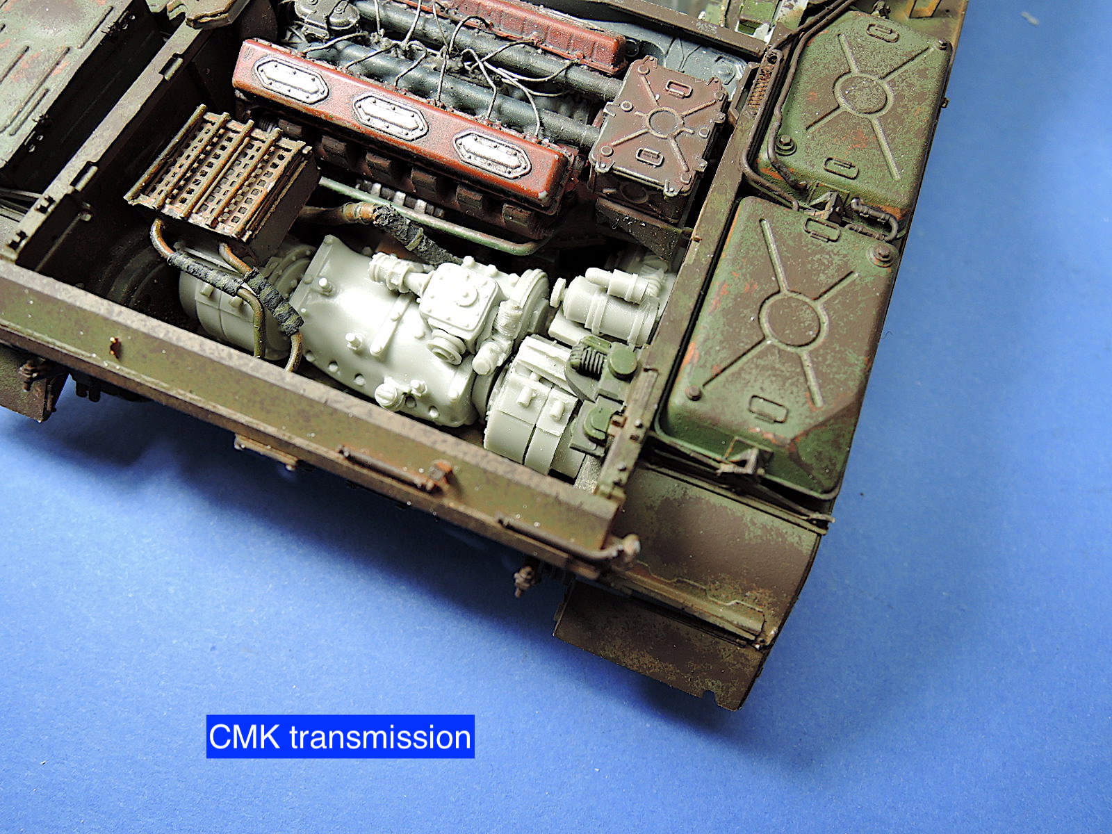
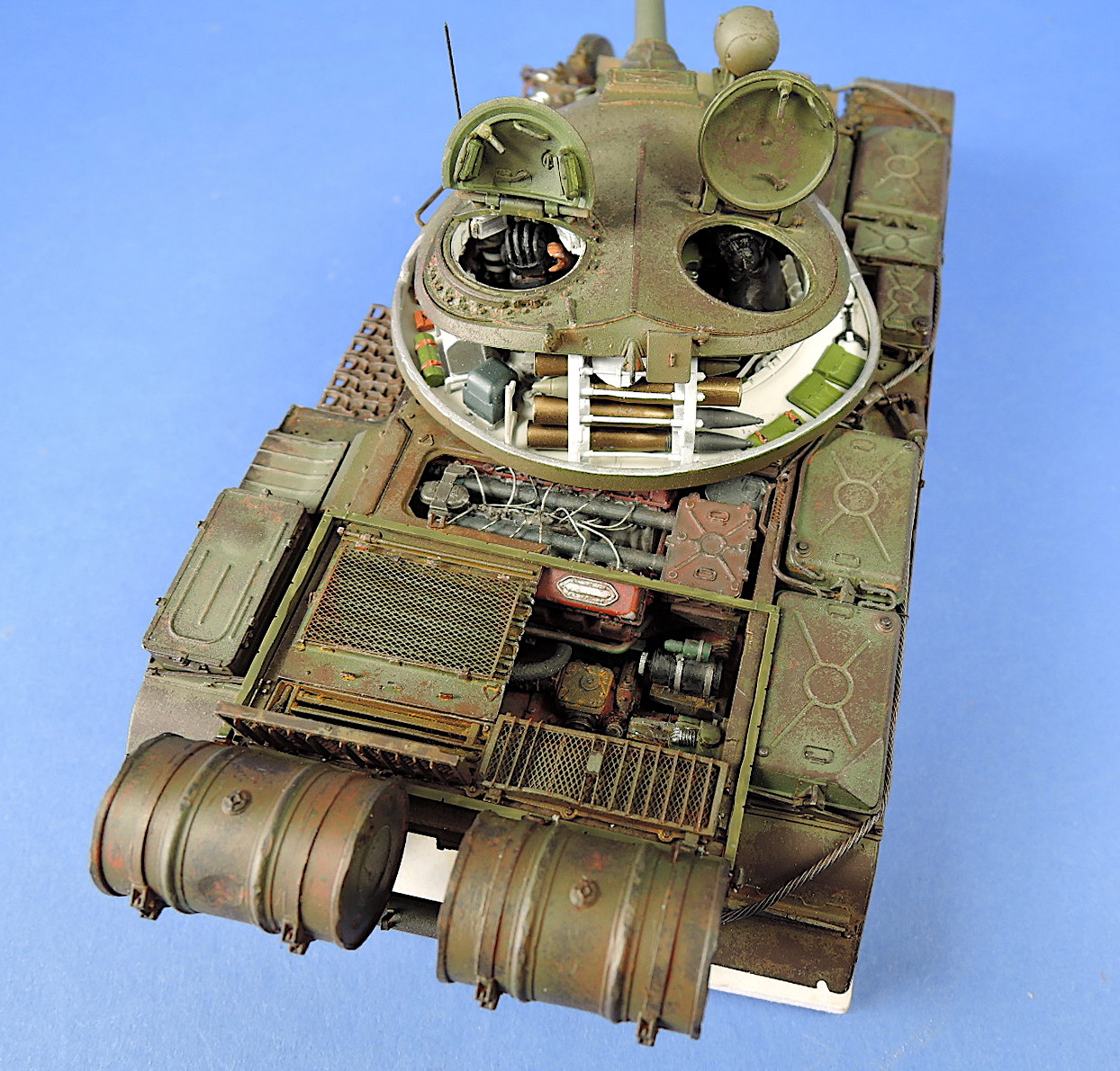
With the fantastic interior detail on this kit, I decided to use cut-outs of the hull decks, fenders, and turret to display the otherwise hidden details. I initially scratchbuilt the transmission, fan and oil cooler in the rear hull compartment, as these are not provided by MiniArt. I was not satisfied with the result and replaced the transmission with the CMK kit intended for the Tamiya T-55. The parts fit OK with slight modification and look much better.
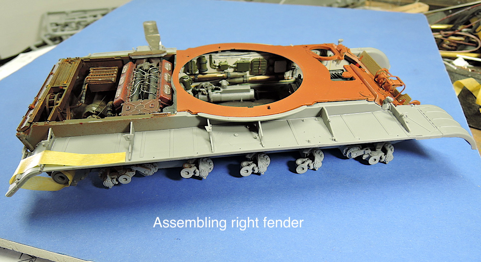
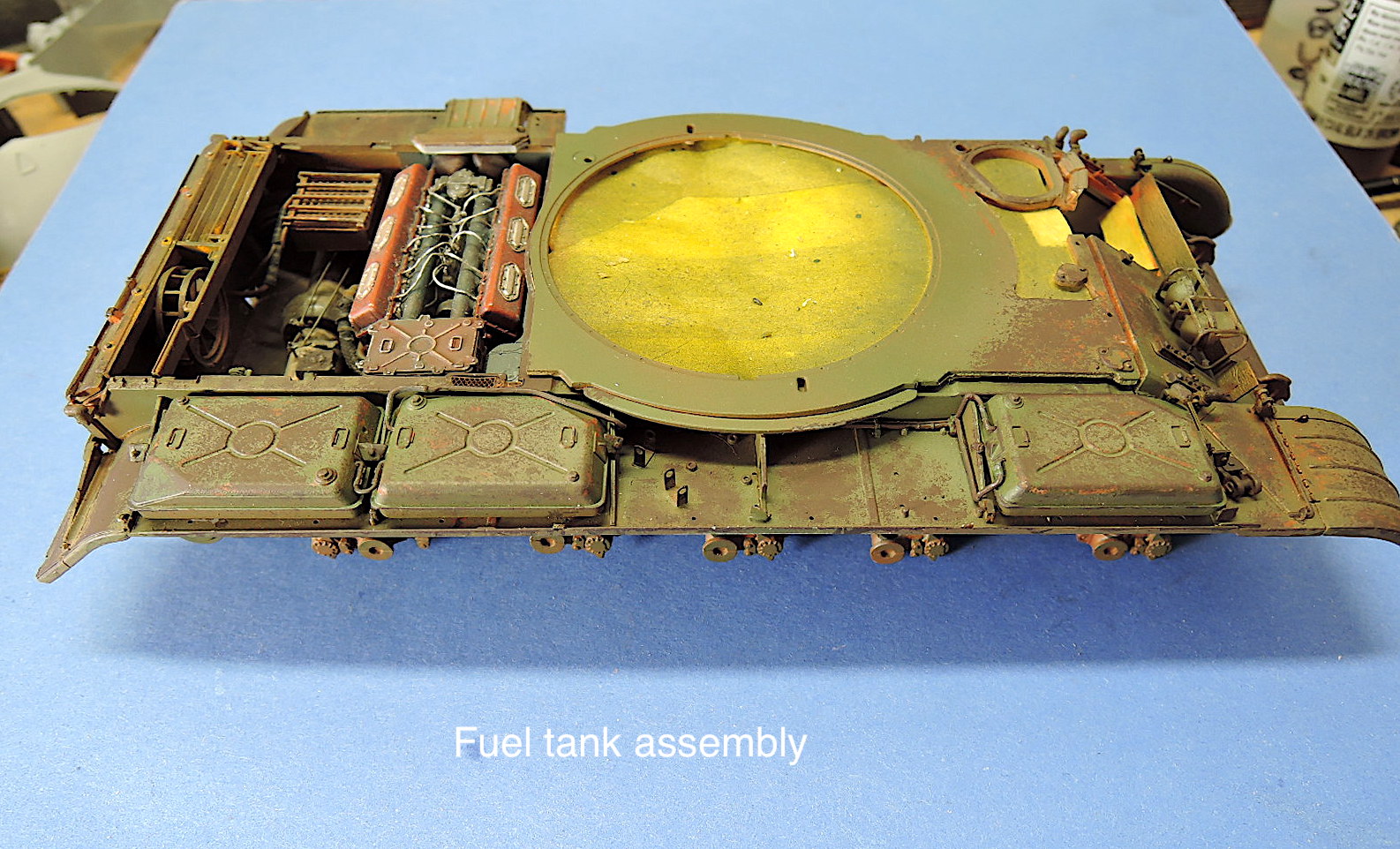
The fenders and fuel tanks are assembled and installed in steps 52 through 56. The instructions show installing the tanks to the fenders prior to installing the fenders to the hull sides, but I found it easier to install the fenders first then place the fuel tanks. There are different fuel tank options for early or late type vehicles. MiniArt also provides the fuel piping for the tanks.
A braided wire tow cable is provided with the kit and shown to be installed in step 58.
The rear fuel drums, deep wading equipment, and optional ditching log are installed in steps 60 to 64.
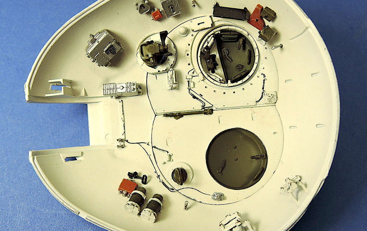
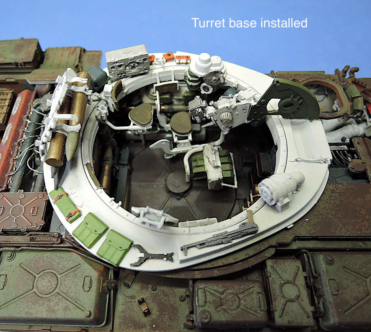
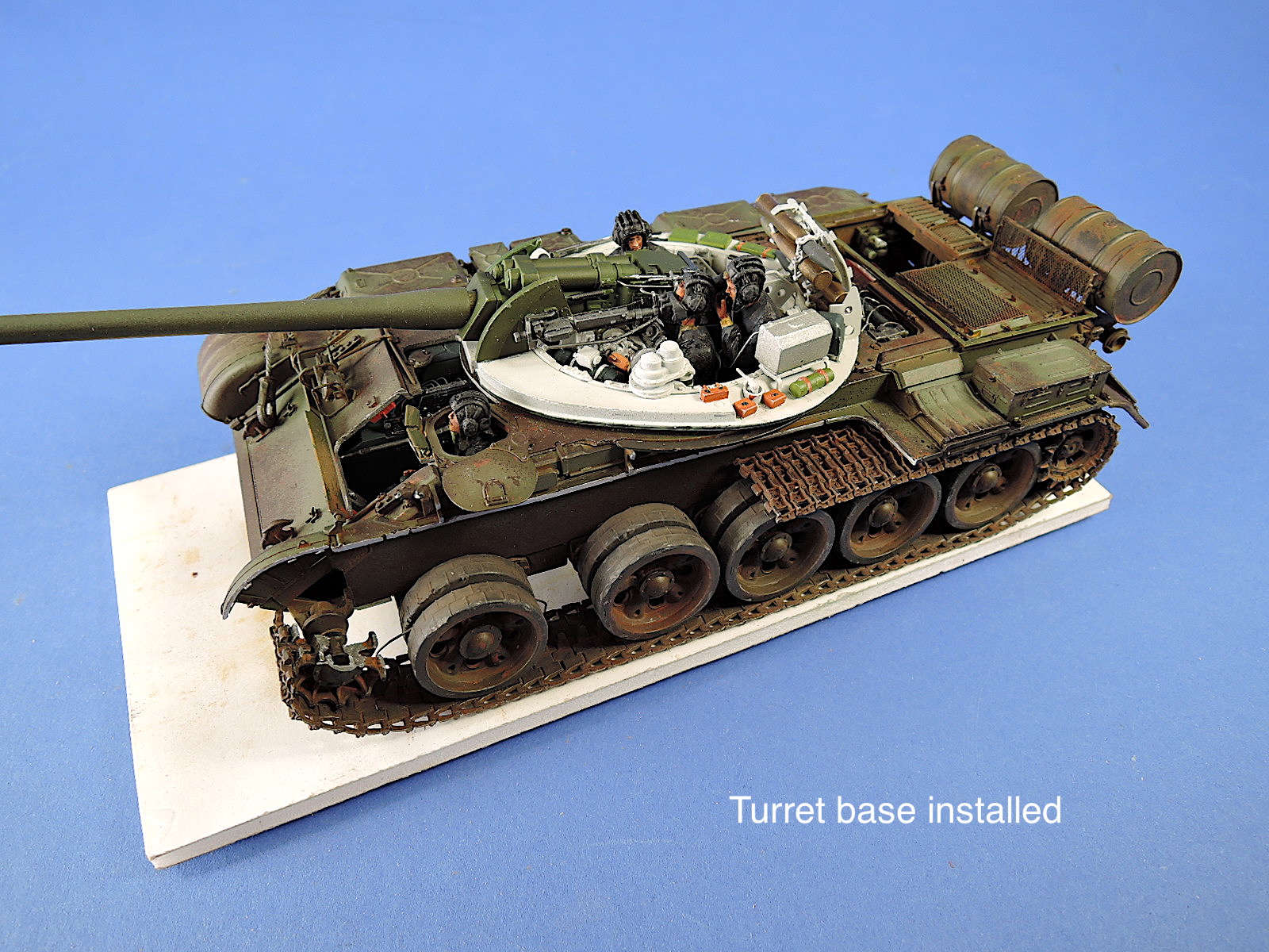
Assembly of the large number of details in the confined space of the turret begins on page 21 of the instructions and step 66. Assembly begins with the lower mounting plate for the turret, which allows it to rotate, although the locking pins are a loose connection and can pop out. There are two mounting positions for the loader’s seat, but this is not noted in the instructions. The seat can also be installed down or folded up. Steps 68-71 install many pieces of equipment to the turret base ring. The rear storage rack for shells is a delicate assembly that I installed to the turret ring right away to help hold it together, but waited until later to install the shells.
MiniArt does not provide labels and gauge faces for the interior, such as the position indicator for the turret rotating mechanism in subassembly A in step 67, although this would disappear like many other labels hidden behind other details in the turret.
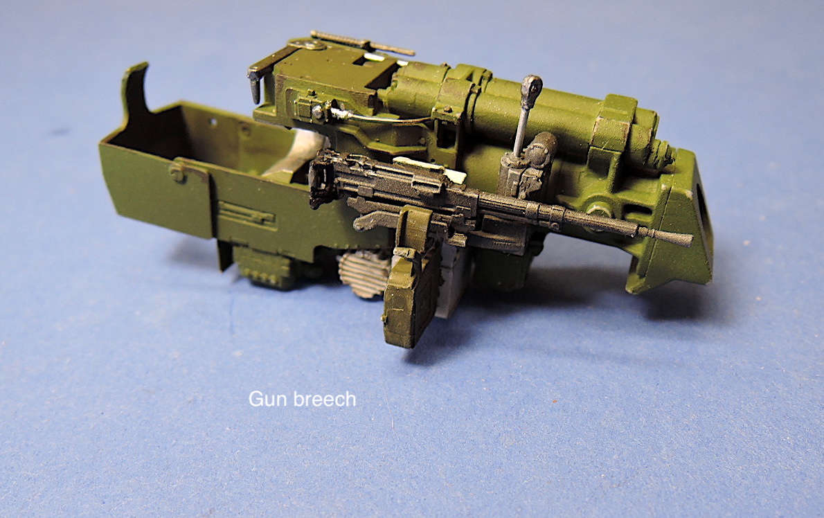
Step 72 and through 74 assemble the breech for the main gun. MiniArt shows installation of a shell in the breech, although I removed it after aligning the part. There are missing labels on the sides of the breech also. I applied some generic labels.
The axial machine gun assembled in step 75 through 76 has very nice detail.
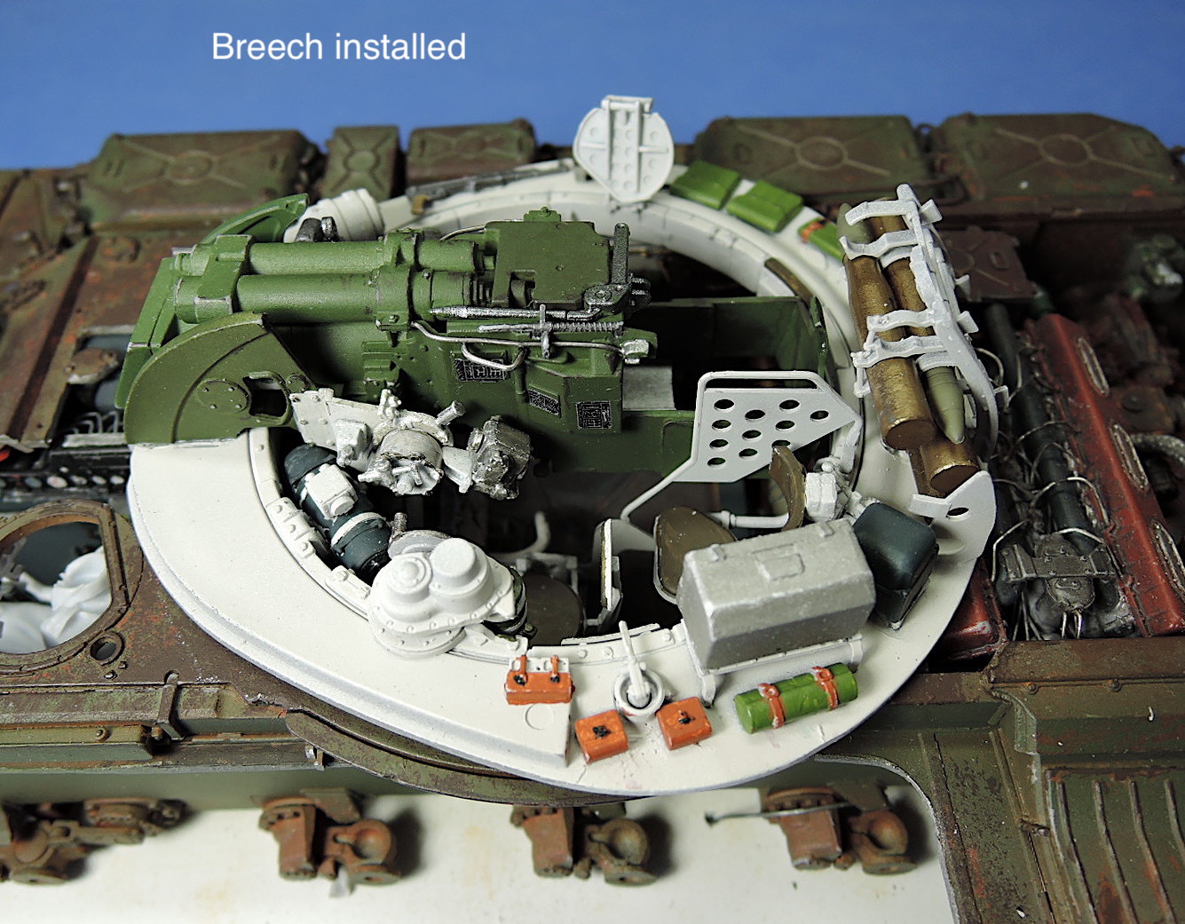
The gunner’s seat is installed in steps 79 through 82. I plan on using crew figures inside the turret, and the scale thickness of the driver’s seat bracket will be hard-pressed to support the figure. The gun breech, gunner’s seat, shell storage rack, and gunsight are installed in steps 83 through 85. After gluing the breech brackets in place, I was still able to remove and replace the gun breech several times during assembly for painting and installing other details. The gun can elevate slightly, although installation of part Gb6 in step 85 will fix the angle of the gun in place. Step 85 shows installation of a rod, part Gb17, installed at one end but does not show the connection for the opposite end.
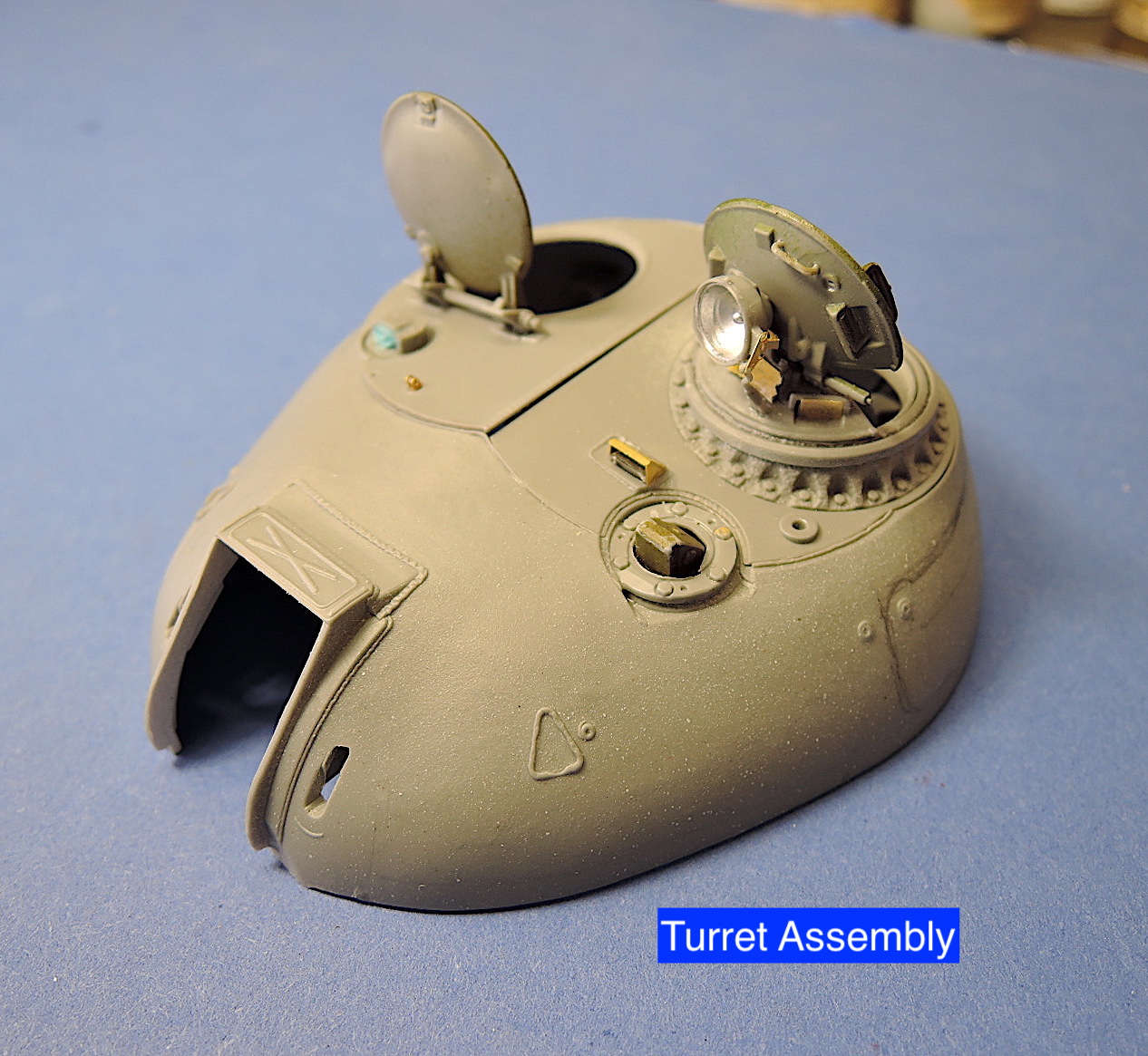
Step 86 thru 88 install many more details for the equipment on the inside of the turret. Many of these detail pieces have connectors that create possibilities to add additional wiring. The exterior of the turret has nicely molded texture for the casting. The top ring for the commander’s periscope showing in step 87 is part Da4 but is not labeled.
I cut open a large portion on the rear and sides of the turret to expose the interior detail. I also left the top plates for the turret hatches unglued to allow removal for viewing the interior.
The commander’s and loader’s hatches are detailed in steps 91 through 94. The hatches and the top plates are nicely molded with excellent detail and fit very well. The hatches are not hinged but can be glued in the open or closed position. Options are provided for the night vision system to be displayed either in the daytime or nighttime operation mode. The lenses for the night time system have a slight bluish-gray tint in reference photos but the color is not called out by MiniArt.
The main searchlight installed in step 98 also has a clear plastic lens or a solid cover option. MiniArt even provides a separate bulb inside the light!
Both solid and canvas-covered options for the gun mantlet cover are provided for the tank. Photoetch pieces are provided for the bolt strips around the mantlet. The side strips are incorrectly shown on the side of the turret opening but should be on the face of the opening.
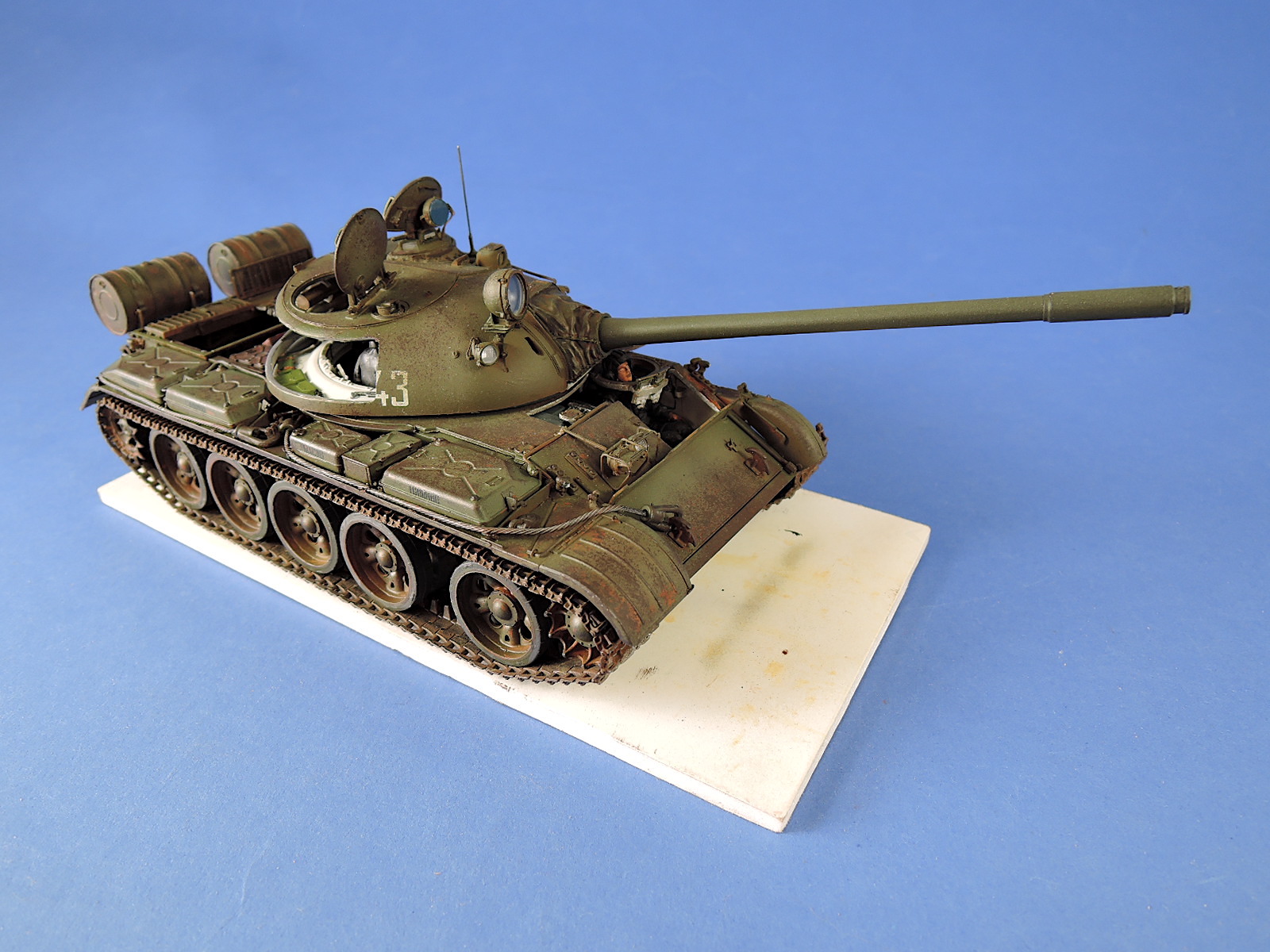
The detailed turret top is finally attached to its base plate in step 99. It’s a tight fit & needed some scraping with an X-Acto blade to fit properly. The gun barrel is also installed. The barrel is nice and straight and includes rifling in the barrel end. The turret gets installed to the hull in the last step, 104. Tabs allow the turret to turn, but they are small and the turret can pop off.
There are two options for the shield over the driver’s hatch, although the marking options only show them in the stored position on the rear of the turret.
I generally followed the paint colors called out in the instructions except for a few differences in the references I was using. The tank exterior is weathered to represent heavy use and some rusting. Main paint colors & finishes used:
- Interior - Tamiya White Primer, AV Model Color Silver Grey, Tamiya Field Blue.
- Engine - AV Model Color Cavalry Brown, German Grey.
- Exterior - Alclad Gray Primer, AV Model Air Camouflage Black Brown base chipping coat, AK Worn Effects chipping, AV Model Air Russian Green, AV Panzer Aces Dark Rust applied with sponge.
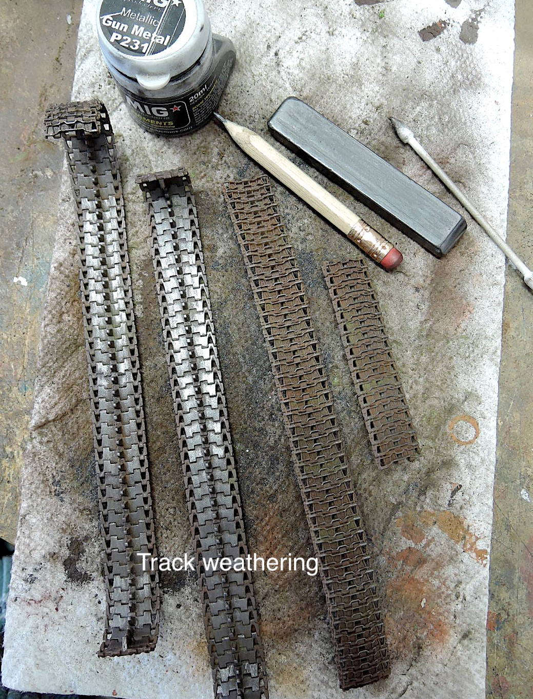
- Tracks - AV Panzer Aces Track Primer, AV Model Air Russian Green, AV Panzer Aces Dark, Light, & Yellowish Rust, MiG Gun Metal Metallic, Allied Green Fading & Dark Mud pigments, graphite wear areas, Mr. Color Silver tread wear surfaces.
- Wheels - AV Panzer Aces Dark & Light Rubber, MiG Russian Earth pigment.
Figures
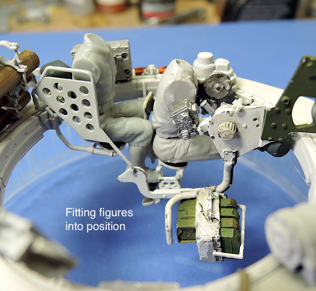
I wanted to install figures in the tank interior to illustrate the crew positions and how cramped the quarters are. The figures are a combination of MiniArt, Dragon, Trumpeter, and Valkyrie Soviet tank crews. Most of the figures measured about 5‘6“ tall, except the MiniArt figures were slightly larger. Even so, it was very difficult to fit the figures into position. The gunner and commander did not sit well in their seats, which may have been too high. The loader particularly needed to be cut down to about 5‘0“ to fit even in a crouched position within the turret. The figures required a lot of cutting and adjusting to fit in reasonable poses. Russian tank crews need to be very small! Hopefully MiniArt will produce Soviet crew figures that will fit inside their nicely detailed interiors.
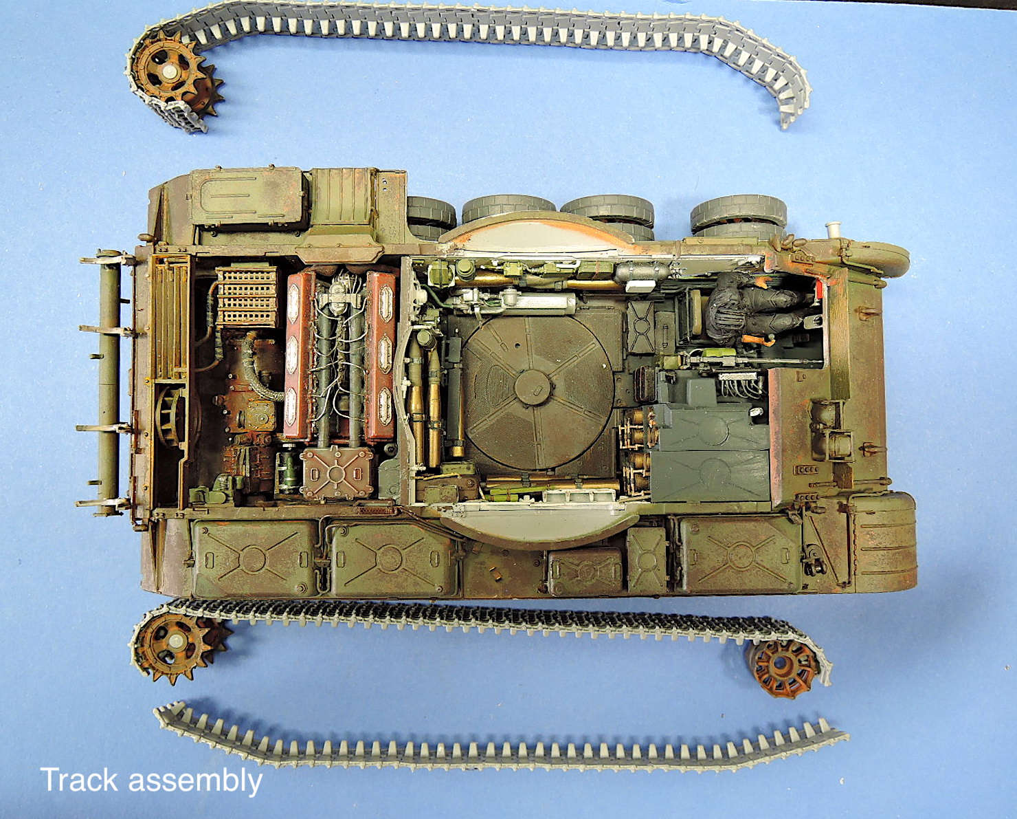
I waited until the end of assembly to install the road wheels and treads. The road wheels and drive sprockets are shown to be attached to the hull in step 43. The pins holding the wheels do not have much of a bite on the suspension arms, so I ended up gluing the wheels to the suspension arms. Individual links for the treads fit just barely tight enough together to shape the treads on the wheels and sprockets for gluing, then allowing removal for painting. The links have 4 sprue connections each, but otherwise don’t require much clean-up. The instructions call out 90 links per side, but I ended up with 89 on the right side.
Summary
This is an excellent, fantastically detailed model kit. MiniArt has produced a kit with the finest detail and best-fitting parts that I’ve experienced! This certainly is a high standard for model kits!
All this detail comes with a price though. Lots of experience working with small (i.e. microscopic) parts, and huge numbers of parts is necessary to complete this model. Patience and lots of time will be necessary to build this kit. I’ve spent more than 250 hours on this build due to the parts & detail added, installing crew figures, making cutouts, and extensive weathering. In spite of the complexities, I’ve enjoyed this build immensely.
Many thanks to MiniArt for producing this fantastic kit and providing the review sample to IPMS! Thanks also to Ben Mirson at MiniArt for helping with my questions.
References
- T-55/T-55A Vols. 1 & 2; Model Detail Photo Monograph No. 9 & No. 12; Pawel Sembrat; Rossagraph.
- Wikipedia


Comments
Add new comment
This site is protected by reCAPTCHA and the Google Privacy Policy and Terms of Service apply.
Similar Reviews