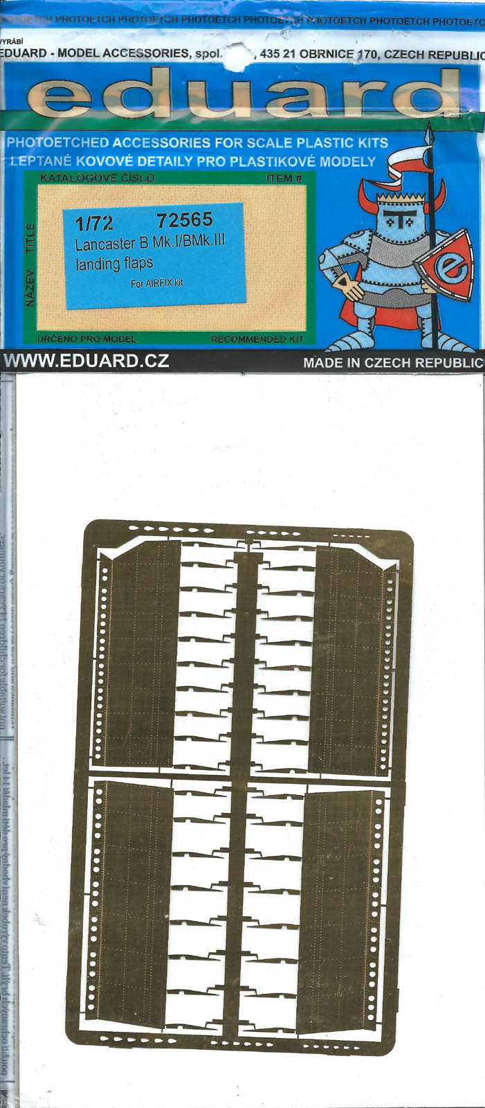
Lancaster B Mk.1/Mk.III Landing Flaps
My thanks to Eduard for furnishing this photo-etch set for review and IPMS for allowing me to do it.
The Avro Lancaster of World War II fame can trace its linage back to the twin-engine Avro Manchester. The Manchester saw a lot of action in the early months of World War II. However, it was underpowered and generally did not meet RAF expectations. Using the Manchester as a starting point the Avro engineers increased the wing span, replaced the two Rolls-Royce X-24 Vultures with four Rolls-Royce V-12 Merlins, lengthened the fuselage and redesigned the tail. The results was a bomber with impressive performance and excellent flying characteristics. Its top speed was 282mph at 63,000 lbs. and its landing speed was 95-100mph using the old split flap design set to full down.
The subject of this review is that old split flap system used on the Lancaster. Eduard has issued a set of brass photo-etched flaps for the 1/72 Airfix Lancaster. These flaps will work with the Airfix Lancaster Mk.I and Mk.III kits.
The flaps come on three brass frets as pictured below. One fret holds the upper wing structure. There are two on each wing – inner and outer. Another fret holds the lower moving slat portion of the wing. Again, there are inner and outer sections. The third fret hold additional structural pieces. The detail on each part is exceedingly fine. The rivet detail on the exterior of the flap is super and the interior comes pre-painted in a nice wood tone. These can be seen in the photos below. Each component is unique to its place on the wing. The components are not interchangeable.
The instructions are on a 5-3/4” X 8-1/4” sheet printed on both side. Page 1 is illustrated below as an example. There is no numerical sequence to the instructions. The modeler will have to be very familiar with the diagrams and parts before proceeding. The upper wing is addressed first. Remove all the ribs molded into the upper wings (A8 and A11) and sand down and putty in the uneven surface to hold the flat photo-etched replacements.
Remove the photo-etched upper wing structure from the fret and carefully bend as instructed. It will certainly help to have a photo-etch bending tool. The photo-etched ribs are delicately rotated into place and set with a little CA glue. An additional structural piece is added to the forward edge of this assembly. The instructions call for placing a 0.8mm rod (not part of the PE set) through the small holes in the ribs the length of the structure. I used stretched sprue for this piece.
I encountered a little difficulty fitting these components into the available space in the upper wing. After a little shimming, filing, and sanding the new wing structures slipped into place. My problems could have been self-inflected through misinterpreting the instructions or my inaccuracy in bending the parts into shape.
The movable portion of the flap design is addressed next. The photo-etched parts are a direct replacement for the kit parts (D11, D12, D19, and D20). First, a ledge molded into the lower wings (B1 and B7) is removed. The photo-etched parts are fabricated in a similar manner as the above wing structure including adding the stretched sprue rod. Once assembled the trick is to set them in place at the proper angle. The instructions indicate using a 0.3mm prop up rod between the top and bottom structures. I used kit part D9, the aft end of the engine nacelle, as my alignment mechanism. Part D9 mounts to the back of the nacelle and the photo-etched piece is laid against it and glued in place.
The end results of this replacement set is very rewarding and will do much to enhance the looks of the Lancaster. While I did have some minor fit issues, it was a pleasure seeing the parts come together. This is an item to be constructed by a modeler with some experience working with photo-etch parts and the proper equipment.
Again, my thanks to Eduard and IPMS USA for allowing me to review this sample.


Comments
Add new comment
This site is protected by reCAPTCHA and the Google Privacy Policy and Terms of Service apply.
Similar Reviews