
KOZAK-2 Ukrainian MRAP-class Armored Vehicle and Combat Vehicles Acrylic Paints Set
Paint Set Number: 3040
Brief History - from Wikipedia
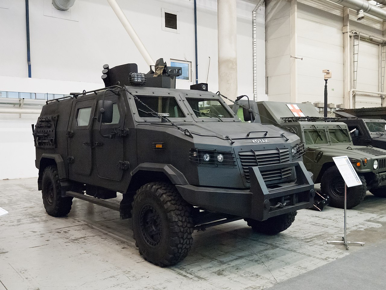
The first Kozak vehicle (also known as Kozak-1) first appeared on August 24, 2009 at the Independence Day of Ukraine military parade in Kyiv. Only two vehicles were manufactured prior to March 2014.
The third vehicle (also known as "Kozak-2014") was built in November 2014 and was intended to be a proof of concept to address a growing requirement for a mobile MRAP. In March 2015 the vehicle was armed with the NSV machine gun.
Another variant, the Kozak-2, was built in 2015 and armed with an anti-tank guided missile system. In May 2015 the vehicle appeared at the 169th Training Centre.
The Ukrainian Defense Ministry conducted comparative tests of 11 armored vehicles from various manufacturers in early 2016, but only three of them, including the Kozak-2, passed the state tests, the Ministry said. The trials of the Kozak-2M1, an improved tactical version of the Kozak-2, continued from October 2018 to July 2019, during which time the vehicle was tested with over 50 techniques and in a simulated combat environment.
The Defense Minister of Ukraine Stepan Poltorak on March 21, 2017 signed a decree officially adopting the "Kozak-2” into service.
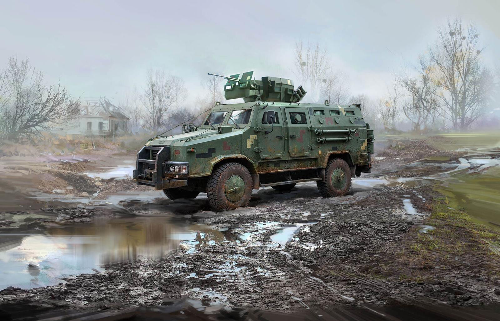
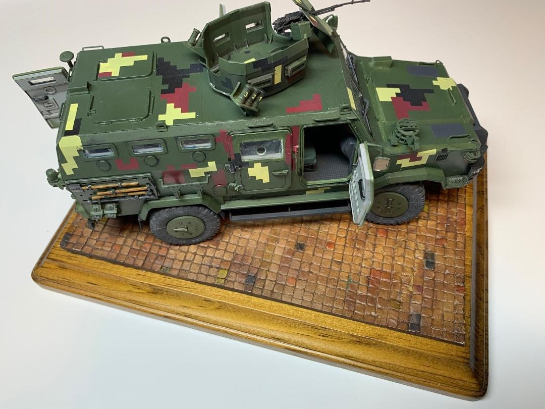
From the kit manufacturer: Kozak-2’ belongs to the MRAP class of combat vehicles – special vehicles designed to protect the crew from mine explosions and ambushes. The tasks that the Kozak-2 can perform include patrolling, escorting vehicles, communications and fire support for personnel in combat. The vehicle was developed by the Ukrainian company PJSC RPA ‘Practika’. The ballistic protection of the armored vehicle is provided by special alloy steel with ultra-high hardness, it also has bulletproof glass. The armor protects the crew from small arms fire of 7.62 mm caliber, ammunition fragments and mines. The crew and troops are equipped with anti-trauma seats with five-point safety belts. The vehicle can be armed with a heavy machine gun or a 7.62 mm machine gun, both of which are mounted in an armored turret with a circular rotation. In the Ukrainian army, the armored vehicle is in service with airborne assault troops, marines and reconnaissance units, and has also been supplied to the National Guard and the State Border Guard Service of Ukraine. Since the beginning of full-scale war, Kozak-2 has been widely used by various units of the Armed Forces of Ukraine.
The Kit
There are seven sprues of light grey plastic parts, two clear sprues, one small photoetch fret, and five rubber tires. Parts are nicely molded with very nice detail. Three decal sheets are included with digital markings for four vehicles. The contents are all packaged in a single clear plastic bag. Two small parts had broken off from the sprues and were loose in the bag in my sample, so it is smart to check the bag before disposing of it.
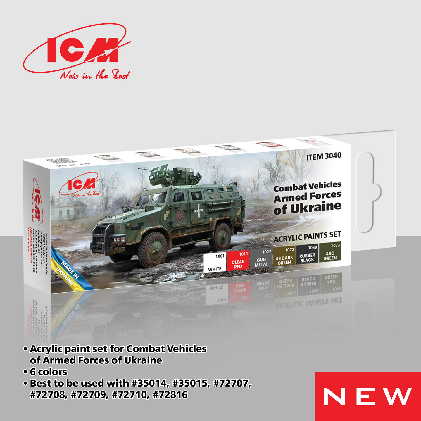
The Paint Set
The paint set included six acrylic paints: white (1001), clear red (1011), gun metal (1027), rubber black (1039) and 4BO green (1073). The paint is prepared for application with a brush from the bottle, for airbrushing requires thinning with water or acrylic thinner 40 - 60%. If using an airbrush a primer is recommended.
Once dry, the colors are permanent and waterproof. They are reported to be resistant to oils, enamels, washes, solvents or any potentially aggressive technique.
These paints will be used in this build and if supplemented by other brands that information will be so noted where applicable.
Instructions
The instructions are provided in a booklet form, with 24 pages. The cover pages included a technical section, vehicle history and a paint color chart based on the ICM acrylic line of paints. Pages 2 through 4 have the sprue layouts shown. Pages 5 through 20 show the 136 (!) construction steps for the build. The last four pages deal with the markings for the four vehicles that can be built.
The construction steps are exploded views with the parts numbered and directional arrows indication how the parts are fit together. Paint colors are called out where applicable.
Confession and Admission of Guilt
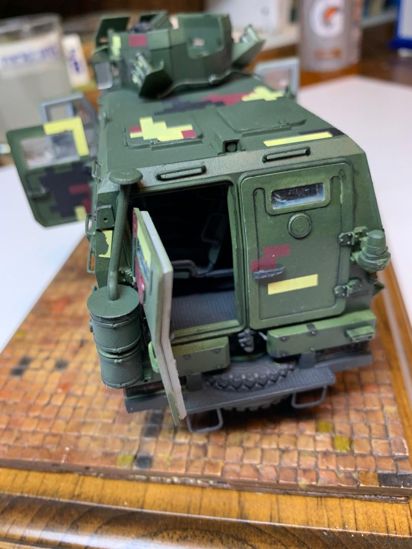
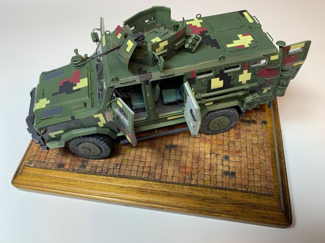
When you look at the images of the completed model you will notice the front, two part windshield appears less than clear. There is a reason for that. Somehow I neglected to mask the clear parts before painting! How I missed that important step after masking all the smaller windows I cannot imagine. The exterior surface had a coat of Tamiya grey primer on it, while the interior surface does not, and I am certain I applied the primer to both sides. How that happened I cannot explain. I was able to remove the primer from the exterior side with a Q-tip dampened with Tamiya lacquer thinner.
An absolutely rookie mistake and I am truly embarassed. This has no bearing on the quality or buildability of the kit. The kit is magnificent. I plan to stand in the corner, facing the wall, until I am ready to face the public.
Construction
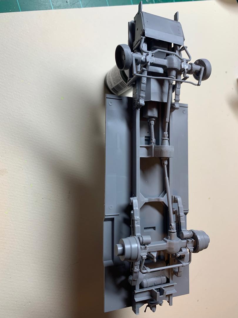
The Chassis Construction
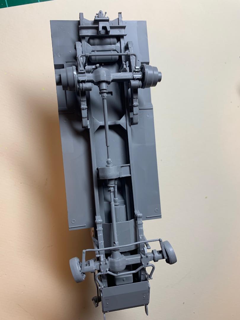
Steps 1 through 26 detail the chassis construction. The first 10 steps deal with the assembly of the frame. There are two long side frame parts fixed together with several cross members. Care is required when fitting all the parts together to make sure the frame is square in both directions before the solvent sets up, however this assembly proved to be reasonably self-aligning. In steps 11 and 12 the engine crankcase is ftted together (three parts) which then fitted to the hull floor. Next, the frame assembly is fitted to the hull floor. The hull floor has four raised tabs that fit into shallow notches in the frame top. Once everything was fitted together I realized the front portion of the frame stood slightly proud of the hull floor. Something was amiss here, but what? I reviewed the on-line assembly video on the ICM website and noted the video showed the front portion of the frame was not tight to the hull. I clamped the frame to the hull bottom and applied the solvent leaving the front gap.
Steps 13 through 17 addresses the assembly of the front drive axel. The front disc brake housings (parts C43 and C44) are included in this sub assembly, and are intended to be installed on the front axel in a straight forward configuration. I decided to fix the brake housings so the front wheels were turned slightly to the right for a more candid appearance. I pulled this off without any difficulty.
The rear axle drive is completed in steps 20 through 26. Everything fit just fine here also and when this major assembly was completed it was set aside over night for the solvent to cure and the joins harden.
Time to paint: I airbrushed flat black primer onto the undersides make sure that I covered all the many nooks and crannies. I also painted the interior floor side of the chassis. Next I tried the ICM Rubber Black 1039. This color was thinned with distilled water at a ratio of 1:1, and airbrushed onto the interior floor. I masked of the floor and airbrushed the console with satin black. It should be noted the console has cup holders molded in place. Cups not included. Looking for 1/48 scale Yeti or two to add to the build.
Wheels and Tires
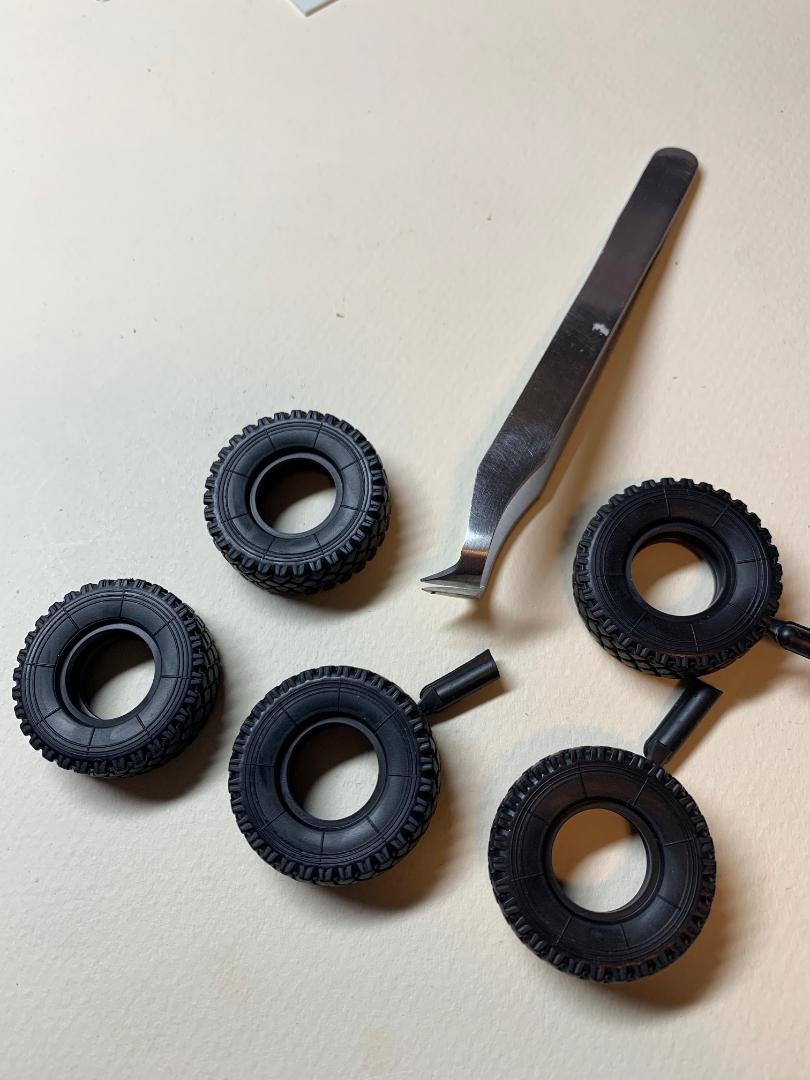
The assembly on the five wheels and tires is shown on pages 14 and 15. The assembly of the spare, the two front wheels and the two rear wheels are detailed in five steps, with the placement shown in step 98 Each of the wheels are made from four plastic parts plus the rubber tire, while the underside stored spare has one less plastic part.
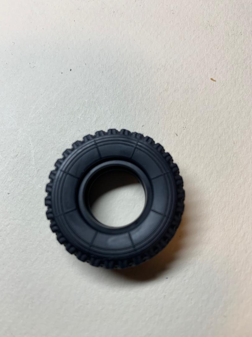
First thing I washed the five rubber tires with Dawn detergent and warm water, scrubbing the surfaces and tread with and old tooth brush. The tires were rinsed in warm water and set aside to dry overnight. Once dry, and as a further precaution I swabbed the tires with isopropyl alcohol.
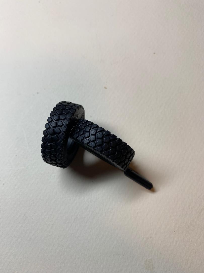
I inserted a common pin into the tread side of each tire to facilitate holding the parts during painting. I feel the natural rubber tires provided in AFV kits do not look realistic (too glossy) if left unpainted. I first primed the tires with a Tamiya fine grey primer and allowed that to cure for 48 hours. I airbrushed the tires with the ICM rubber black and then I airbrushed Panzer Aces dark rubber (a very thin mix) over the tires. Now it looked like rubber in 1/35th scale to me.
The plastic wheel parts were first primed with Tamiya fine grey primer and allowed to cure for a day. The inside rims were painted ICM Rubber Black while the exterior hubs were painted with ICM 4BO Green. Both paints applied with and airbrush. Later the exterior hubs were slightly weathered and sealed with clear flat.
I found that the exterior hubs did not seat fully when inserted into the rubber tire. I tried pulling the rubber with my fingers in opposite directions while forcing the hub in place with my thumbs. The hub did not seat in the tire as well as I would have liked.
Interior
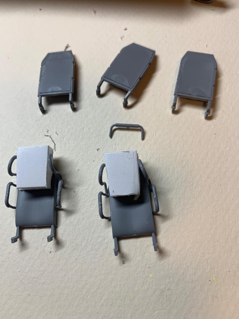
Steps 27 through 49 detail the interior assembly. The seats are comprised of several parts for each, are are nicely detailed. The side rails for the two front seats will set the back rest angel. The dash board and steering column do include a few very small parts that will require care when removing from the sprue and more care when fixing in place. The gear shift and four-wheel driver selector are prime examples of micro parts. Separate accelerator, brake and clutch pedels are included. The steering column is also fitted with two tiny levers (turn signal and windshield washer?). Each fit into shallow depressions opposite each other on the column. I drilled out the depressions for a better fit of the two levers. This sub-assembly was painted satin black.
There is seating for ten crew members. Six seats are set back-to-back in two rows of three in the rear compartment. Parts D49, D50 and D-51 form the hand grips and roof cage for the infantry. The seat restraints with mine protection require some care to fix in place and required a small piece of foam board used as a spreader to achieve the correct space before the top bar is glued in place. It was quite amazing the amount of detail and the number of parts that went into each seat. This was the most time-consuming part of the build at this point. Each seat was painted before fixing in place on the cabin floor. Seat belts were not included.
The installation of the seat restraints are the most tricky part of the assembly. The parts are rather dainty and the attachment points are quite minimal. Go slow and have patience with this assembly.
Note: if I could do this part over I would assemble the six crew seats on the mounting frame and add the individual seat restraints after painting. Handling the seats with the restraints in place resulted in a few that broke off.
Exterior
Steps 50 through 120 detail the exterior assembly.
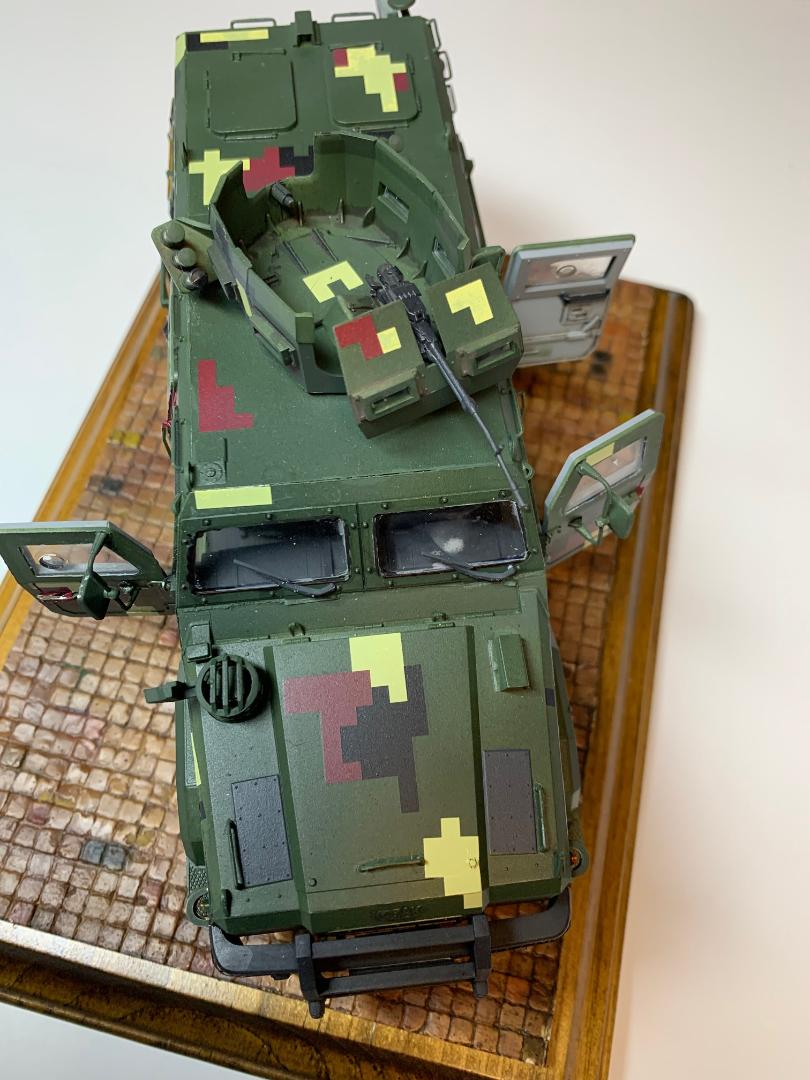
The cabin side and rear walls and the separate doors are all sandwich panels, which is really slick as the ejector pin marks are all concealed between the panels. The three, high wall windows in the side wall of the cabin must be fixed in place before the interior panels are glued to the exterior panels. The clear parts will require masking on both sides.
There are six crew access doors, two on each side and two on the rear. Each door is a sandwich design with the window trapped between the interior and exterior panels. The clear parts fit into recesses in the exterior door panels, with a very precise fit. I used ZAP Formula 560 canopy glue applied with a toothpick to hold the clear parts in place. I also clamped the interior and exterior panels together to assure a tight fit before applying the solvent to the seam. The interior and exterior handles are separate parts, plus a separate grab bar (part D5) mounted vertically on the door. Part D5 is quite delicate and was difficult to clean up the attachment spure, and therefore I replaced these parts with fine copper wire bent to shape and fixed in place with super glue. Each door appears to be designed to be posed closed or open. I test-fitted one of the rear doors in a closed position and the fit was precise. No concerns about gaps here.
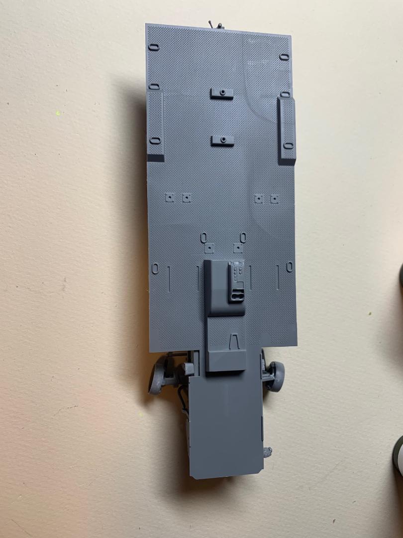
With step 54 the right side of the crew compartment is fitted to the chassis/floor assembly. The floor fits into a horizontal linear slot along the bottom of the right side panel. Tamiya solvent is applied to the slot and allowed to flow along the join. This was allowed to cure slightly before the left side panel is installed. In step 57 the left side is fixed in place and held in place with clamps front and rear. The parts were set aside to cure for several hours before moving on.
Step 57 details the assembly of the left side of the crew compartment and the fitting to the chassis, just like the right side.Steps 58 and 59 show the assembly of the windshield and hood.The angle of the windshield looked to be self-aligning with the front angle of the two sides, but it is not. I recommend fitting the windshield to the hood by aligning with the two sides of the crew compartment. I followed steps 58/59 and ended up with a slightly wrong angle on the windshield. I applied solvent to the inside of the join between the hood and windshield and when the join had softened sufficiently I fitted the parts in place and allowed the join to harden in the correct angle. After that I glued the assembly in place. Now it fit.
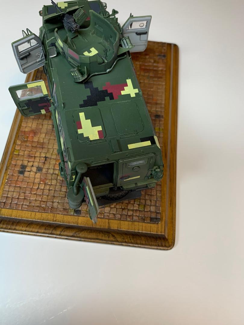
Roof Gunner Position
Steps 121 through136 detail the assembly and placement of the various parts. The kit's clear parts were installed after the turret was painted and decaled.
Painting
This is the first time for me to use the ICM acrylic paints, and therefore a bit of testing and experimenting was required. I planned to use an airbrush for the majority of the painting, and the manufacturer's recommendation was a 40-60% thinning. I decided to use distilled water for the airbrushed colors with a 1:1 ratio of paint-to-thinner. When I brush painted surfaces I would thin the paint with distilled water, just a drop to start.
First, I masked the clear parts (except for the windshield!!) with masking tape and masking fluid. I painted the interior of the hull components with a light grey and sealed that with Future. The exterior surfaces were air brushed with the ICM 4BO Green. It required three light applications to achieve the results I was after. The parts were set aside to cure for 24 hours.
Weathering
I planned minimal weathering for this build. I used a number 2 graphite pencil to high-light the various edges on the vehicle's undersides, and for scuffs and I used a silver prismatic pencil for scratches to the crew compartment floor.
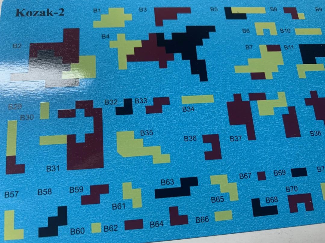
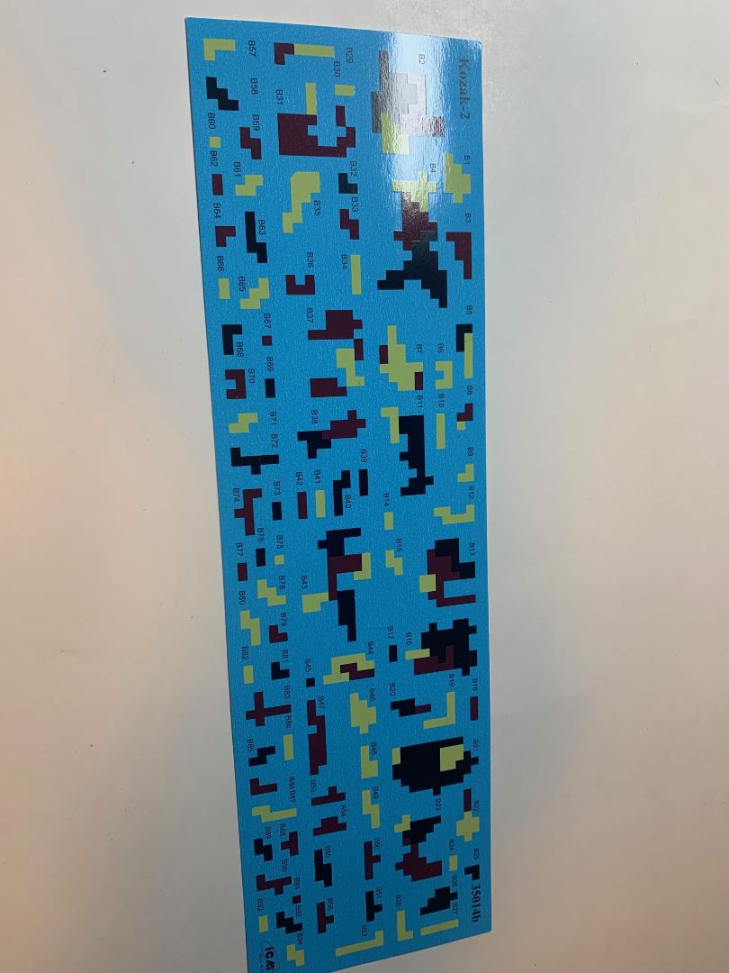
Decals
First, I applied a clear gloss coat over the model and allowed that to cure for 48 hours.
There are four marking options for the model. I chose the markings for the 35th Separate Marine Brigade of Ukraine, January 2021. Page 21 of the instructions show a five view layout for the decal placement. Each decal is numbered, with the locations noted in the various views. The decals sheet I used is a long, rectangle and the numbers are sequential which made it easy to cut out the individual markings without having to search the sheet and find one located in the center. There is ample room around each decal to facilitate cutting the decal out.
After a quick dip in water I placed the decals on a damp sponge, decal face up, to allow the markings to loosen, which generally took about a minute. I used MicroSet to place each decal, then lightly blotted it with a folded paper towel. The I applied MicroSol. The decals are thin and settled down quite nicely on the flat surface that had some subtle raised detail. Over the door hinges and door fames, where the detail was a bit more raised there was some bridging, but once again the solvent helped the decals settle in place. A few needed to be cut to help with the fit.
Once the decals were placed and allowed to dry a clear, flat finish was applied to the model.
Conclusion
The Kit
This is a complicated kit with many parts, especially small ones. It seemed at times that ICM went out of the way to include several small parts into the build, but with care and planning all went well. The engineering and fit is top notch, and in my opinion well thought out. This is certainly not a kit for the beginner, but others will enjoy the effort required for the assembly as well as the end results. I certainly enjoyed the build. Some may complain about the part count and the number of very small parts involved. However if you want the high level of detail in your kits lots of parts and small ones may be necessary.
The ICM web site offers some useful tools to facitate the assembly of this kit. This particular kit is shown with several CAD views from various angles showing the detail included in the kit. A video instruction feature is also included. This offers potential buyers the opportunity to see what is included before making the purchase. I was very impressed by the content in the images and that was a deciding factor in my volunteering to build and review this kit.
The 8 minute video compliments the instructions and will be a big help in the assembly. Sometimes the placement and orientation of certain kits parts may not be exactly clear in the two-dimensional instructions as usually found in most kits. The video will certain alleviate some of those concerns and will help clarify placement of the parts. Parts count is shown as over 400 parts. Many are small and the video helps with the placement. I watched the video several times during the course of the build to help in the basic assembly as well as the planning of the painting. The music in the video isn't bad either.
The Paints
The paints are rather thick and I used a small craft stick to transer the paint to a small jar where it was mixed with distilled water. ICM recommends a 40-60% thinner ratio to the paint. I am certain that I exceeded that ratio, however the paint hand-brushed and airbrushed beautifully. I certainly recommend this paint for anyone who is a fan of acrylic paint. The plastic must be primed before the paint is applied.
What would I do differently if I were to build this model again? The doors are sandwich panels, trapping the clear part between the two sides. A small recessed is created on each side of the clear parts. Next time i would paint and finish the interior and exterior sides before gluing them together, trapping the clear part between the two finishedsides. This would eliminate the need to mask the clear parts. Masking was difficult and paint did creep onto the clear parts near the exterior and interior panels.
I wish to thank ICM and IPMS USA for the opportunity to build and review this kit. Very highly recommended for the experienced builder (plan to dedicate a good deal of time for the assembly and painting). This will make for a nice modern military vehicle for adding to one"s collection.
Comments
Add new comment
This site is protected by reCAPTCHA and the Google Privacy Policy and Terms of Service apply.
Similar Reviews