
WWII RAF Airfield
Summary
This can be considered a “diorama-in-a-box” in that it contains everything one would need to create a nice airfield diorama. There are some frustrating fit issues, so I would recommend this kit to any modeler with a good dose of patience.
Background
The Spitfire MkVII airframe was based off of the MkV. It incorporated the improved Merlin 61 series engine. It was designed as a high-altitude interceptor and thus had a pressurized cockpit. It also had extended wing tips and the later large (pointed) rudder.
The MkIX was a later variant incorporating the Merlin 66 and later engines. Armament consisted of two 20mm Hispano cannon in the inboard position and four .303 browning machine guns in the outer positions. While most had the standard round wing tip they could be fitted with the clipped wing tip for low level operations. This variant could also carry a 90-Imperial gallon slipper tank as well as bombs and rockets.
This kit depicts the 4x2 mobile command post with radio communications for battlefield management of ground troops.
The Kit
When I received this kit for review, I was expecting a box of figures and airfield accessories (RAF Photo 1). So one can imagine my surprise when I opened the box and was greeted by three bags of sprues, one with the aforementioned figures and accessories, the other two with complete Spitfire kits. All are modeled in a medium grey color. The bag of figures and accessories come on a single sprue with a one-page instruction sheet. The Spitfire bags each contain five sprues each with a four-page instruction book and a single sheet with painting diagrams and decal placement. There are three identical sprues in each kit (C, D, and E) with parts for a variety of Spitfire variants including; early and late tail planes (single versus double elevator kinks); rounded and pointed rudder; standard (rounded), pointed and clipped wing tips; cannon bay covers with narrow with the blister to the front of the panel, narrow with the blister to the rear of the panel, and wide long blisters; short and long cannon barrels; two types of chin (smooth, for use with the short air intake trunk and with the extended air intake trunk); rectangular and circular rearview mirrors; and bomb and rocket armament. I’m guessing that only the A and B sprues that hold the fuselage halves are different between the kits, but more on that later.
All three bags had part labels on them. I noticed that the two Spitfire kits had identical numbers, but wasn’t sure if that was a problem. More on that later.
The Instructions
The instructions are a single 8½ x 11-in sheet in landscape orientation and folded in half.
The front of the instruction sheet for figures and accessories has the part number, The kit number in parenthesis, a description in in Cyrillic and English. Below this header, the upper portion is a parts map of the sprue, while the lower portion are exploded view drawings for the accessories. There are five accessories are a gas cylinder cart, A work bench with a “vice” for loading bullets into a belt, an A-frame lift, a wooden ladder, and two jerry cans. The upper two-thirds of the back of the sheet shows the instruction and painting call-outs for the figures. The lower third is the color call-outs. Colors are given by, the now discontinued, Model Masters enamel number and color. The color, like the header, is given in both Cyrillic and English. The bottom portion includes Cyrillic and English cautions and ICM address.
There are two different Spitfire kits, one for a MkVII and one for a MkIX. Like the figure instruction sheet both of these have a header with the part number, parenthetical kit number, and description (in both Cyrillic and English). Below the header is a sprue parts map followed by 13 build steps for the MkVII and 16 steps for the MkIX. The rear page has the paint color call-outs, cautions, decal application method, and ICM address.
The second Spitfire sheet differs between the two kits. The front of the MkVII sheet has the header, a left-side view of decal option 1, a right-side view of decal option 2, a color call-out table, cautions, decal method, and ICM address. The MkIX front has just the header and a four view (left, right, top and bottom) drawing of decal option 1. The back of the MkVII sheet has split top and bottom views for the two decal options. The back of the MkIX sheet has a three-view drawing (left-side, top and bottom) of decal option 2 and the ICM address.
Construction
Construction of the figures and accessories is simple and straight-forward. The figures are well molded with crisp detail and easy to clean mold seams. I suggest painting the non-molded-on figure accessories separately for ease of painting. Pay attention to the position of the hands on the pilot figure wearing the May-West to make sure they impart the correct angles. For the outfitted pilot and assistant use one of the aircraft models to help get the hand placements correct. The only issue I had was with the pilot holding his jacket over his shoulder. There is only minimal contact between the jacket and the figure, so it took a couple of efforts to finally get them cemented together. Lettered paint call-outs are included in the drawing for each figure/accessory.
Building the accessories is likewise straight-forward. Here the biggest issue with the scale thin pieces. I broke a couple of the parts for the cylinder cart and A-frame lift just removing them from the sprue. Then also broke most of them again in putting them together. Although it is not clear in the drawings, I placed the angle braces for the work bench flush to the outside with the inset facing in. Also not clear is that the “rings” of the two gas cylinders should line up with the brackets on the cart.
The Spitfire builds are identical through Step 9. Again, lettered paint call-outs are made throughout the build instructions. Steps 1 is the construction of the engine. These are beautiful little kits in their own right with a fair amount of detail either molded on or glued on. There is one “Fatal Flaw” with these that I will address later. Step 2 attaches the engine to the engine mounts and firewall along with the oil tank. Step 3 show the option of removing the pilot’s door to pose it open. Steps 4 and 5 are the installation of interior detail. Step 6 joins the fuselage halves capturing the engine “egg” between them. There is also an option here to replace the engine cowls for different variants. For variety I used the optional side cowlings for the MkIX model. Removal of the molded cowlings is easy as there is an engraved line on the interior as a guide. However, use care and cut along the edge closest to the front of the aircraft. I did this and still had a gap that needed filling. Step 7 builds the basic cockpit, while Step 8 completes the cockpit “tub”. Step 9 installs the cockpit tub into the fuselage and adds the tail wheel. This is where I noticed that, in fact, the kits were identical. The only external difference, other than some engraved panels, is that the MkVII has a retractable tail wheel, while the MkIX is fixed.
Step 10 is where the builds “diverge”. I will continue the build description with the shorter of the two, the MkVII. Step 10 is installation of the rudder, formation light, antennae, canopy, rearview mirror, and top cowling. There is an option to show the canopy open or closed. Both versions share the front windscreen. The closed version is a single piece, while the open has the sliding portion and rear portion as separate pieces. The canopy parts are extremely clear and thin.
Step 11 is construction of the landing gear. Step 12 is construction of the wings. Here the option for the wing tip, open or closed gun bays, gun bay blister shape, and long or short cannon barrels. Machine guns and 20mm cannon are included for placement in the gun bay. However, note that if the 20mm cannon is used there is no machine gun adjacent to it. There is also an option for a drum feed or belt feed for the 20mm cannon. References here critical to ensure the correct options are combined for the variant being modeled. Following the instructions and my references I installed the tall pointed rudder, long pointed wing tips, and the narrow forward cannon faring to create a high-altitude interceptor.
Step 13 is the completion of the model with installation of the landing gear and other under-wing components. There is an optional slipper tank that can be added. An important note in this step is the need to shorten the outer alerion (Parts C4 and C5).
Because of the option for underwing stores the MkIX instructions combine attachment of the wing and upper fuselage parts into one step (Step 10). There are multiple options to consider in this step so again good references are essential. I used rounded rudder and wing tips, and belt feed for the 20mm cannon.
Steps 11 through 13 are the underwing stores of rockets, 500-lb bomb, and 250-lb bombs, respectively. Not sure why but for this version the construction of the propeller is a separate step (Step 14) instead of an insert like MkVII. Step 15 is construction of the landing gear.
Final assembly (Step 16) is the same as for the MkVII model, with attachment of the landing gear, underwing intakes, and underwing stores. I did not use any of the underwing stores on my model, but did use the two-piece lower cowl with the extend air intake trunk. The pieces fit well and required only minor filling and sanding to eliminate the seam.
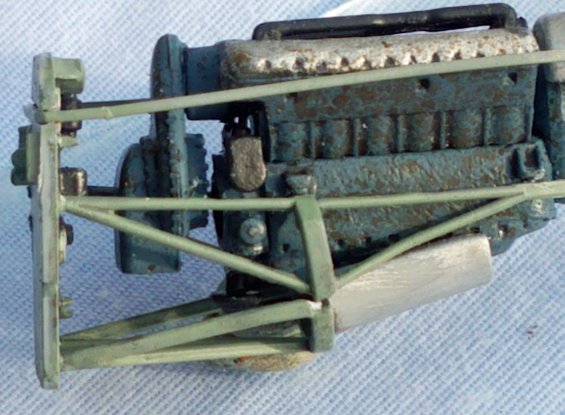
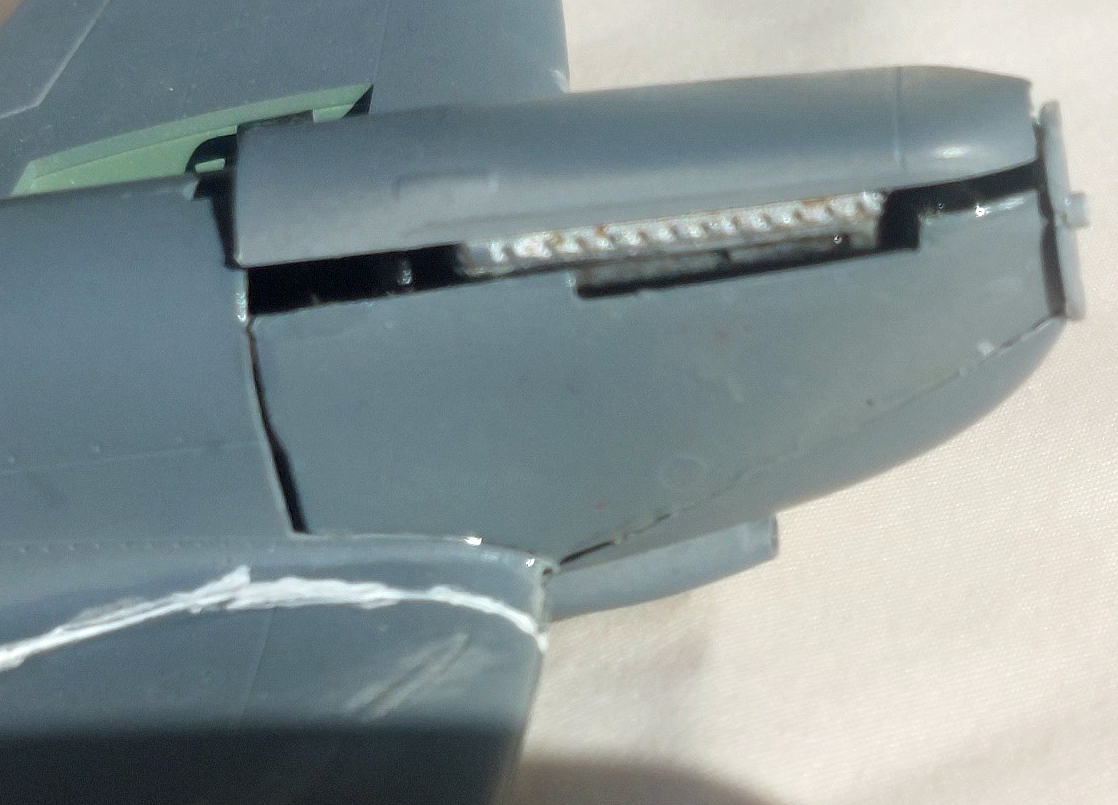
Now a discussion of the engines “Fatal Flaw” mentioned earlier. With the first model I followed the instructions as shown. However, when I went to attach the upper cowling in Step 10, it was not even close to fitting (RAF Photo 6). So, for this MkVII model I decided to show off the engine and left the cowling cover off. Thus forewarned, when it came time to build the MkIX, I was careful to place the engine cylinders and covers at a flatter angle on the engine block. This still didn’t solve the problem. Because the propeller attaches to a shaft that is part of the engine and the exhaust attach to the engine block, leaving the engine completely out is not an option. So, in the end I left the valve cover (Part A23) off completely. I also left out the lower oil pan to get a better fit of the lower chin.
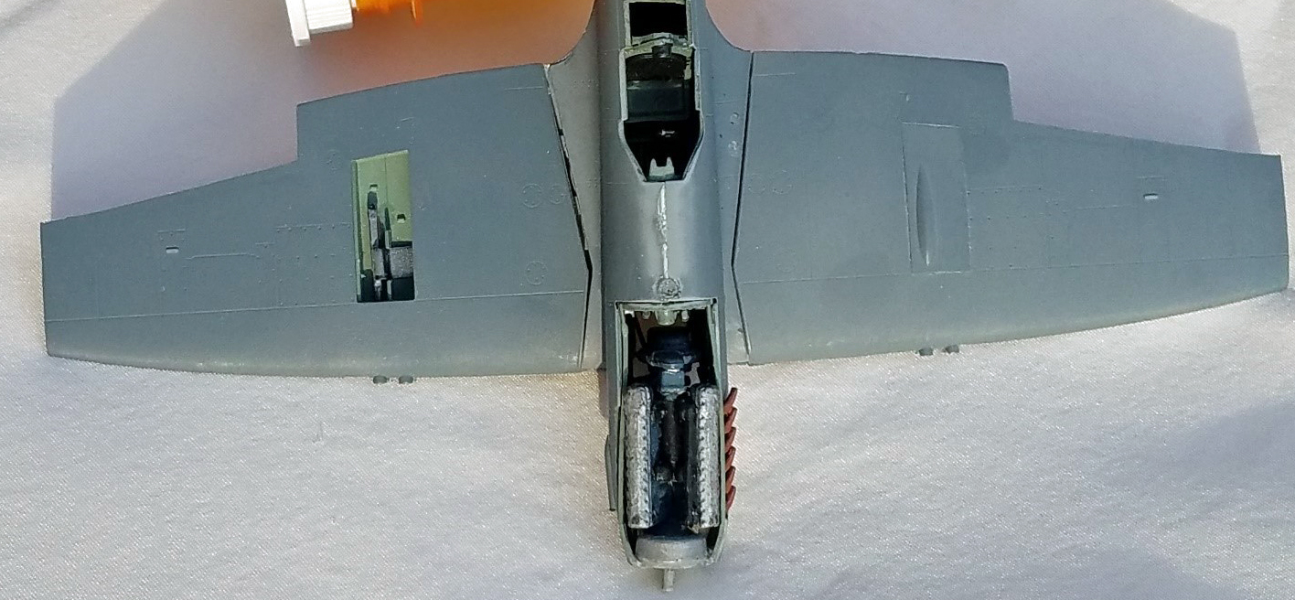
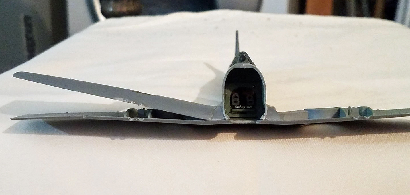
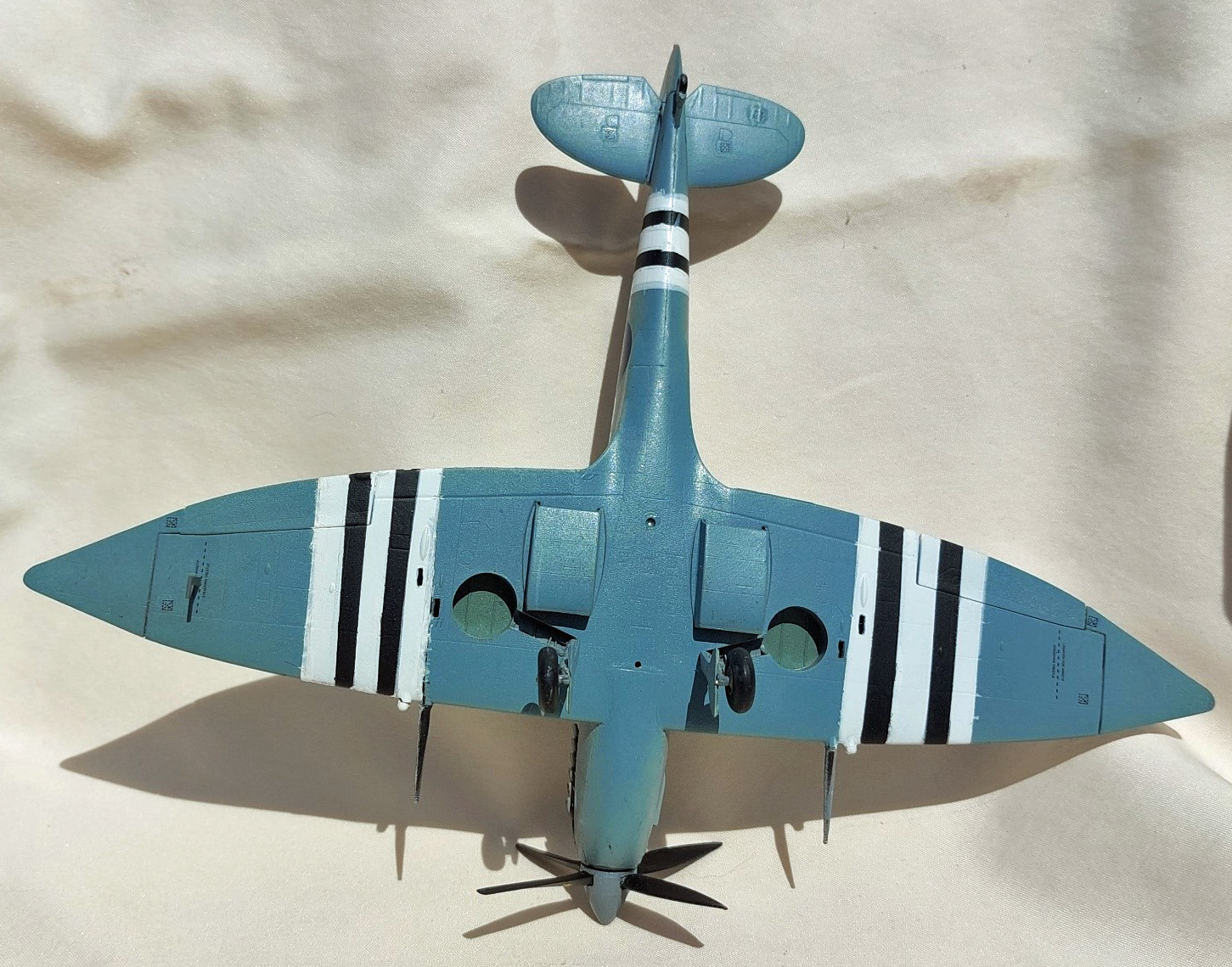
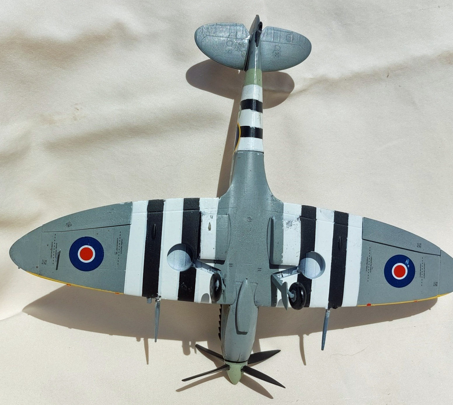
The other big issue is with the wing. Like many aircraft models it is molded as a single lower piece with two upper wing pieces. As most are aware the Spitfire wings have a noticeable dihedral to them. However, the lower wing part is molded flat (RAF Photos 7 and 8). The lack of dihedral becomes more apparent after attaching the upper wing pieces as there is a large gap at the wing root. If one bends the wings up to close the gap the correct dihedral is obtained. I tried lifting the wing tips by attaching tape to both across the model and applying standard model glue. But this didn’t hold once the tape was removed. In the end I used super glue at the wing root while tape held the wings up. As an aside, on the second model (the MkIX) I made an effort to soften the plastic and “warp” the wings before attaching them. This didn’t completely solve the problem, but did make the use standard model glue practical.
Painting and Finishing
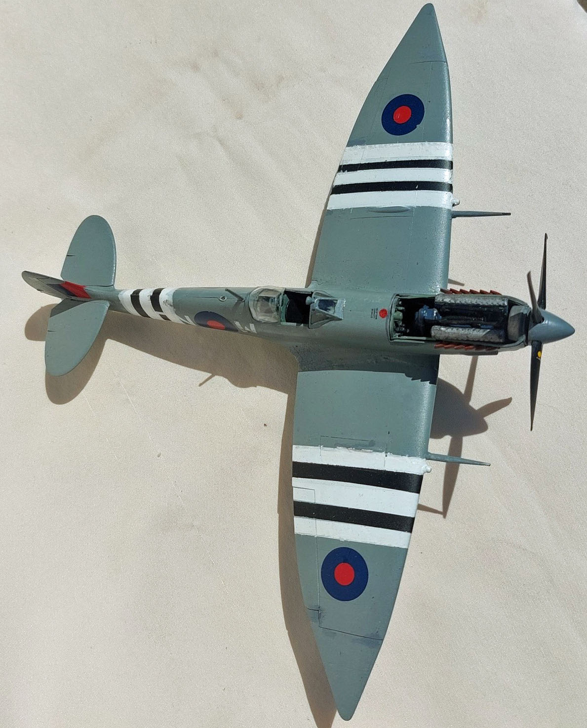
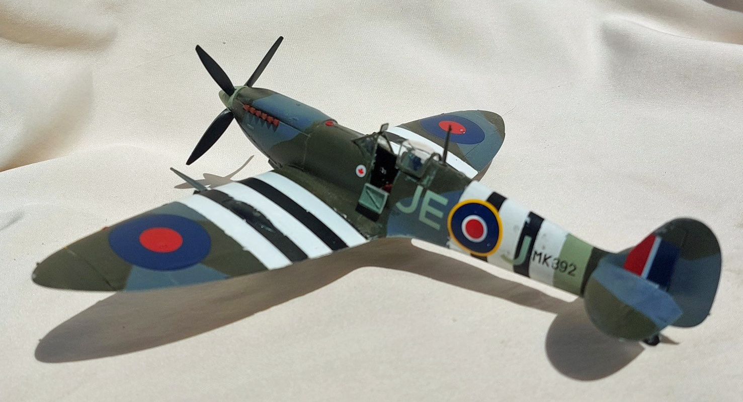
There are two decal options for each model, with one of each having full invasion stripes. The MkVII has an option for an aircraft from 131 Squadron in March 1944 and one for 124 Squadron in June 1944. The MkIX has options for an aircraft from 611 Squadron in 1942 and one from 144 Wing in June 1944. Since I wanted to pose the aircraft together, I used the two 1944 invasion stripe options.
I started this kit as I do all my builds. Washing the sprues in warm water with dish detergent and scrubbing the parts with an old toothbrush. I then primed the parts while still on the sprues with Krylon ColorMaxx Gray Primer and Paint. I used a mix of Model Master (MM), Tamiya, and AK Interactive paints for painting the models and figures.
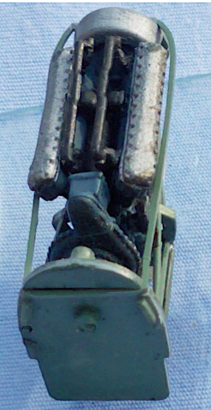
Interior and engines: The engine components for the MkVII are called out as intermediate blue for the engine block and cylinders and medium gray for the super-charger, drive, and coolant pipes (RAF Photos 2 through 5). Try as I might I was unable to find any references that showed a medium blue Rolls Royce engine, so I used gloss black instead of intermediate blue (photo xx). For the MkIX model the call-outs are RAF medium sea gray for the intermediate blue parts and RAF ocean gray for the medium gray parts, respectively. In this instance I was able to find images of gray engines so I used the instruction call-outs.
The fire wall, engine braces, cockpit interior components, gun bay interiors, and wheel wells are called out as MM 1764, European Green. Again, I was unable to find any images of Spitfire interiors in this color green. So I used MM 4850 RAF interior green. Based on my references I painted the wheel wells green on the MkVII only. My references showed later Spitfires with wheel wells the same as the underwing color. Other cockpit details were painted as call-out in the instructions.
The 20mm cannon and feeds were painted gun metal as called out in the instructions. The landing gear were also painted as in the instructions, with the exception of substituting medium sea gray for the called out European green on the MkIX.
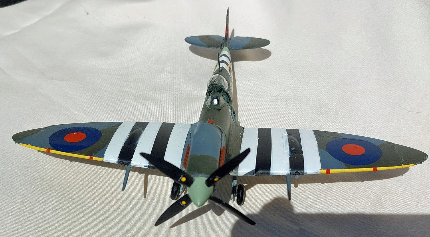
Camouflage Coat: The single-color exterior for the MkVII was easy. I used AK RC237 medium grey for the upper and Tamiya XF‑23 light blue for the underside (RAF Photos 9 thru 12). The MkIX wears the late war ocean gray/dark green over medium gray with a sky spinner and fuselage band. I used mostly Tamiya paints for these, XF-62 Ocean Gray 2 (RAF), XF-61 Dark Green 2 (RAF), XF‑63 Medium Sea Gray 2 (RAF), and MM 4840 RAF Sky Type “S”. I used the Type A camouflage scheme (RAF Photos 13 thru 16).
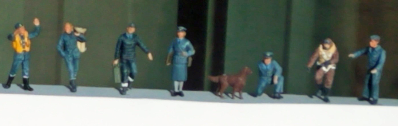
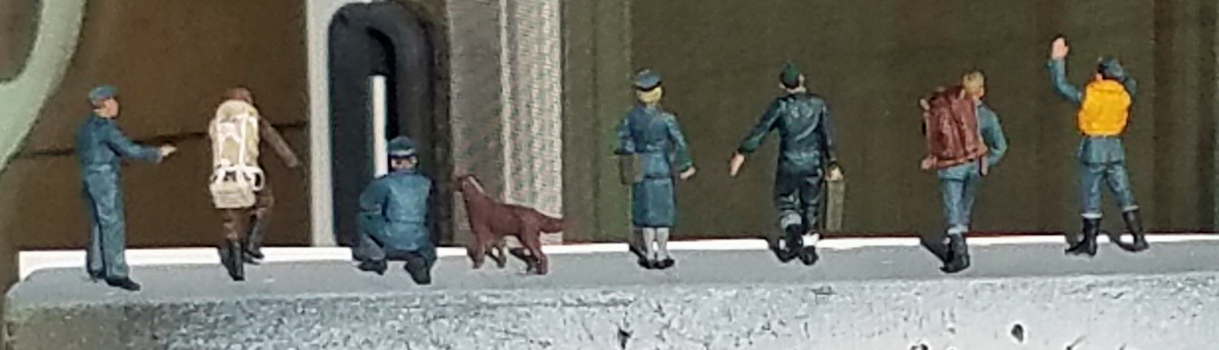
Figures and accessories: The figures and accessories were painted as per the instructions using mainly Tamiya paints (RAF Photos 17 and 18). I used XF-18 Medium Blue for the intermediate blue call-out. This is the overwhelming color for the figure uniforms. For flat sea blue I used XF-17 Sea Blue. The only real variation I made was to paint one cylinder green and one red, and just the bases flat black.
Decals: Decals were applied over a Humbrol Enamel Gloss Varnish (35). I used the Red and Blue MicroSol/MicroSet products to apply the decals. For the most part the decals went on without incident. Make sure the area where the decal is to be applied is puddled with water and float the decal off the backing paper onto the model. Then use a toothpick (or other fine object) to hold the decal in place and wick away most of the excess water. I had trouble with a couple decals where there was insufficient liquid on the model and the decals adhered immediately to where they were slide off the backing paper. Once dry, I gave the entire vehicle a coat of Humbrol Semi-gloss Varnish to seal the decals and prepare the surfaces for future weathering.
Conclusion
Overall, this kit supplies everything one needs to create a very nice RAF airfield diorama (RAF Photos 19 thru 21). The shortcomings with the fit of the engine cowling around the engine, while frustrating, is easily overcome by leaving off certain engine parts. Or, alternately, leaving to top cowling off to show of the nicely done engine. The scale thin parts for the cylinder cart and A-frame lift require extreme care when being removed from the sprue and during construction. The figures are all nicely molded with excellent detail. They do appear a bit smaller when compared to other 1/48 scale figures.
I would like to thank ICM for providing this kit for review, and to IPMS USA for giving me the opportunity to build it for review.


Comments
Add new comment
This site is protected by reCAPTCHA and the Google Privacy Policy and Terms of Service apply.
Similar Reviews