
Westland Whirlwind FB Mk.1
The Westland Whirlwind was a twin-engine fighter/bomber built for the Royal Air Force. It was conceived shortly before WW2 broke out and went into service almost immediately. It was an aircraft not readily mentioned that fought gallantly through the Battle of Britain and the other campaigns in Europe. The aircraft suffered from what many consider an underrated Rolls Royce engine. Although I have also read the propellors were to blame for poor upper altitude performance. Nevertheless, the Whirlwind could out turn the BF-109 and was formidable with its four Hispano 20 mm cannons in the nose. It was also a marvel of engineering in its construction and innovative designs. Unfortunately, all but one airframe was removed from service in 1943 and scrapped.
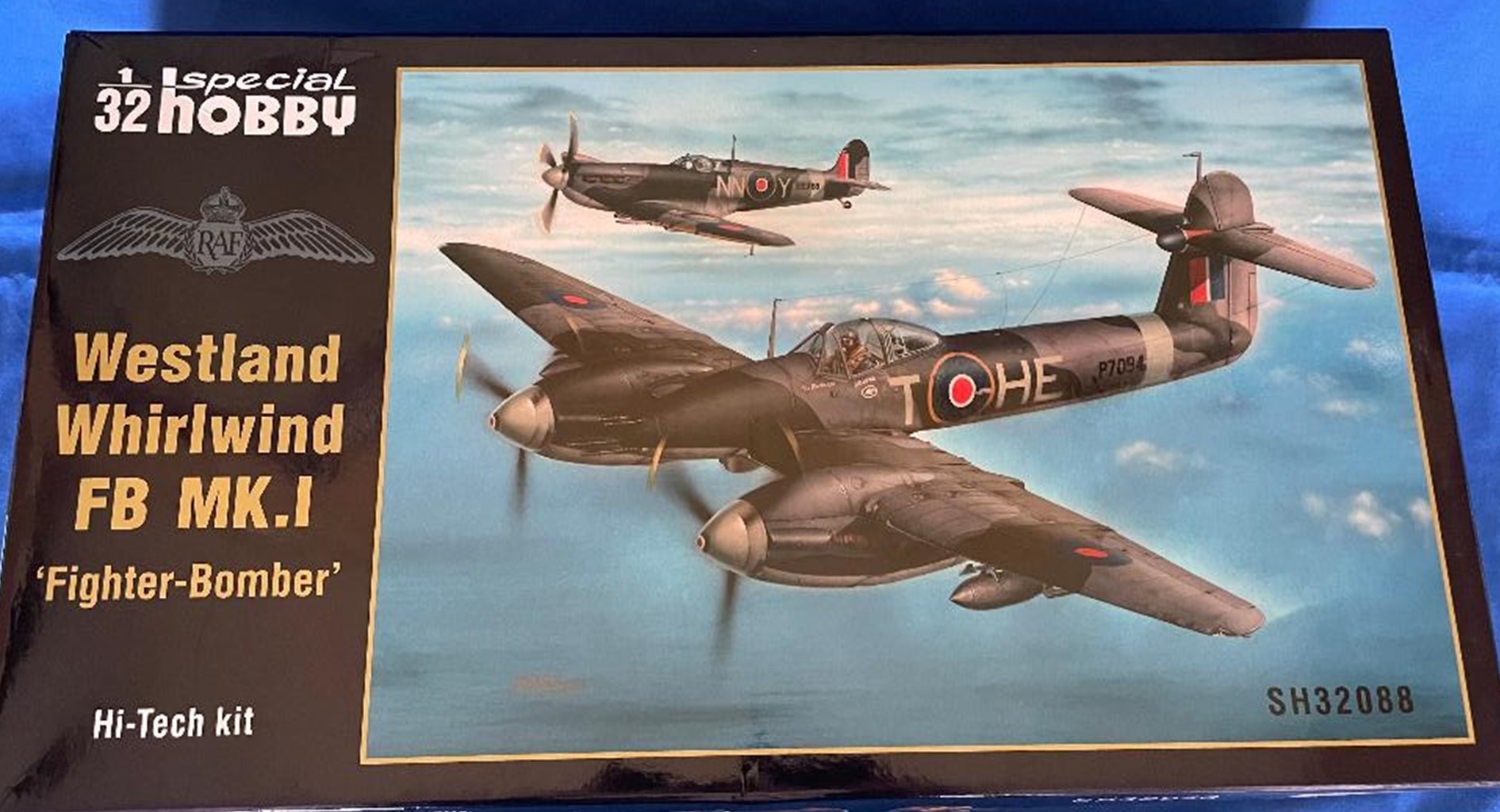
This model kit was the second release of the already, very nice Special Hobby’s 1/32 scale Westland Whirlwind Mk. 1 and represented the “Hi-Tech Kit”, Whirlwind FB Mk.1 Fighter/Bomber, or as it was affectionately called the “Whirlybomber”.
The box top showed a great rendition of Whirlwind P7094 being escorted by a Spitfire on their way to the target.
The standard, strong Special Hobby box was full to the brim with all the grey plastic parts that came in the first boxing: SH32047 protected in two clear plastic bags, an instruction manual, clear parts and two decal sheets.
The “Hi-Tech” part of this kits included a large yellow box from CMK full of beautiful resin and 3-D printed parts to build a complete replica of the four Hispano cannons and mounting assembly within the exposed nose section of the aircraft, as well as a two-piece resin nose cone, replacement parts for the cockpit and weighted wheels.
Eduard provided two photo etch sheets. One containing color, photo etched seat belts and the other for the cannon bay and other areas of the aircraft. Special Hobby included their “Special Masks” set for masking both inside and outside of the canopy and windscreen, landing lights and wheels. I had not built a “Hi-Tech” Special Hobby kit before, but I was very impressed with what was included and the quality of the parts from these Czech Republic model companies. Eduard, CMK and Special Hobby have always been synonymous for producing exceptional quality products in my opinion!
Building this kit, the builder should keep in mind that it is reminiscent of a short run kit. The kit parts did show some beautiful, restrained panel lines and rivet detail. However, it also exhibited some large mold seam lines, a few spots of rough edges with some flash plus a few inconsistent, shallow panel line/rivet detail. Other parts, especially smaller items, were beautifully molded with crisp detail. None of this is intended to be a negative against the kit or Special Hobby, but a little work will be needed to do this model the justice it deserves.
Before commencing construction, I determined that it was necessary to remove all the 3-D printed parts contained within two 3-D printed “boxes” and cleaning up the tiny attachment points. I also separated each resin part from its pour blocks. All of these parts were then attached to toothpicks preparing them for painting. Each resin and 3-D part were clearly shown and numbered in the instruction manual. The two spaces in the forward, nose bulkhead required opening and sanding.
All the 3-D parts were printed in orange, but Mr. Hobby Color paint covered it very well. Al the resin parts were grey.
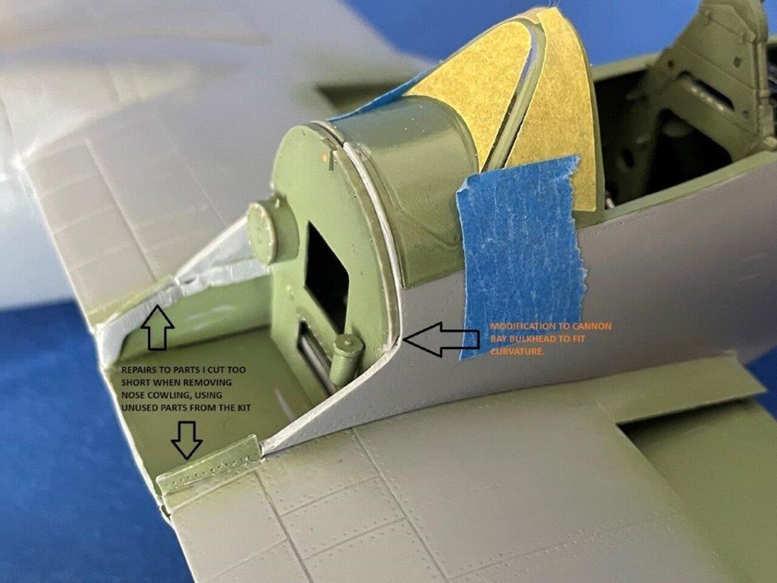
Step one in the instruction manual, construction started with removing the nose cowling from each fuselage side. Care was needed cutting through the hard plastic and I used my razor saw, cutting along the panel line demarcation. This left the very front at a point, and the rear with a very thin part of fuselage. I think the instructions could have shown the cut line better and exactly what was to be left over. Basically, at the very front, I should have left more plastic than I did. A center part of the upper wing half and a lip in front of the cockpit floor also had to be removed and I had trouble figuring out exactly what had to be cut off. In a later construction step, it was somewhat clearer what had to be removed and I had to go back and remove more plastic. Pictures are attached showing what I ended up removing.
The instruction manual steps were a little “busy” in places and time was needed to study each step in detail.
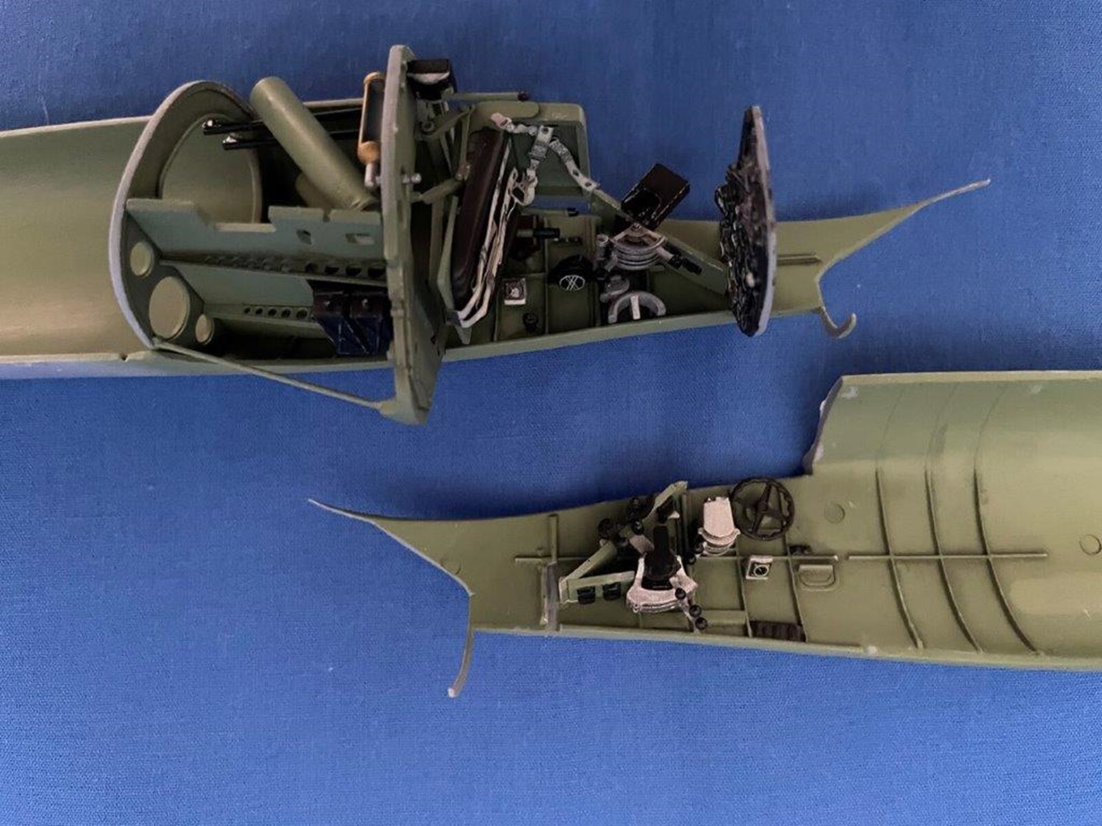
The cockpit was beautifully detailed and looked to be quite accurate. All the lever quadrants were “one piece” 3-D printed parts and replaced with what I thought were almost as nice multi part plastic kit items.
Two instrument panels were offered in the kit- one for an early built aircraft and one for a later built version. I chose the latter panel and painted and detailed it before applying the kit supplied decal instruments over the top. The instruction manual noted which of the four painting options used the early or late panel. The finished panel looked great and no aftermarket panel was needed. Unfortunately, a decal was not included for the prominent compass.
Two bulkheads were attached behind the cockpit. The slots they fit into were a little wide. Make sure the front one is vertical.
I turned my attention to the seat and the Eduard pre-painted photo etch Sutton harness set. I had already painted the seat parts interior green and the separate leather seat back black with a hint of brown. The Eduard belts were malleable and conformed easily to the seat. Special Hobby suggested adding the seat later in the build, which I did, but it would be easier to attach the seat to the bulkhead before closing the fuselage halves.
Closing the fuselage, I had to shave a little off the two rear bulkheads to achieve a better fit. The rest of the fuselage fit was not too bad.
The wings were complete top and bottom halves. The trailing edges of the wings, as well as the elevators and rudder, were quite thick. I did not attempt to thin them down. Oil coolers and radiators were attached to the inboard bottom wing sections. The grill representations were very well done and they looked great with a black wash. Quite large seam lines had to be removed from lattice interior wing framework to achieve a decent fit and look. Make sure all of these are vertical to achieve a good fit from the top and bottom wing halves.
The clear wing tip lights did not fit well at all. On top of that, I lost one. I used super glue to fill in the gaps. I fashioned the one I lost from a piece of plastic from clear sprue from the kit, shaping it to match the other side.
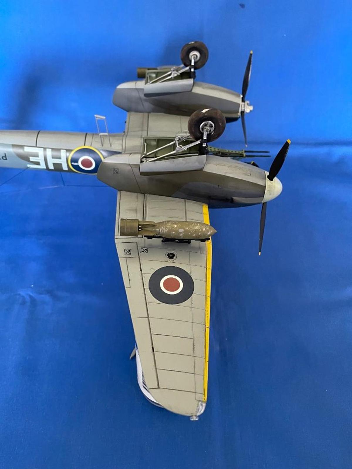
The engine nacelles came in two halves, plus a forward and rear bulkhead in the wheel wells. All parts fit well, except the front bulkhead. Two tabs that the landing gear legs mount to protruded too far forward and prevented the bulkhead seating into place. I carefully cut off the front part of the tabs and achieved a good fit.
The rear of the Rolls Royce Peregrin engine showed through into the wheel well and was glued to the front bulkhead.
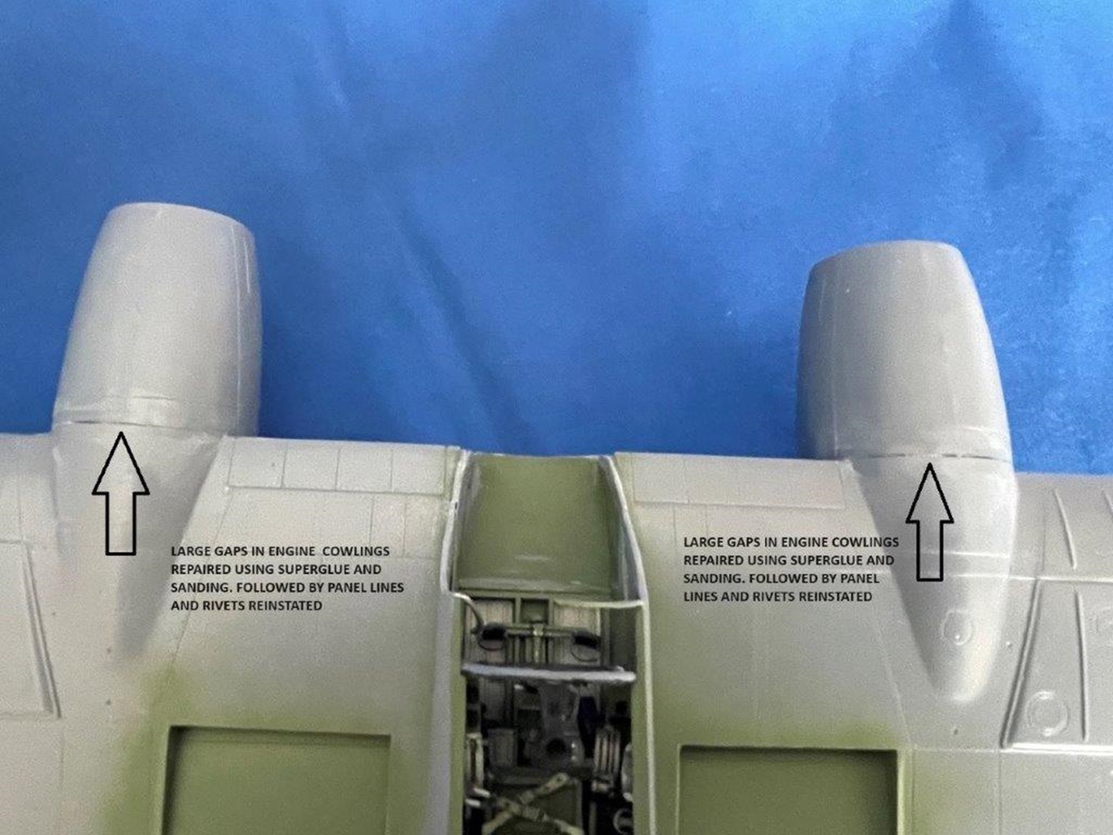
Mating the two nacelles to the wings I found the undersides fit very nicely. They only needed a little Tamiya putty to seal a few small gaps. The top joint was much worse and left sizable gaps that I filled with superglue and carefully sanded.
I assembled the propellors and spinners next. Each prop blade was separate but slotted into the propellor boss nicely. The boss’ were complete units that included the constant speed assemblies. I removed seam lines from one as it was nice enough to leave the spinner off to show this detail.
Before joining the wings and fuselage assemblies together, the cockpit floor, rubber pedals, bar and control rod were built onto the top of the wing, just like on the rear aircraft. Photo etch foot straps were curved and glued to the pedals. Two photo etch panels were located under the rudder pedal area and I found it easier to position them after the floor framework was in place.
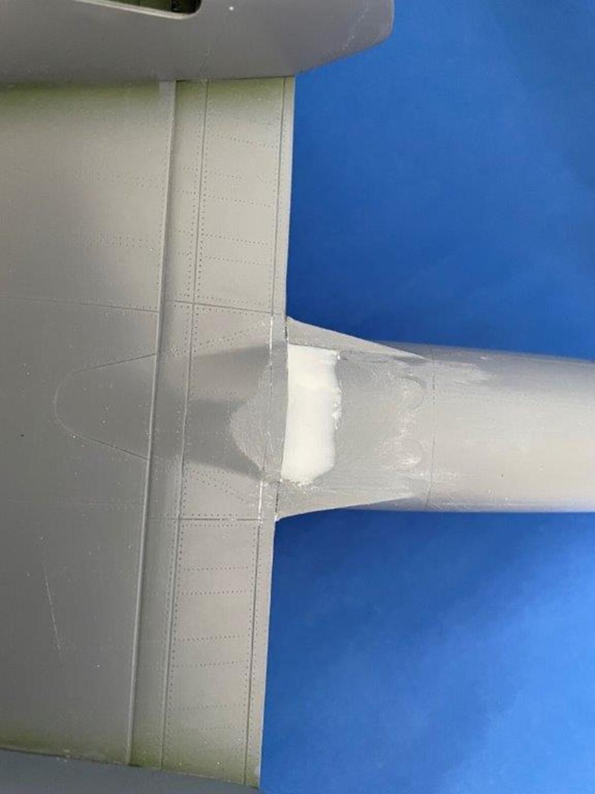
I had trouble fitting the rear of the wing to the fuselage and found the issue laid with the floor panel
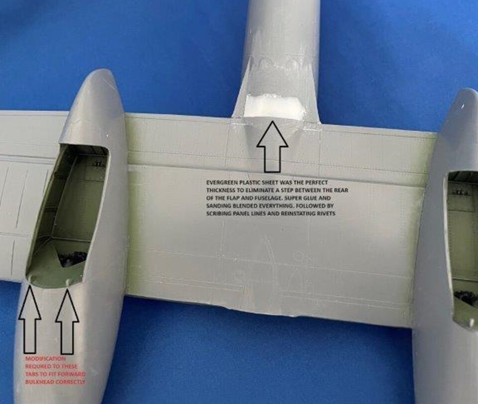
# G18 and the front bulkhead. I didn’t get the bulkhead quite straight and had to sand the back of the floor panel until it fit. Most of this panel was not visible as it was underneath the seat. Once this was completed, the wings attached to the fuselage very nicely except for a large step where the wing rear met the fuselage. I cut Evergreen plastic sheet to shape, super glued it in place and sanded the area flush. This worked well and I scribed in lost detail and rivets.
With the airframe completed, I glued the windscreen to the main fuselage and made sure each side lined up square. I had already masked and painted British interior green on the inside of the windscreen using the kit supplied canopy masks.
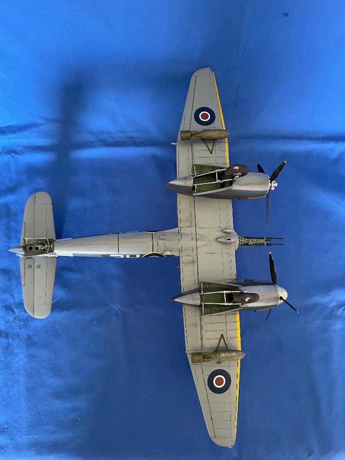
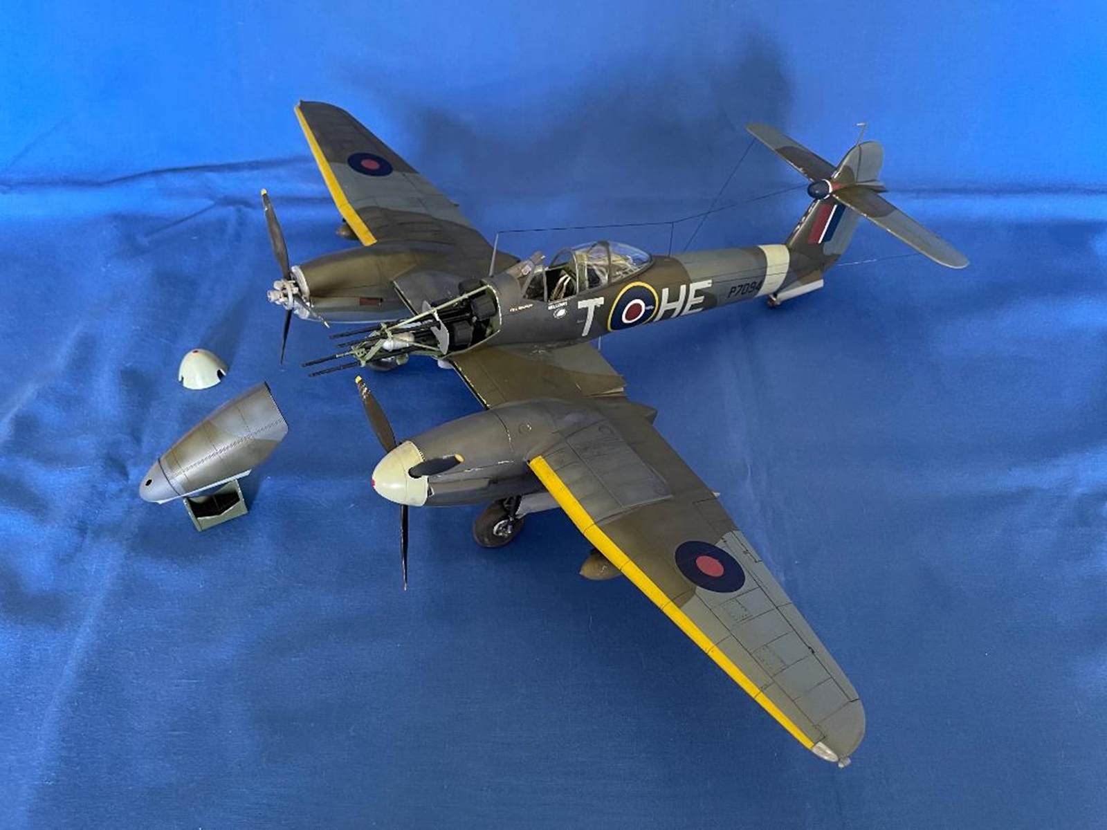
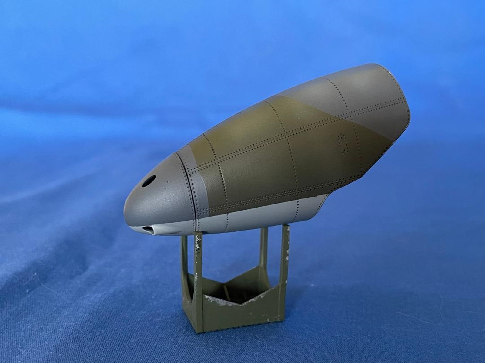
At this point, I painted the aircraft with a mix of Mr. Hobby Color and Tamiya acrylics. I chose the first of four schemes offered in dark green, ocean grey, and areas of a darker version of ocean grey over medium sea grey. The bullet fairing on the tail was painted “Blue Angels” blue.
I used the kit supplied masks for the inside and outside of the canopy and windscreen and they fit nicely. I did not use them to paint the main wheels as the masks would not conform around the deep curvature of the tire.
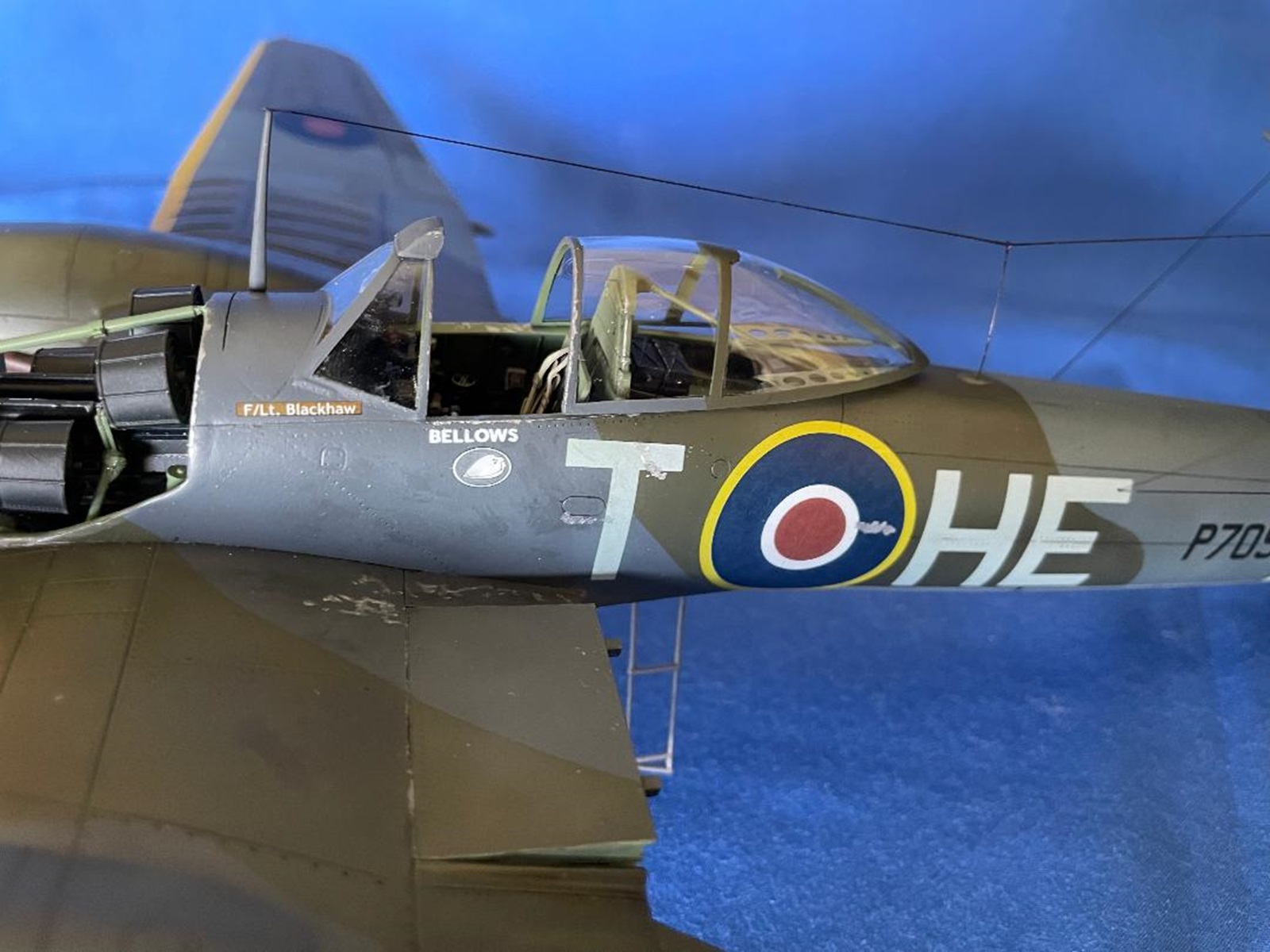
When done and gloss coated, I applied the kit decals. They were strong but thin. The clear film edges were quite wide and tended to fold over onto themselves. They were easy enough to unfold. Once in place, the decals “melted” into the panel lines and rivets beautifully with very little “silvering” underneath. The aircraft I was building, P7094, HE-T from No 263 Squadron, had small British, red, white and blue roundels painted on the propellor spinners, but I could not get the decals to conform to the curvature and left them off.
To stand the Whirlwind on her feet, I assembled the landing gear. For the main gear, I found it easier to start assembly of the retraction struts, arms and piston at the rear of the bay and work forward. This ensured I got the gear leg positioned at the correct angle at the front of the bay. The tail wheel leg was glued into its bay and was quite strong.
While the two-piece, plastic kit wheels were perfectly fine with flat spots and nice detail, the resin ones supplied were outstanding. No mention was made in the instruction manual about using the resin wheels, except at the beginning where the plastic sprue parts were “X'd” out.
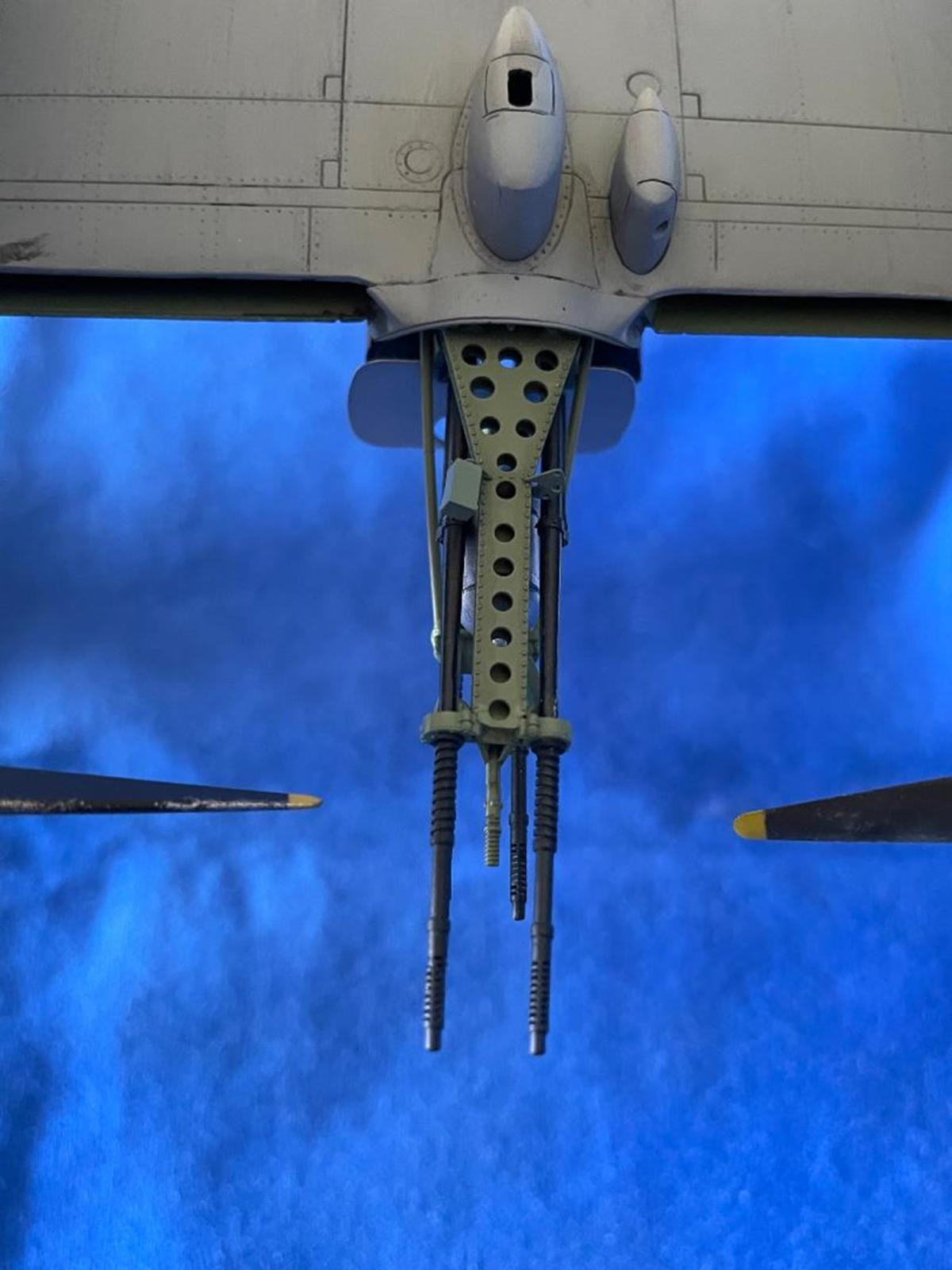
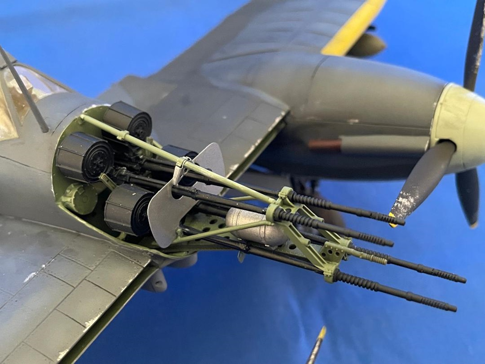
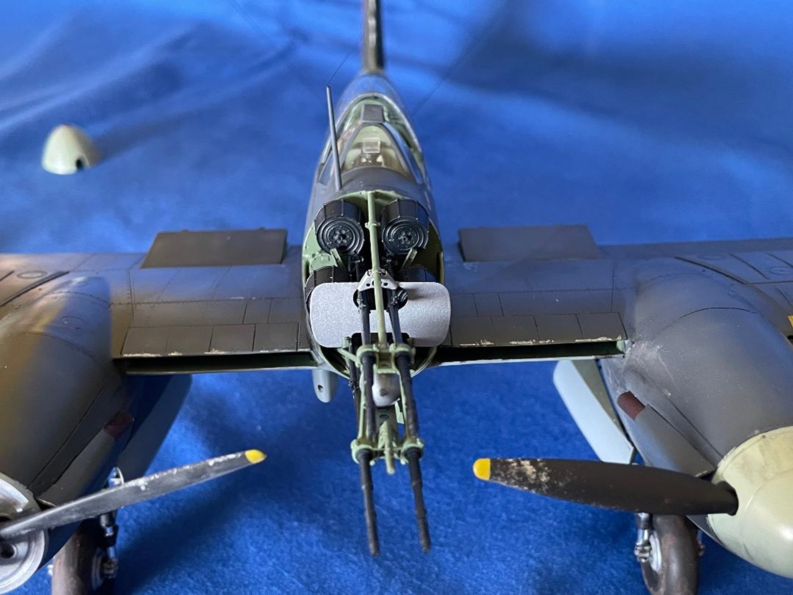
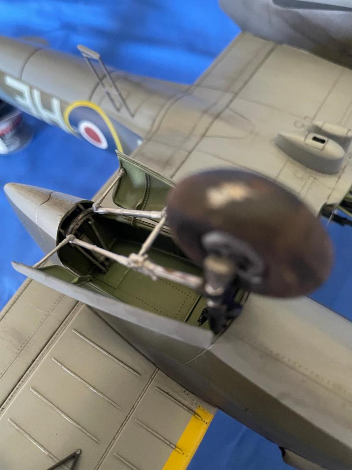
The crown jewel of this kit was the nose cannon assembly. All parts were 3-D printed, except for the rear bulkhead, cannon charging gas bottle and ammunition ejector shoots, that were resin, plus photo etch armor plates.
The 3-D printed parts were spectacular in finesse and detail. All the parts fit together quite nicely with just a little trimming needed. Care was needed, however, as they were quite brittle.
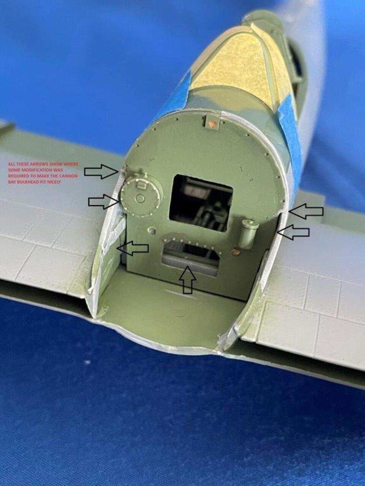
The instructions show mounting the cannon assembly to the bulkhead before mating the complete assembly to the aircraft nose. Don’t attach anything to the bulkhead until it has been trimmed to fit the front of the fuselage. The bulkhead simply did not fit the curved sides of the cowling profile. The bulkhead top did match the outer curvature of the fuselage perfectly. I spent a lot of time trimming and test fitting it to match the sides of the fuselage until I got a satisfactory result. Unfortunately, in my excitement of building the cannon assembly, I did glue it to the bulkhead before fairing that part to the fuselage, which then created issues and damage to the assembly. While I was able to reconstruct what broke or separated, something was off and I did not have enough clearance to attach the rear photo etch armor plate!
It was important to remove residual resin out of the mounting slots underneath the four resin cannons as they impeded the fit to the shell ejector shoots.
Once I had the bulkhead situated, the cannon and mounting framework slotted into the nose of the aircraft with some trimming of the frame side supports needed. Even with the problems I created, the end result was an awesome and deadly looking cannon arrangement!
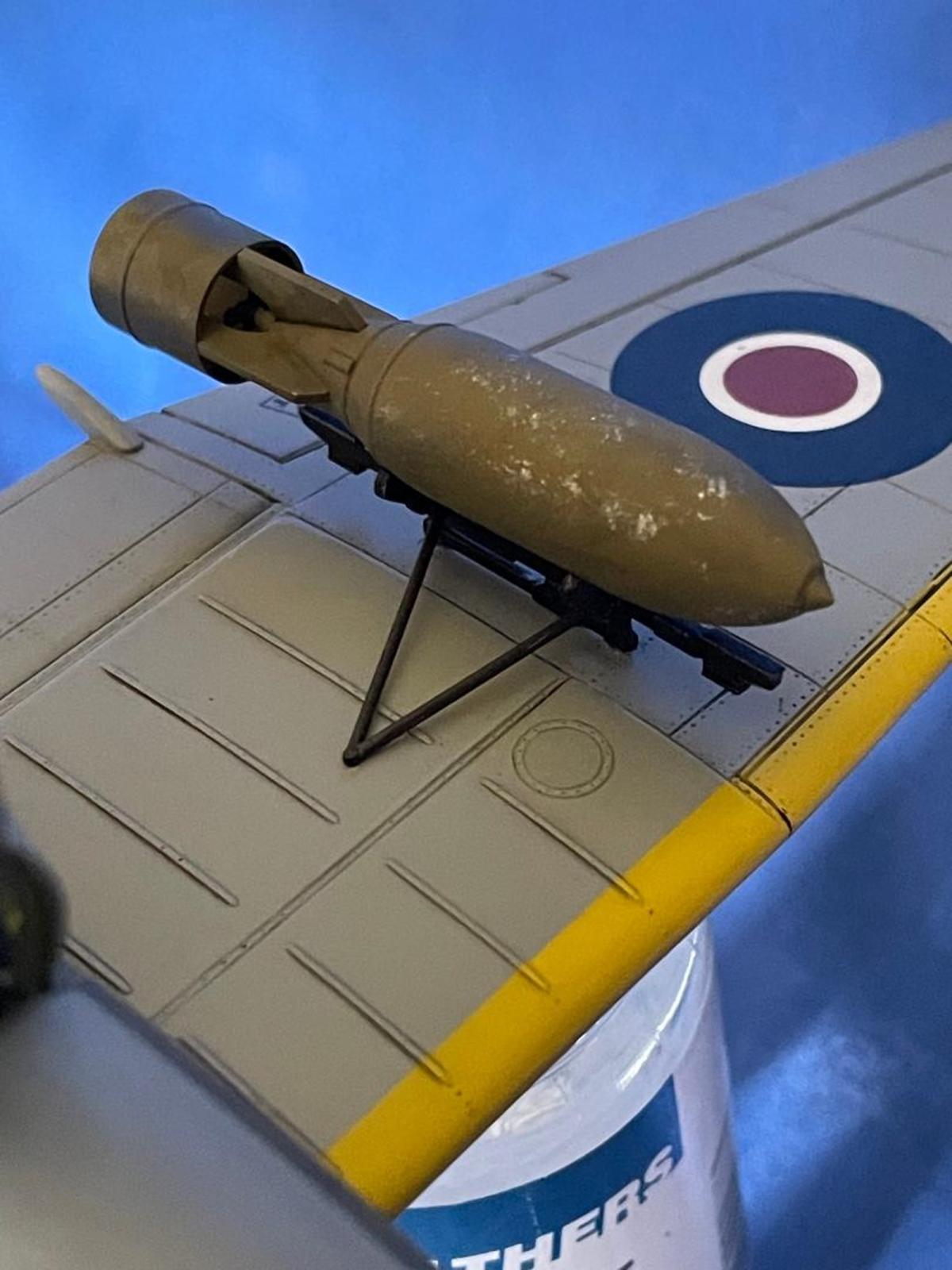
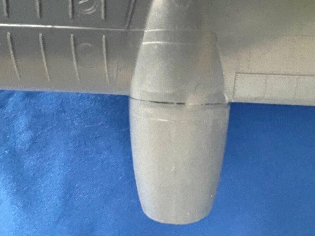
I decided to use the larger 1000 lb. bombs to furnish my “Whirleybomber”. I had predrilled mounting holes in the wings and glued the bomb rack plus sway bars in place. For the larger bomb, “V” shaped side strengthening bars were needed and attached to the sides of the racks and then to the wing underside. Their fit was a little ambiguous.
The last items to attach were the pitot tube mounted on the tip of the tail and an antenna in front of the windscreen. I drilled a hole in the base of the antennae and inserted wire for strength, as it was intended to be “butt” mounted to the fuselage. I then strung fishing line to facilitate antenna wires.
The Special Hobby Whirlwind was a fantastic model to build and really looked the part when it was completed. While the basic kit would not be out of reach for the average modeler, the inclusion of the Hi-Tech parts takes it to the experienced modeler category.
I would like to thank Special Hobby for offering the Whirlwind and to IPMS USA for trusting me with this review.
1000lb bomb
Whirlwind bottom
Whirlwind cannon assembly
Whirlwind Cannons
Whirlwind canopy
Whirlwind cockpit
Whirlwind engine cowling gap repair
cowling repair
Whirlwind front
Fuselage to wing gap repair
Gap repair
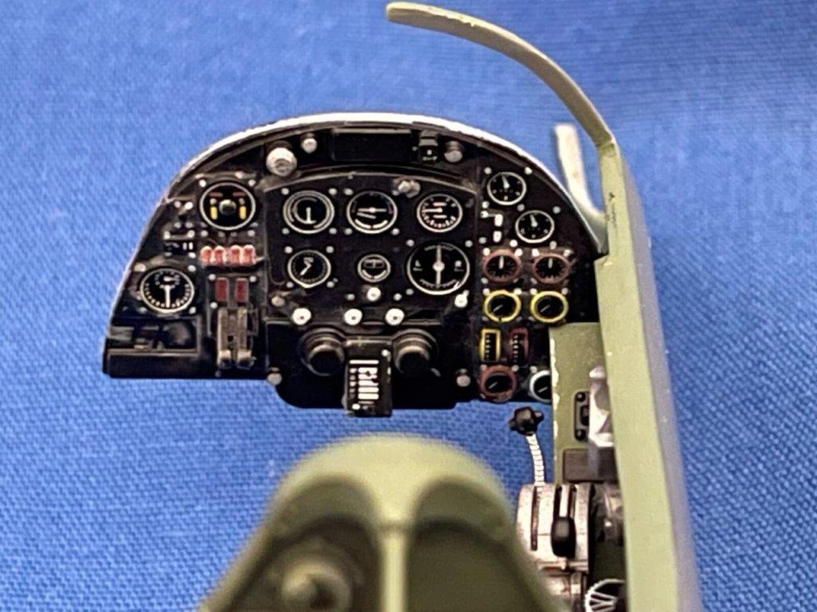
Whirlwind Instrument panel
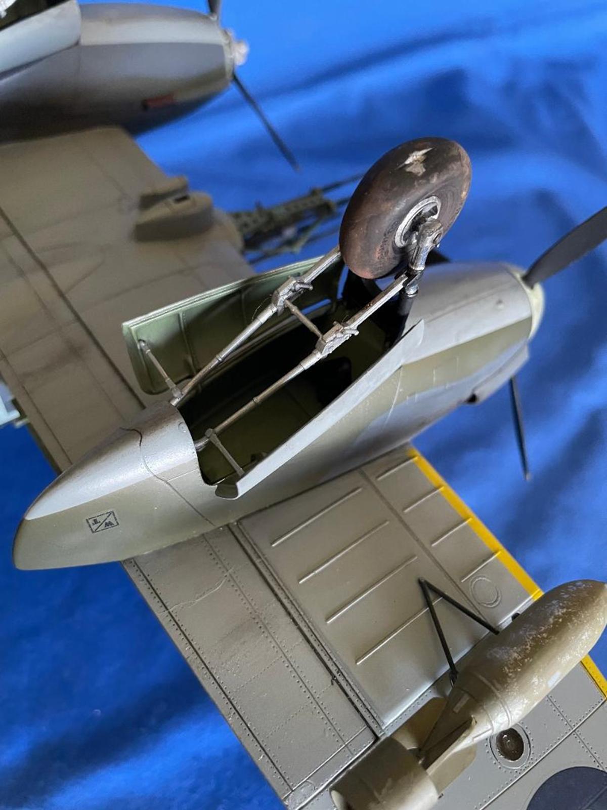
Whirlwind landing gear struts
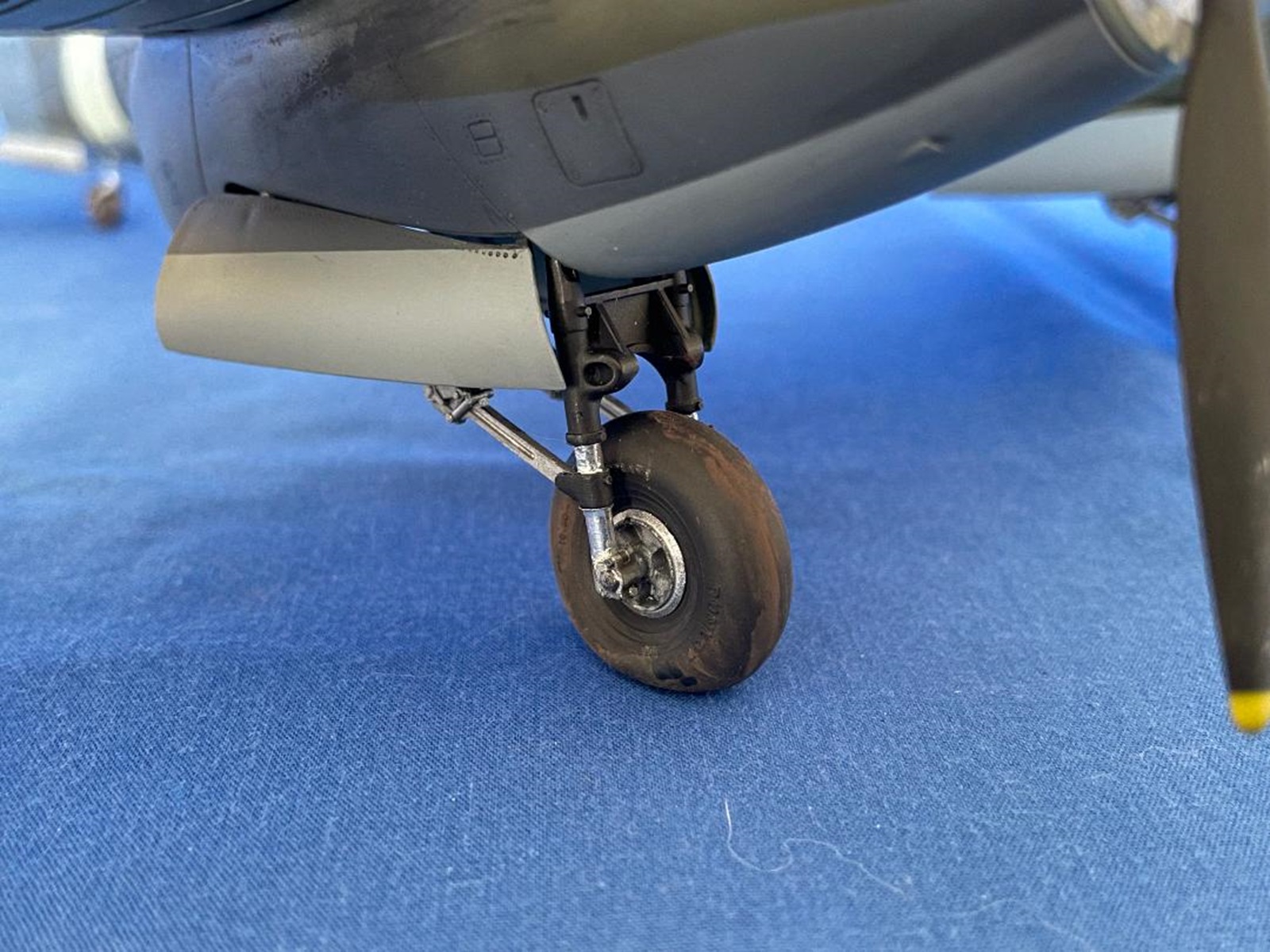
Landing Gear
Whirlwind left side
main wheel well
Bulkhead work
Bulkhead work 2
Nose cone stand 3d printed
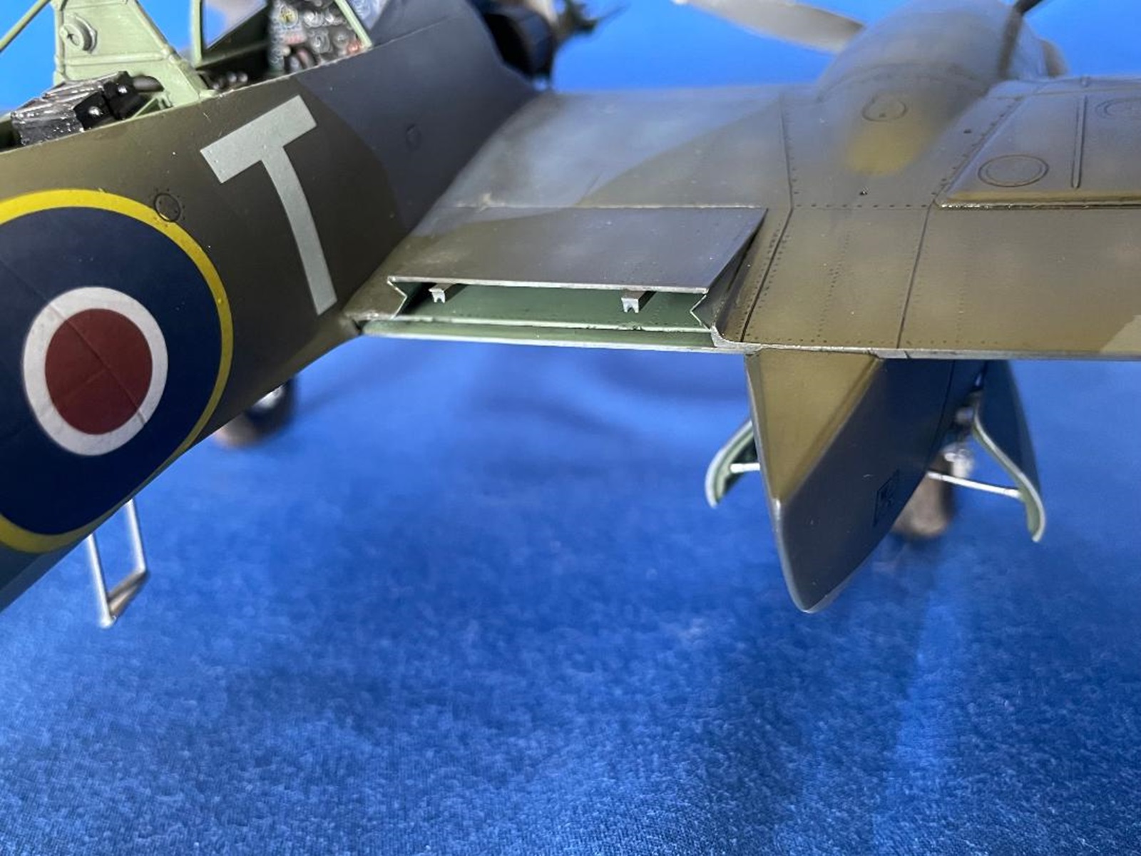
whirlwind cooler door
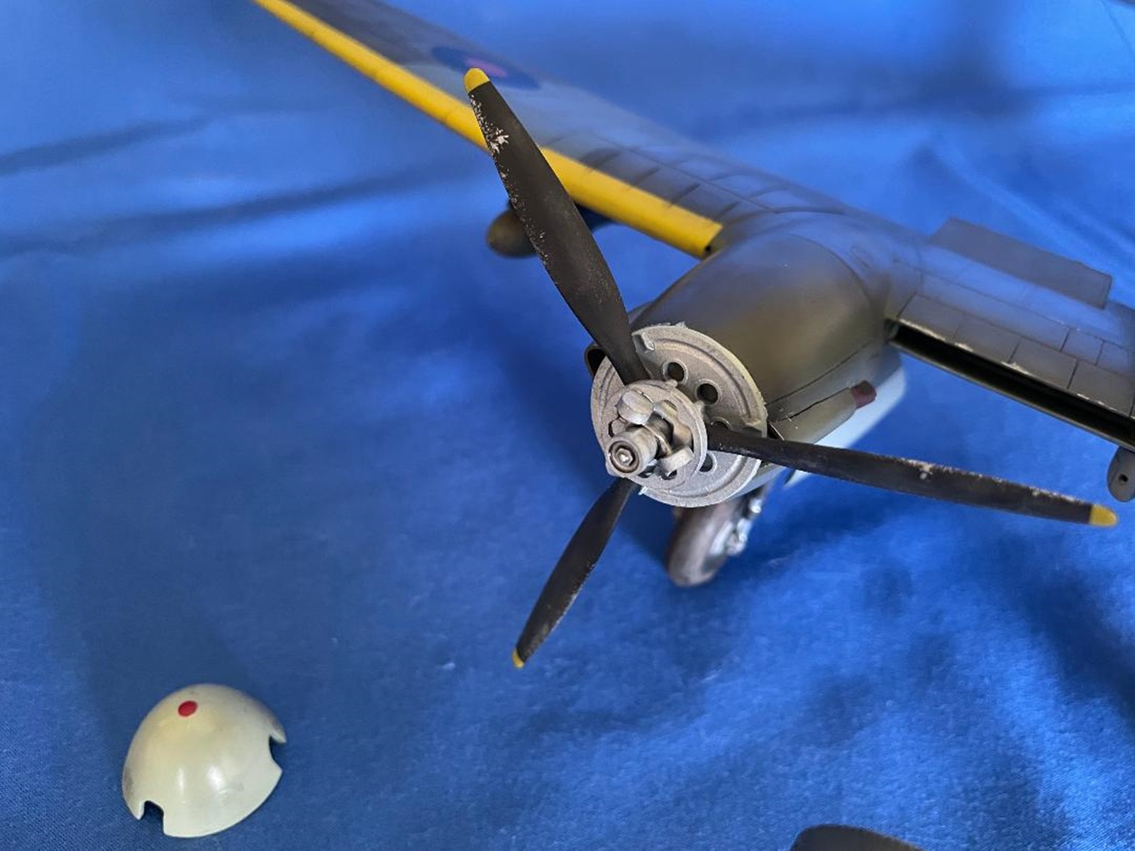
Whirlwind propeller boss
Whirlwind rear view
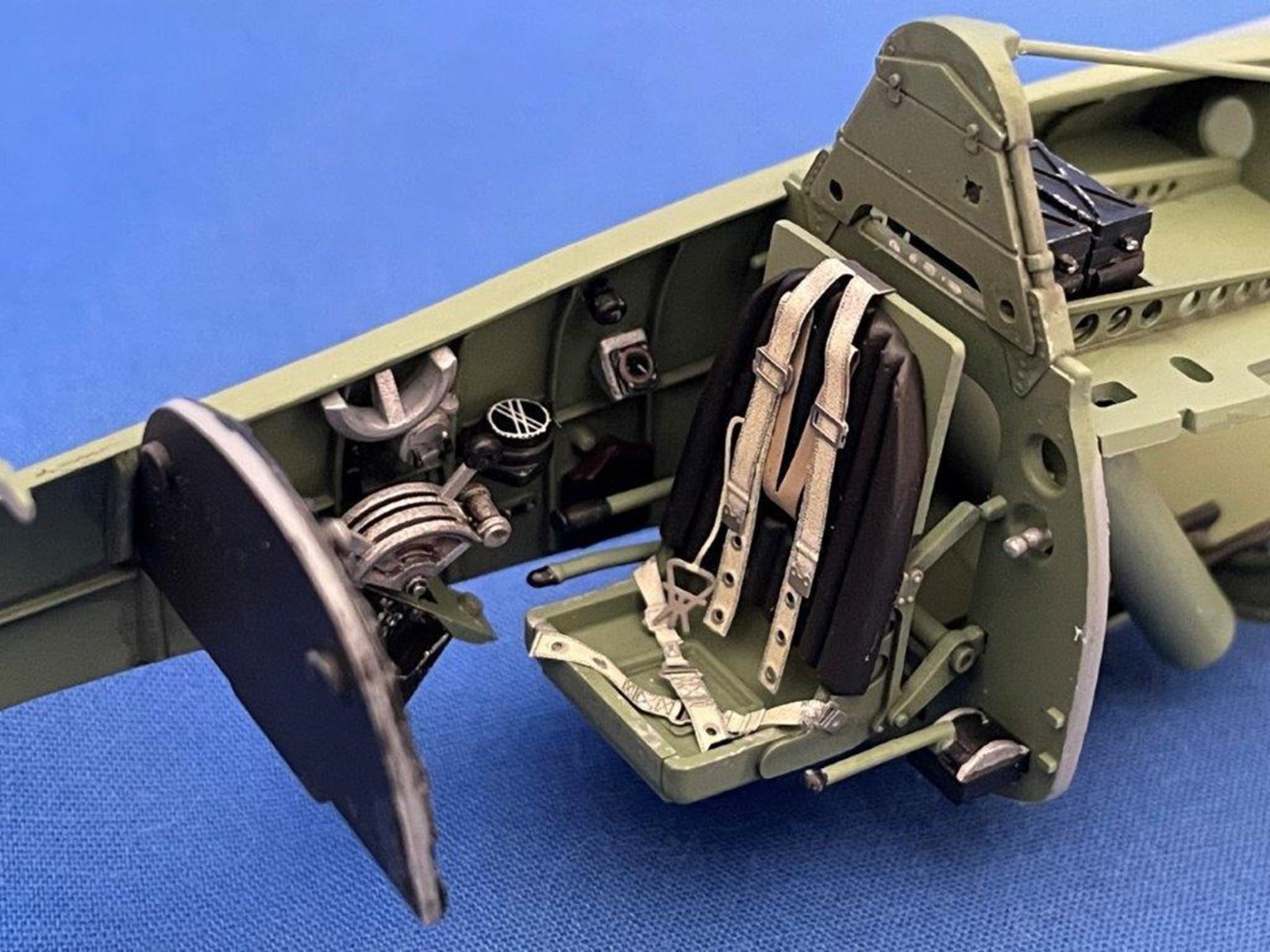
whirlwind seat and belts
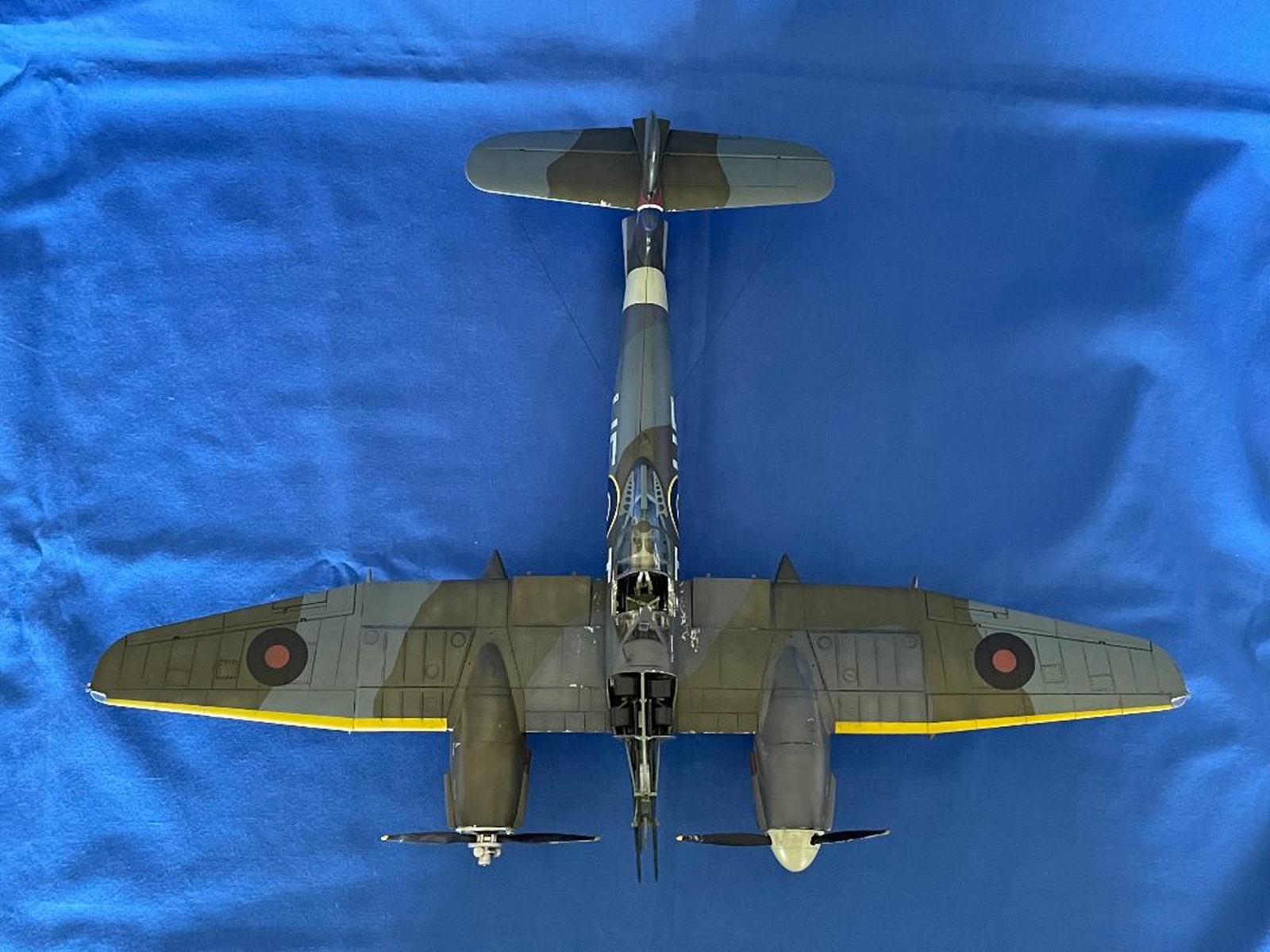
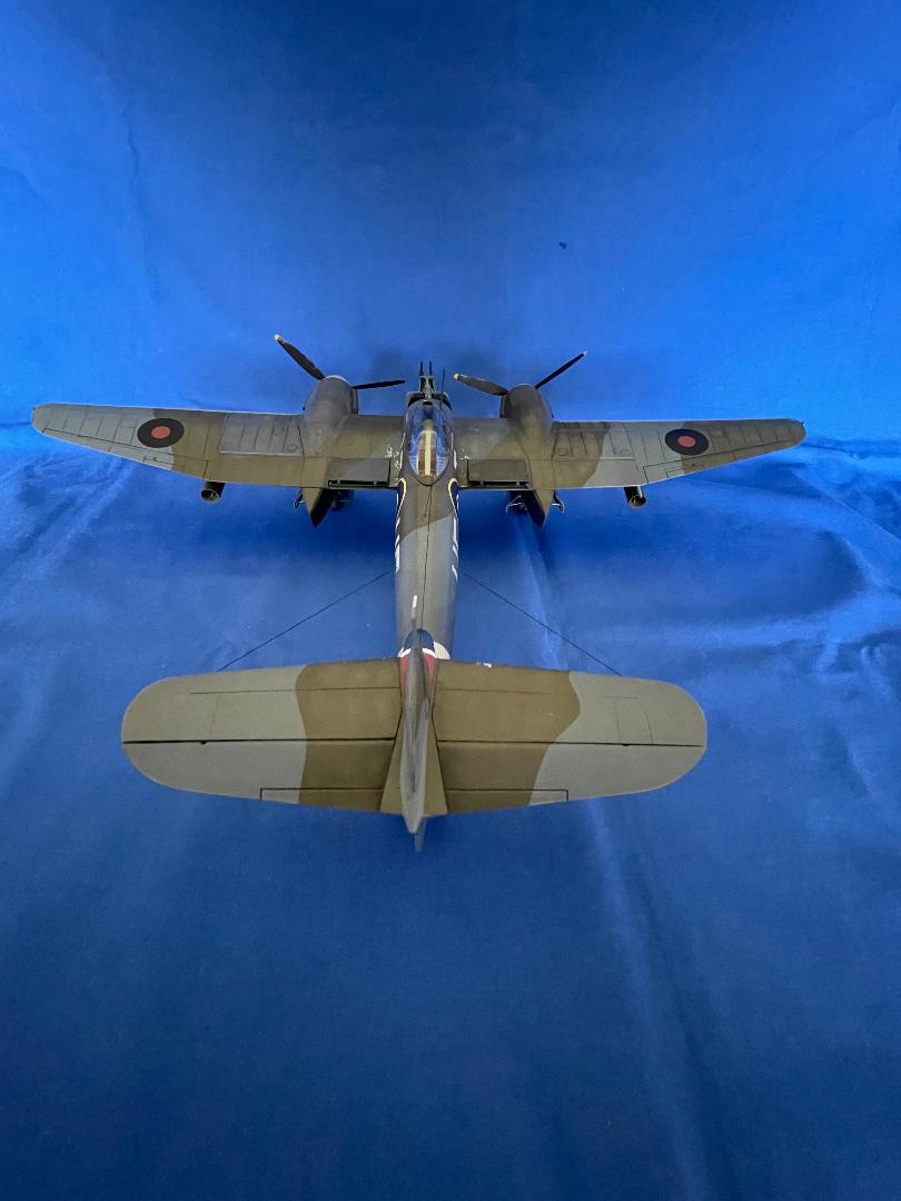
whirlwind top view
Comments
Add new comment
This site is protected by reCAPTCHA and the Google Privacy Policy and Terms of Service apply.
Similar Reviews