
USMC F/A 18D
History
The F/A-18D is a two seat variant of the early McDonald Douglas Hornet. The rear seat of this variation is configured to allow a Marine Corps naval flight officer to function as the system and weapons officer similar to that of the F-15E Strike Eagle rear seater. In this roll there are no flight controls situated in the rear cockpit. With the US Marine Corp the F/A-18D serves primarily as a night attack bomber and forward air controller.
These modern D models are the result of a block upgrades in 1987 and 1989 which gave the Hornet the capacity to carry new missiles and air-to-ground weapons. Now fitted with forward looking infrared, night vision goggles, multi function color displays and moving maps the Hornet is capable to strike anytime of day or weather deep behind enemy lines.
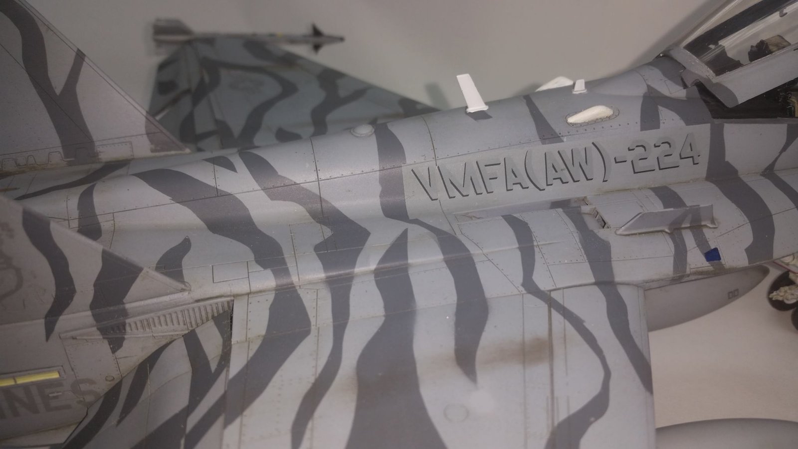
VMFA(AW)-224 “The Bengals” received the F/A-18D in February 1993 transitioning from the Vietnam era A-6 Intruder. From April to September of 1994 the squadron deployed its new Hornets to Aviano, Italy in support of operations over Bosnia, Herzegovina. They flew 1150 sorties and putting in 1159 flight hours. In September of 2005 the Bengals again deployed to Aviano to support NATO operations.
In January of 2005 with numerous upgrades to their aircraft including the availability to deploy J-DAMs,VMFA(AW)-224 deployed to Assad airbase in Iraq in support of Operation Iraqi Freedom. During this deployment they flew 2500 sorties with 7000 hours of flight time in direct support of US Marines and coalition forces. Over 65,225 pounds of ordinance were exhausted.
Choosing this version of this aircraft to model was easy for me as I have a long affinity for US Marine Corp aircraft and God willing I will eventually build them all. Not only did I wish to build this subject but specifically to build this airframe in this particularly striking Bengal Tiger paint scheme. Here comes the dilemma in that these markings were delivered in Academy’s first release of the F/A-18D which I owned but I am reviewing the more recent release. After probing the contents of the two boxes I determined that other than the decals supplied by Academy there is no significant difference between the 2005 release and the 2014 issue that I am to review.
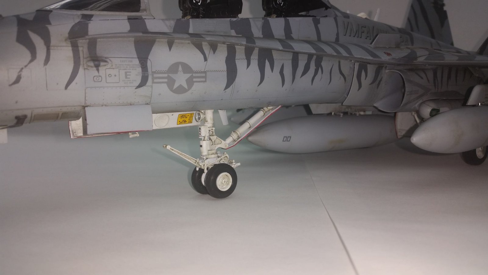
One note to be covered before I start is I was cautioned to use the SAC or G-Factor cast metal landing gear in place of the Academy gear. This admonishment came directly from the Reviewer Corp captain who himself had built this kit, and was aware of the tendency of the kit supplied landing gear to sag under its own weight. More on the landing gear in a bit.
In the Box
Once you open the Academy box you are simply over come by the number of parts enclosed. This is a huge kit.
Together with this are the following:
In a separately enclosed box you will find;
- 4 Rubber tires individually wrapped.
- 37 Crystal clear parts, 35 on one spure and 2 individually wrapped canopies.
- 3 Cast metal landing gear strut inserts.
- 1 Screw Driver.
- 5 Small Screws individually wrapped.
- 1 Styrene plastic dark gray Nose cone
- 801 Finely molded parts on 20 separate spure all in a dark gray. Each and every runner is individually wrapped as to prevent scratches. Relief and rivet detail is all engraved. Fully half of these parts are for the abundance of modern ordinance that are included with this kit.
Deep under all the spure runners you will find a 40 page instruction booklet and two decal sheets. One decal sheet is 14 ½” by 10” and includes the markings for three individual aircraft. The second decal sheet is 6 ¾” by 9 ½” and will mark all of the enclosed weaponry.
Surprisingly there is no Photo Etch.
There are many building options to this aircraft and it helps to early decide how you would like to display your model.
- Wings extended or folded.
- Flaps set to 0, 20, 30 or 45 degrees.
- Rudder turned or straight.
- Elevator position able.
- Exhaust open or constricted.
- Nose open with radar exposed or closed.
- Landing hook up or down.
- Boarding ladder up or extended.
- Canopy open or closed.
- Air brake open or closed.
- Varity of ordinance to be included.
- AIM-9L Sidewinder Practice, Inert, or Live
- AIM-7F/M Sparrow
- AIM-120 AMRAAM
- MK. 82 500lb Bomb w/wo fuse extender or retarder
- GBU-31 J-DAM
- GBU-10 Paveway II
- GBU-24 Paveway III
- AGM-84D Harpoon/ -84E SLAM
- AGM-65E Maverick
- AGM-88 HARM
- All with appropriate launchers
- Varity of targeting pods to be installed.
- AN/ASQ-173 LDT/SCAM pod
- AN/AAR-50 TINS pod
- FLIR
- And three 330 Gallon External Fuel tanks
The huge aircraft decal sheet gives you options to mark three distinct US Marine Corp aircraft.
- BuNo 165686 VMFA (AW)-242 “Bats” DT-01 USMC Iwakuni, Japan 2010-2012 with Black tails
- BuNo 164955 VMFA (AW)-242 “Bats” DT-00 USMC Iwakuni, Japan 2012 Line jet
- BuNo 165411 VMFA (AW)-225 “Vikings” DT-00 USMC Miramar, California 2012 Line jet
Similarly the weapons decal sheet gives you options to make your ordinance either live, practice or inert. Besides having many decal options there are abundant spare decals available for possible decaling errors. Enclosed you will also find decals for the herewith 1/32 scale crew members.
The instruction sheet is rather a small book and it will behoove you to become familiar with its layout. At 40 pages you will find a rather intense color and paint index on the first page. Through out, the instructions are in both in English and Korean with simple number call outs for the parts and complex symbols for the directives. I found the directions easy to follow once I was familiar with the symbols used but made color index cheat sheets for each open page to eliminate the desire to flip back to the front.
The sequence of the build is typical to any other modern aircraft with the only major variation being between pages 25 to 28 where you given the instructions on how to build the aircraft with the wings folded. Pages 29 to 33 are dedicated to the external stores. Pages 34 to 38 are for painting and decaling instructions for figures, ordinance and the three variations of the aircraft. Page 39 and 40 are a parts location diagram.
The Build
Having studied the instructions and determined which options and variants of the F/A-18D to build, I put all my other many projects away and commence to start this project on November 23, 2014. A variety of paints and cements would be used including but not limited to Tamiya cement, Tamiya acrylic paint, Testors Model Master acrylic paint, Testors lacquer gloss coat, Testors lacquer flat coat, Alclad II metallic paints, JB Weld two part adhesive, Tamiya weathering master powders, MIG premixed washes, AV acrylic putty, and Bondo 817 putty.
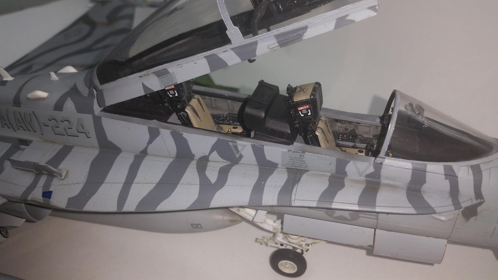
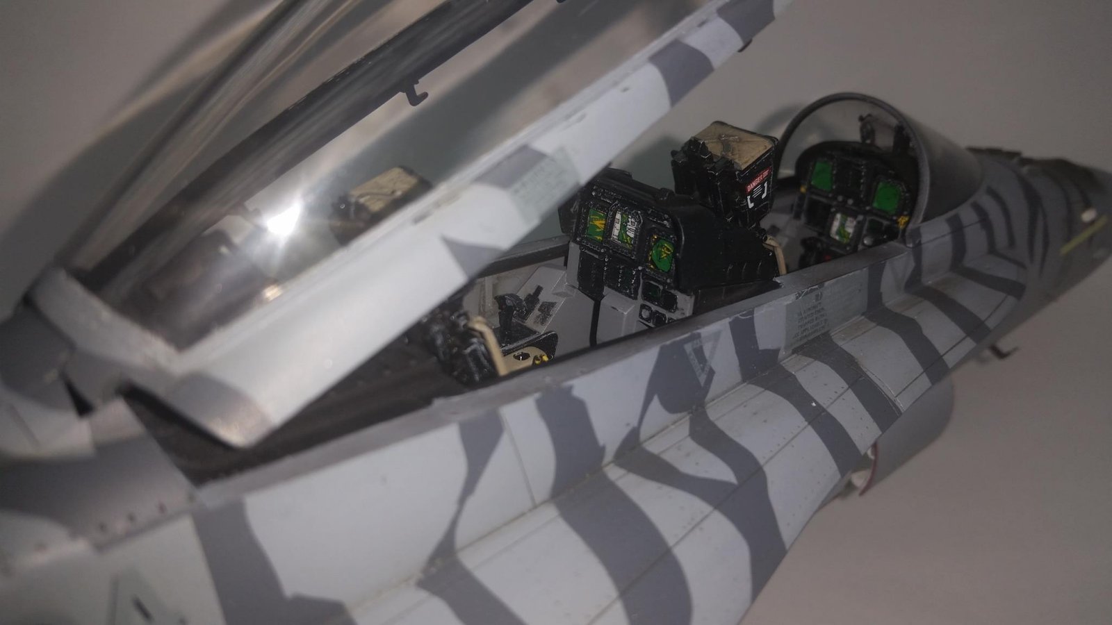
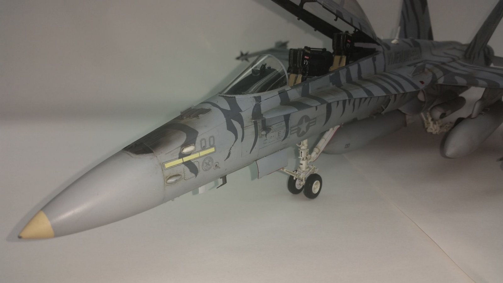
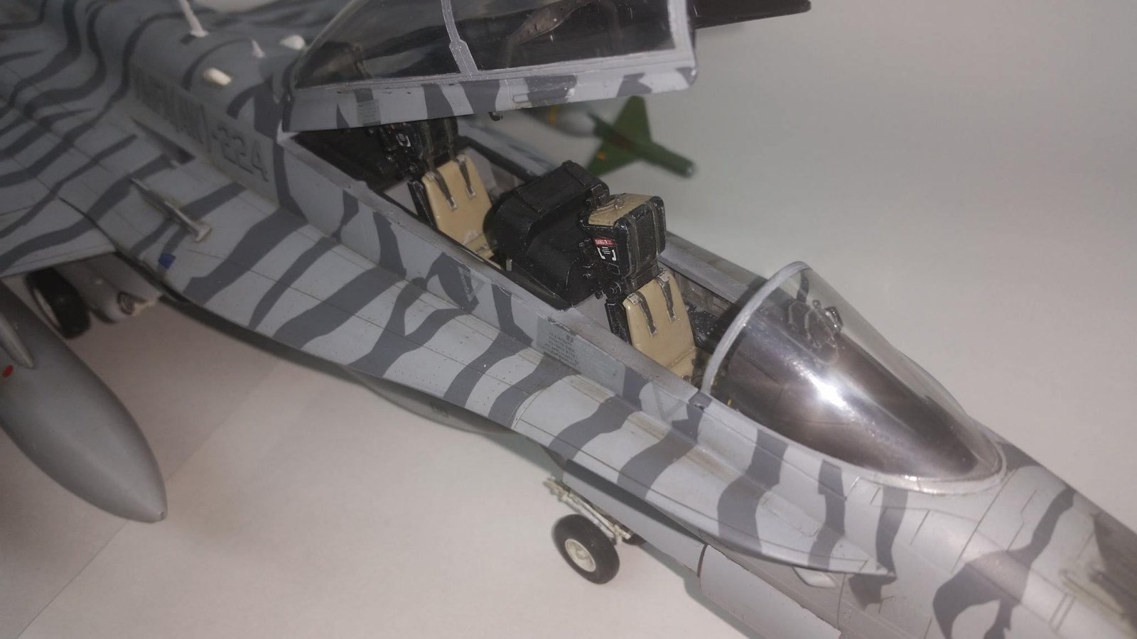
Typical of most modern aircraft models the construction starts with the cockpit, in particular the ejection seats. Each seat consists of 14 parts which although accurate have less than the required detail of kits of this scale. On my next Academy F/A-18 I may choose to replace these seats with resin components. The rest of the cockpit is very well detailed and have meticulous painting instructions for the instrument panels. The multifunction displays are replicated by decals on plastic inserted to the rear of the panels and then covered in clear plastic. This cockpit looks fantastic with a little care in painting, some light washes and a through drybrushing.
Assembly now moves forward to the front wheel well and landing gear. Again more decals and attention to painting fine points and you have a beautiful subassembly without any tricks or hard work. There is an option for plastic wheels or rubber; I choose the rubber so that they could be left off till the final assembly.
With your cockpit and front wheel well mated you now find yourself detail painting the insides of the cockpit walls and assembling the forward section of the aircraft. This subassembly can be set aside as you move to step 7/8.
Through the building process I found the fit of all the many subassemblies to be of the highest of caliber. There were no sink holes in any of the parts and very few ejector pin marks. Absolutely no flash what so ever. Only the engine intake trunks parts A5, A6, and A7 had blemishes that need to be sanded and filled more than once. I counted a total of 12 injector pin marks to fill and sand. Once happy with the intakes seams I used the latex paint pour method for a fine intake trunk interior.
One area which takes particular attention was the fitting of the upper and lower fuselage parts around the intake trucks on page 7 at step 8. Be extra careful here and you will avoid the major misalignment and a ton of putty later. Parts A1 and A2 go together at this point with screws but it is really easy to misalign some portions. As the instructions state use some tape to temporarily align the part and check your fit.
Prior to step nine you will need to determine if you will be building the plane with the wings folded. Very quickly this kit is beginning to take shape at this point.
On page 9 at step 11 again take your time with some dry fitting in order to get the splinter plates and intakes to align well with the fuselage. There are lots of little parts here to get lined up correctly for the acceptable look.
The greatest area of possible improvement in this kit is at page 10 steps 12, the attachment of parts B40/18 and B39/17. Where the winglets attached to the wing just above the intake there can be some major gaps/filling opportunities. I discussed this prior with a few friends who had built this kit and all were of the same opinion that super care needs to be used here to avoid major misplacement of the parts. Too low and there is a very visible seam above adjacent to the cockpit and too high and both a visible seam and huge gap to fill on the bottom. After much dry fitting I was able to maintain the alignment on the top surface with only some small putty work and rescribing to do below.
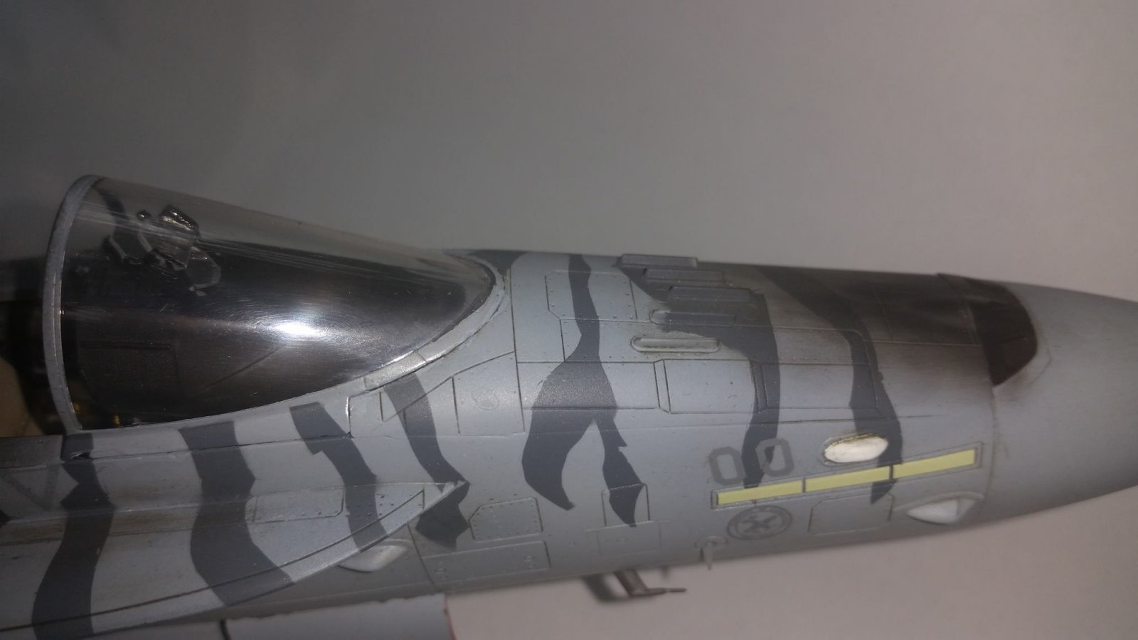
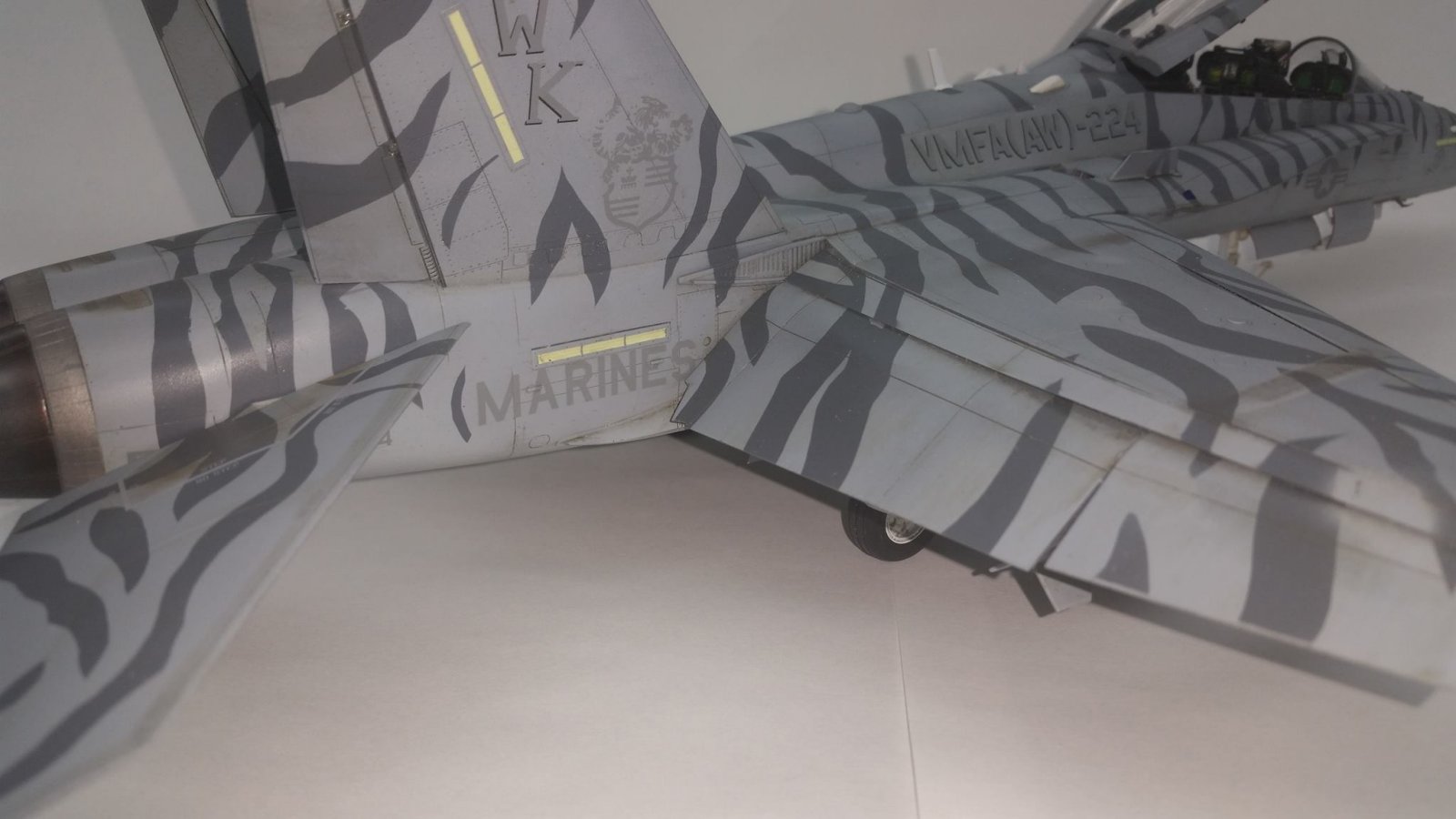
Do to the important paint scheme I choose to only temporarily mount the flaps as directed in step 14. Parts D25/24, F24, F25, and F41 were permanently attached to set the flaps at 30 degrees down but the flaps were only tacked on to facilitate masking and painting. Once the template for the painting was outlined on the flaps I removed them for further painting, clear coating and weathering. I used the same sequence for the rudders in step 18. The elevators were painted separate also and attached after weathering.
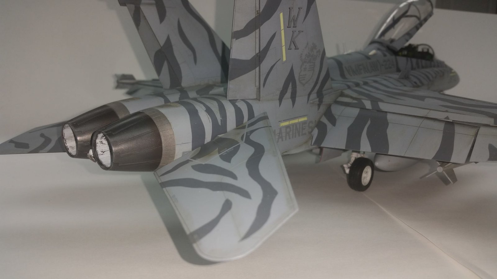
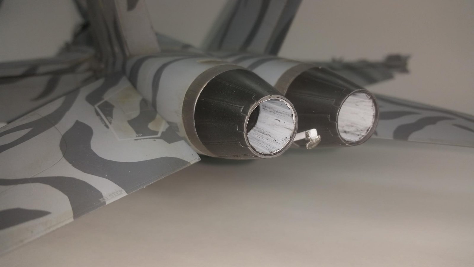
Step 19 will have you mounting the exhaust cones; in my opinion just a little too early. I left my exhaust cones off till the final stages of construction to facilitate the ease of painting the cones and the complicated paint scheme. Around step 20 to 22 don’t forget to add a little nose weight to the aircraft. I chose to super glue a few 00 buck shot to the tip of the radome nose prior to installation at this stage. The instruction give no hint as to when or how much weight to add, I just knew past this step would be too late. Wish I had build my radar nose cone open (choose not to as the aircraft would be with ordnance) as there is an incredibly comprehensive radar system. Nine decals and nine parts make up this the radar assembly which is begging for super detailing.
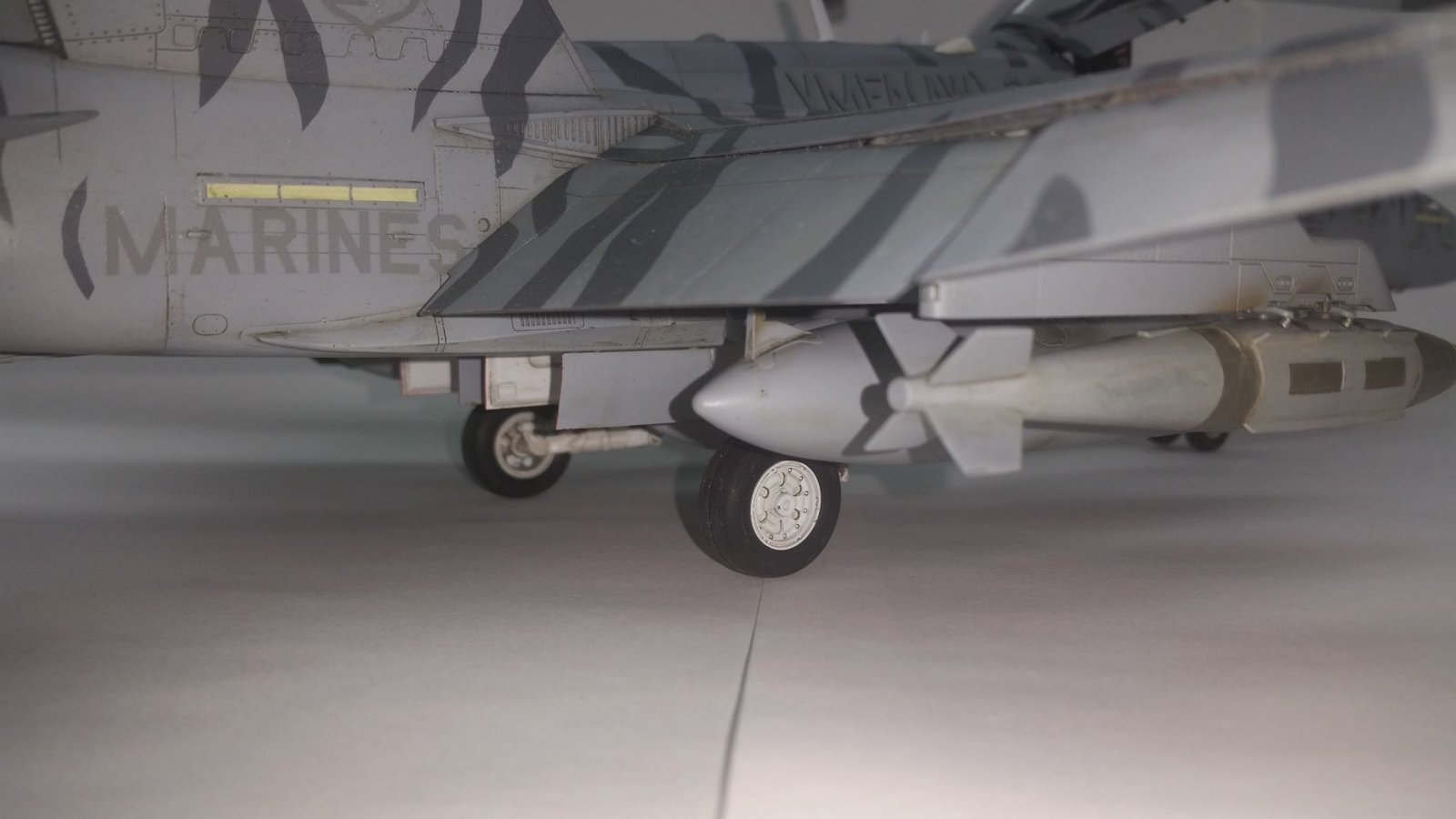
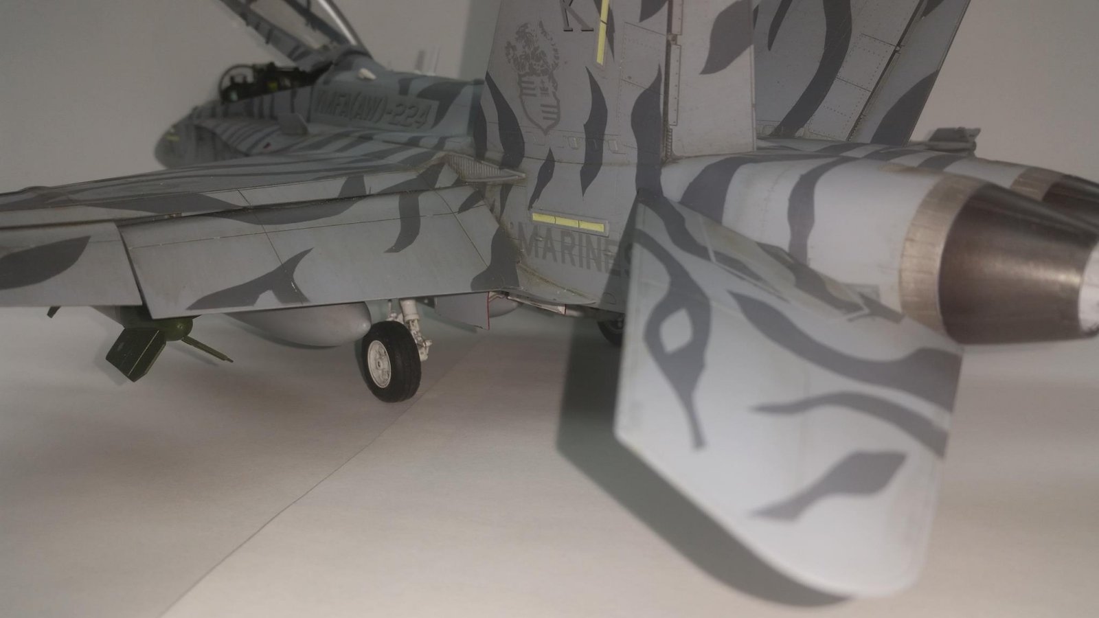
Up next is the main landing gear assembly sequence where I choose to replace the kit gear with the cast brass gear from G-Factor. The G-Factor gear will use many of you plastic parts from the kit to finish correctly including the wheels and tires. Again I choose to leave the rubber tires off to final assembly. I mounted the gear to the kit using J-B Weld two part epoxy. This allows a strong plastic to metal adhesion as well as time to work with the gear alignment prior to the glue setting up. Gear and gear door assembly continues for five pages with detailed painting and decaling guild. Once finished with all the weight on the struts, there was no sag to the G-Factor landing gear.
The canopy was cemented to the airframe using Testors cement for clear parts and then masked using an Eduard paint mask and Gunze Liquid Mask. This allowed me to leave the canopy on from painting to final weathering.
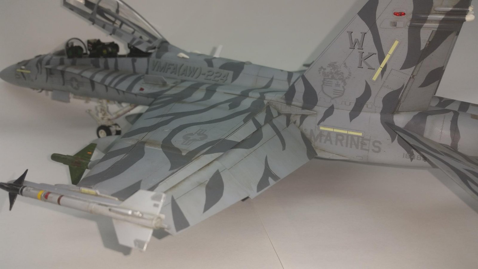
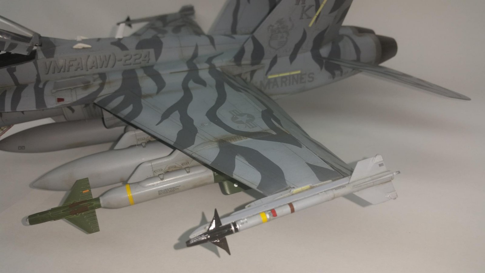
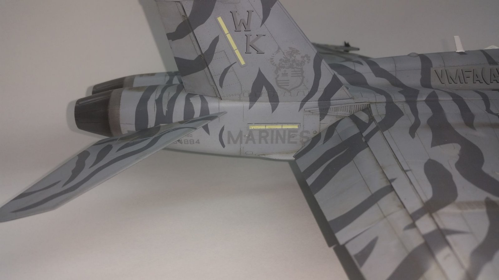
I came about the paint scheme in the 2005 issue of the Academy F/A-18D and found it rather a challenge. It was replicated by blowing up the painting instructions from the 2005 kit to the proper measurements of 1/32 scale. These instructions were duplicated for every angle on the plane surface. Once satisfied that I had every angle of the paint scheme covered I transferred these template drawings to sheets of Tamiya tape laid on wax paper. Carefully I cut the templates and transferred them to the model. I worked a small section of the kit at time until all the sections were tied together with the paint scheme. Numerous touch ups were needed to complete the paint design but well worth the effort.
Prior to final assembly painting the multi color paint scheme was finished up and multiple coats of Testors gloss lacquer were applied to seal the finish with a high gloss. Kit supplied decals went on well with one exception. I was using the decal sheet from the 2005 release of this kit for the proper VMFA-224 Bengels markings and there was some aging/cracking to the decals. Prior to using a critical decal I discovered this and gave the decals a thin coat of Micro Scale Superfilm sprayed by airbrush. There was no issue with the decals used from the 2014 issue of the kit. All the decals conformed well to a little help of Micro Set and Sol. Once thoroughly decaled the kit was again sealed with Testors Gloss.
At this point I began the weathering process. Working in small sections at a time I applied a pin wash of MIG interior panel wash. The wash helped tie all the various components and panels together giving a needed relief to the huge scale aircraft. Once finished with the wash and happy with all the color modulation I gave the Hornet a nice misting coat of Testors Flat lacquer.
Beginning at step 28 through step 35 are the final assembly sequences including tail hook, boarding ladder, heads up display, canopy, antennas, speed brake, weapon pylons, and navigation lights. Regarding the boarding ladder, tricky little turkey, I ended up not using mine because I was unable to satisfactorily get it built. A small jig would be handy for assembling these ladders. Steps 36 through 45 are dedicate to those who choose to build the F/A-18 with the wings in the folded position.
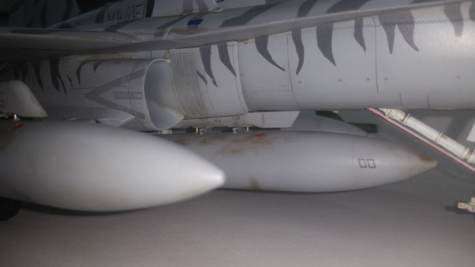
Step 46 through 51 shows how to assemble and paint the multitude of ordinance and pods available for this kit. With such a variety available I found it necessary to build them all then determine how I wish to arm my Hornet. I placed AIM-9 L/M on outboard station 1 and 9, 330 gallon fuel tanks on stations 2, 5 and 8, J-DAM on station 7 and GBU-24 on station 3. I rounded out the load with AN/AAs-38 FLIR on station 4 with AN/AAR-50 TINS pod on station 6.
Once I had worked my way through all the final assembly sequence and arrived at a point where I was happy with the final product I began to do some final weathering using the Tamiya weathering master powders. Streaks, soot, stains and panel color modulations were easily obtained using these “cosmetic” like powders.
Provided in the kit are 27 parts on two trees which allow you to build four different figures. There are two variations of pilot figures, one seated and one climbing the boarding ladder. The pilots come with multiple head/helmet options including night vision goggles. Also included is one Navy Catapult Officer in launch position and one Marine Ground Crew. There is a detailed guild showing how to paint the figures and add the various markings included in decal form.
My VMFA-224 (AW) F/A-18D Bengal Hornet took me 181 hours to build. Could have been less had I not choose the challenging paint scheme and to build the entire ordinance collection. There are really no major stumbling blocks in this kit just steps that take extra caution. The instructions are well planned and for the most part easy to follow.
I thank MRC Academy Models for the opportunity to build and review this amazing aircraft and IPMS Review Corps for their patience and guidance with this project.
Footnote; My build took 1st place in 1/32 Jet at the IPMS Las Vegas Best of the West Southern California Nevada Regional. Pretty pleased.

Comments
Add new comment
This site is protected by reCAPTCHA and the Google Privacy Policy and Terms of Service apply.
Similar Reviews