
Tiran 4 Late Type
Background
The most important Soviet tank design of the early post WW2 period was the T-54/T-55 series of tanks, and these tanks were exported in large numbers to Soviet client states including Syria and Egypt. The 1967 and 1973 Arab/Israeli wars were disastrous for the combined Arab armies, and Israeli forces captured hundreds of intact examples of the T-54/55 tanks. Not wishing to look a gift horse in the mouth, the Israeli military developed a procurement program designed to put these captured tanks back into Israeli service. Over the years the Israeli Defense Forces (IDF) fielded the Tiran 1, 2, 4 and 5. The Tiran 1 was an unmodified T-54, and the Tiran 2 was an unmodified T-55. The Tiran 4 was a modified T-54 with new jerry can and stowage boxes added to the exterior of the vehicle, as well as a change to the loader’s hatch, and the addition of turret mounted exterior machineguns. The Tiran 5 was the same modification program as the Tiran 4, but for the T-55 tank. As the IDF introduced more modern tanks into its arsenal, some “spare” Tirans found their way into the hands of Israel’s local allies, such as the “South Lebanese Army” based as the name implies, in southern Lebanon.
What’s in the Academy Box
- 87 sprues of injection molded light gray plastic parts
- 3 sprues of injection clear parts
- 1 sheet of waterslide decals with 4 marking options
- 1 sheet of photo-etched brass parts
- An instruction manual, with 20 pages of black and white assembly drawings covering 104 assembly steps plus a 4-page set of color and marking instructions, and a two-page sprue layout diagram
This is the fourth “T-54” kit in MiniArt’s “Interior Kit” range that I have had the great pleasure to review. And I will say up front that these kits aren’t for the faint of heart. The quality of the parts included in each kit is phenomenal, being beautifully detailed and well molded with little if any flash, few ejection pin marks, and no sink marks. However, there are over a thousand parts, including over 100 photo-etched parts, some of them incredibly small, in the Tiran 4 kit under review here. I can state in total honesty that I had a blast building this kit, but I can not in good conscience recommend it to anyone other than a modeler who has a number of 1/35th scale armor models under their belt, and who has no fear of photo-etched parts and super glue. You also need to be a meticulous builder of kits, because the 1000+ parts need to be very carefully and accurately assembled into a relatively small space. If you aren’t careful, and glue parts together that aren’t correctly lined up or in the correct spot, you will experience heartache. However, if you are up for a challenge, keep reading!
This kit of the Tiran 4 has a near-complete interior, both hull, and turret. About the only thing missing in the hull (I’m not sure why) is the transmission and cooling systems. Assembly Steps 1 through 8 consists of the engine’s construction, numbering about 40 parts. About the only thing missing is the ignition harness. Following the construction of the engine, comes the start of the lower hull suspension assembly. Spend some time studying the assembly diagrams, as there are a lot of parts to line up correctly, and if you want the suspension to “work”, you had better get it right!
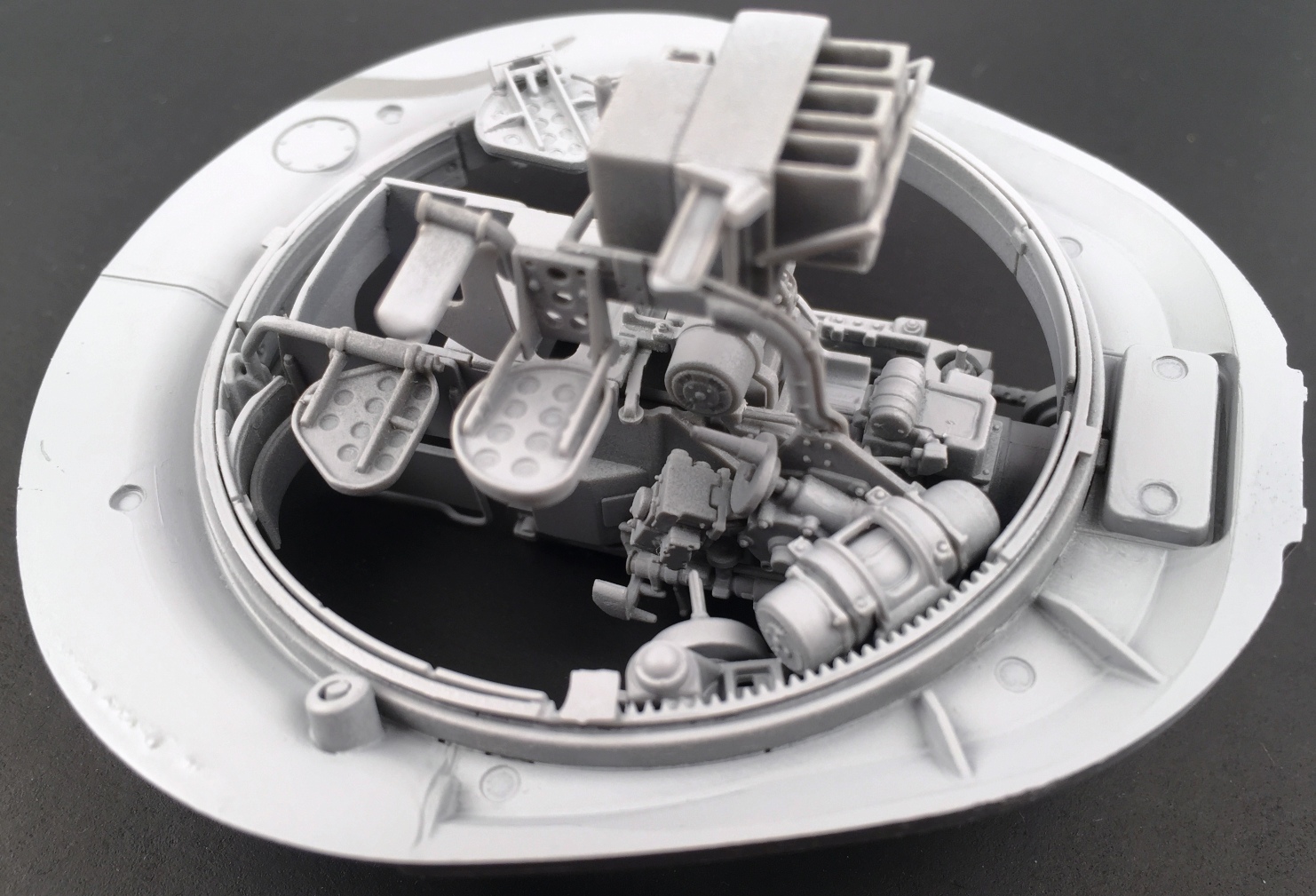
The interior of the hull is quite “busy” with a driver’s seat and brake pedal, gear leavers etc. The driver’s seat alone has 6 parts, two of them are PE. Make sure as you work your way through the instructions that you keep a sharp eye out for instructions telling you to drill out flashed over holes for the attachment of parts later on in the instruction manual. One small complaint I have with MiniArt’s super detailed kits is that some of the parts have what I consider excessive sprue attachment points and the parts that do always seem to be super fine/delicate parts where there is a high risk of damage to the parts as you attempt to separate them from the sprue. I highly recommend purchasing a pair of the “God Hand” brand sprue cutters from Japan. These aren’t cheap, but they are an extremely well-manufactured precision set of snips and give you the most chance of getting small delicate parts off the sprue without damage. As an example of what I am talking about in Step 17 of the hull interior assembly sequences, there is part B3, which has 15 (!!!) sprue attachment points. Each must be carefully cleaned up, all the while trying to avoid shattering the part.
Steps 20 and 21 involve the construction and installation of the hull shell munitions storage lockers: lots of very nice shells, which if you examine their location in the storage locker by dry fitting them, you will note that it is possible to fit them in such a way that only one of the two seam lines that run their length needs removing. By careful placement, you can avoid having to do the other, and it won’t be seen once construction is finished. As you progress through the assembly and installation of the hull interior components, you will notice that it is getting more and more crowded, and you realize why it is so important to check and double check the instructions before gluing parts in place. Making a small mistake in the positioning of a part in Step 10 can lead to issues much later in Step 25, so be vigilant!
Steps 28 through 33 deals with the installation of the road wheels, drive sprockets and idler wheels. It would be most useful if you could find a set of 1/35th scale plans that show the “sit” of the road wheels so that you get the suspension ride height correctly worked out. I would advise gluing the road wheels in positions 1 and 5 first and making sure the hull is level on these four wheels. I used a simple system of rectangular wood blocks to ensure the road wheels lined up evenly front to rear, and one side to the other, with some low-tension clamps. Once these first four wheels were installed and the glue fully set, I installed the remaining wheels, three per hull side. Make sure you don’t glue part Kd2 in place initially, in Step 31-33. This is the idler mount and allowing it to pivot freely in its mount will assist with getting the tracks to more easily be in alignment. The tracks, assembled in Step 45, are individual link, and are exquisitely well detailed, although with 4 sprue attachment points per link, are a little time consuming to clean up and assemble. But well worth it IMHO.
Step 36: part Te6, engine access plate on the rear deck of the upper hull has some great weld detail on the hinges, just one example of the finesse of the parts in this lovely kit. In Step 38 I had my one disaster with a piece being damaged in my attempt to get it off the sprue, part T2. Thankfully it snapped in a manner that allowed me to carefully and successfully glue it together without any major harm to the project. Also, in Step 38 is PE part PE45, which was so small that I gave up trying to pick it up and successfully glue it in place. There are a small number of the PE parts that had me thinking this way, but none of them were missed when I finished up the project. And speaking of PE, Step 41 – 43 has the modeler installing four PE mesh screens on the rear of the rear hull deck. I would recommend leaving these aside for later. I painted them separately, first applying a coat of Tamiya grey rattle can primer to the exterior surface only. I held the PE parts with self-locking tweezers, and if the primer gummed up the mesh, I had a Q-tip dipped in lacquer thinner ready to wipe the underside of the PE (the side without the primer), and this removed any excess without damaging the primed side. Likewise, when I went to apply the color coat.
Step 45: the assembly of the individual track lines, listed as 90 per side in the MiniArt instructions. The fidelity of detail on these tracks is amazing, down to casting numbers being clearly visible. Each link is attached to the sprue by four points, as mentioned earlier, so it is a bit tedious cleaning these up. Just do say 20 links at a time, over multiple building sessions. I then made a simple assembly jig out of two rectangular but equal lengths of basswood. At each end of the lengths of wood, I put some shims of Evergreen plastic, the width of the track guide horns. I then placed small clamps to hold each end of the wooden blocks together. This left a trench down the middle of the blocks, and I put the track links, guide horn down, onto the trench, and applied glue. Excess Tamiya thin solvent glue on the wood just evaporates. This method allowed for rapid lining up of track links. I glued 45 links together in on long length, using the slower curing Tamiya plastic cement. These were allowed to sit for a short while, before I glued them to the underneath of the front road wheel and then back under the remaining roadwheels, and up and around the rear drive sprocket. The process was repeated on the other side of the kit. The glue was allowed to set overnight. The process of gluing the track links together was repeated, and this time the links were first glued to the tracks already installed, from the front roadwheel, and up and around the idler wheel (whose arm was still not glued in place), and then the upper track sag was created, before the track run was glued to the initial track run at the drive sprocket end. You may need to add a link, or remove a link, from the recommended number of 90. Create the track sag you are after, and when you are happy, glue the idler arm solidly in place. Repeat for the other side.
Lastly for the hull components, is the fenders/mudguards. There are lots of storage bins, and fuel cells along each side of the hull, and the fuel lines that link the cells together are also included. Lots of little PE parts are incorporated into the fenders for tool storage tie down etc. Step 49 – 55. Then jump ahead in the assembly diagrams, to Steps 101 – 103, for the installation of more fuel cell plumbing. Make sure these Steps are completed BEFORE you glue the fenders to the hull, otherwise you won’t be able to see clearly to install the fuel lines.
Now we are on to the construction of the turret. The interior of the turret is festooned with intricate detail, and once again I must caution that it is imperative to closely study the instructions so that you get the parts glued to their precise location point, to avoid finding out that later parts now won’t fit because earlier parts were slightly misaligned. There are big parts, medium sized parts, small parts and teeny tiny parts. All are amazingly detailed, all fit precisely if only you pay careful attention to the instructions. About the only thing missing from all these parts is some electrical cabling, and if you happen to have some good reference photos of the interior of a T-54/Tiran 4 turret, feel free to install these. I won’t go into detail about which areas of the turret interior are present/detailed because simply put: all or most of it. You will have no issues leaving the turret hatches open on this kit with or without a crewman in the opening. Let the IPMS judges shine their little flashlights into the openings, and all they will see is a mass of detail!
On to the exterior of the turret, and this area too is festooned with well-detailed parts such as jerry cans with PE holders, spare track links, grab handles etc. Plastic and PE parts, some of the latter extremely tiny, all add up to an amazing assortment of bits and pieces. The Israelis added extra turret top mounted machineguns to the Tiran 4, and MiniArt offers an array to chose from depending on which vehicle you are depicting from the color and marking schemes. So, make sure you check which MGs go with which vehicle, or check your reference material carefully. The machinegun parts themselves are beautifully rendered, utilizing plastic and PE parts. There was a little flash blocking the gun tubes on one of my MG parts, which required a little cleanup, and I drilled out the barrel tips with an appropriately sized drill bit. Each MG has an ammunition box with nicely detailed strings of bullets.
Once the turret is assembled, you can attach the fenders to the hull, and then the turret to the hull. The tow cable shackles are separate parts, and I utilized appropriately sized Eureka twisted copper wire cable material for the vehicle tow cables.
MiniArt provides four color and marking options for this kit, though they aren’t very descriptive:
- Israeli Defense Forces, 1970’s overall sand color
- Israeli Defense Forces training unit, early 1980’s overall sand color
- South Lebanon Army, Operation “Peace for Galilee” June – September 1982 two tone blue gray/gray
- South Lebanon Army, 1980’s overall blue gray
MiniArt provides a small decal sheet with the kit, though the markings for each vehicle are very simple, especially those for the SLA vehicles. The decals are well printed and commendably thin. The decals proved rather fragile, so be careful when removing them from their backing sheet. Gently slide them into position. On my first attempt, I slid a small decal to the edge of the backing paper and attempted to pick it off the sheet with a pair of tweezers. The decal snapped into two parts. So, slide them into position!
I chose the overall Blue Gray colored South Lebanese Army 1980’s scheme, which has literally only two small number plate decals. If you are in the market for a nice book on the Tiran in Lebanese service, I can recommend “Tiran in Lebanese Wars” by Samer Kassis, published by Ammo by MIG, the model paint manufacturer. Otherwise, go out and look on the internet to find color photos of these vehicles. I used Tamiya’s acrylic XF-18 Medium Blue together with Tamiya XF-20 Medium Gray to come up with my “South Lebanese Army Blue Gray” color. Thinned with Tamiya’s proprietary thinner. To lighten the base color just add some white.
The model was first primed with my favorite primer, Tamiya’s superb lacquer “Fine Surface Primer: Light Grey” item # 87064. I applied a few light coats to the model which provided a uniform surface for the acrylic color coats. This was allowed to cure for three or four days until it was good and hard. The model was painted in three subassemblies: hull, turret, and main gun barrel. This made for easier handling. The Tamiya acrylic blue-gray paint mixture was airbrushed over the entire model in a series of two or three light applications, slowly building up the color. After being allowed to dry a few hours, the base color was lightened, and then panel fade was applied. The subassemblies were then left overnight to cure. I then picked out a suitable track color, Vallejo “Track Color”, and painted the tracks. Then when this had dried overnight, I took Vallejo “Dark Rubber” and painted the rubber rims of the road wheels. I took this same Dark Rubber paint, and utilizing a small piece of sponge, proceeded to “chip” the paint of the vehicle. I then took the Track Color and used it to add a difference color chipping effect and worked particularly hard around the area of the engine exhaust on the left rear fender.
The model was then airbrushed with Tamiya X-22 Gloss Clear and left to cure overnight. The two decals were applied and left to dry overnight, and then some light coats of X-22 Gloss Clear sprayed over the decals to seal them. Another 24 hours to allow the clear coats to securely cure, then it is time for the “wash” to highlight the detail. A suitable color of dark brown oil paint was put on a piece of cardboard from a thick-sided box, to wick off the excess linseed oil, and then the paint was mixed up with some odorless mineral spirits. The mixture was applied with a small tipped brush and then left to dry overnight. A number of Q-tips were dipped in odorless mineral spirits, and the excess “wash” was removed from the model. Once I was satisfied with the look of the “wash”, I left the model alone for three days so that the oil wash dried thoroughly. I then airbrushed all the subassemblies with my favorite matt clear coat, AK Interactive’s Ultra Matt Varnish. This was then left to cure for 24 hours. I then got out my set of Lifecolor acrylic Rust “Washes”, and added a little rust around the engine exhaust, the tow cables, and a few other random places, just to add a little color to the project. Finally, I mixed up some Tamiya XF-57 Buff, suitably thinned, and applied some heavy road dust around the road wheels, lower hull, and front and rear of the hull, and then a thinner general dusting over the entire model subassemblies.
I then put the turret atop the hull and I was done.
To summarize: this kit is NOT for those with weak backbones

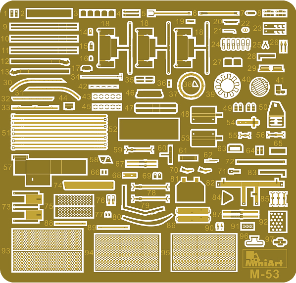
Photoetch sheet
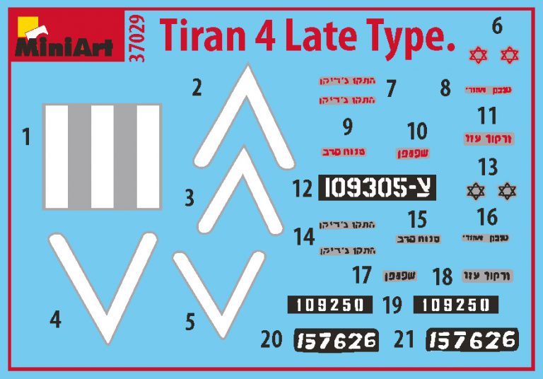
Decal sheet
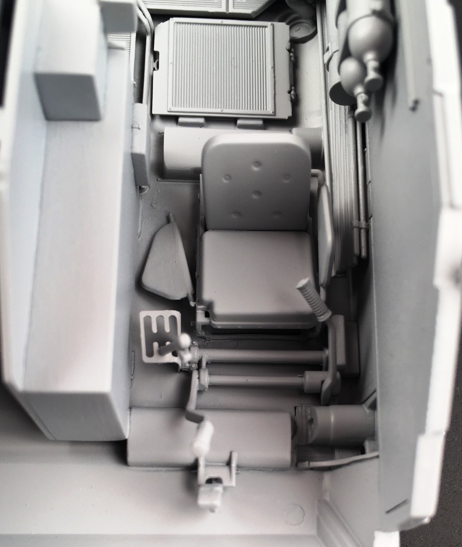
Drivers position
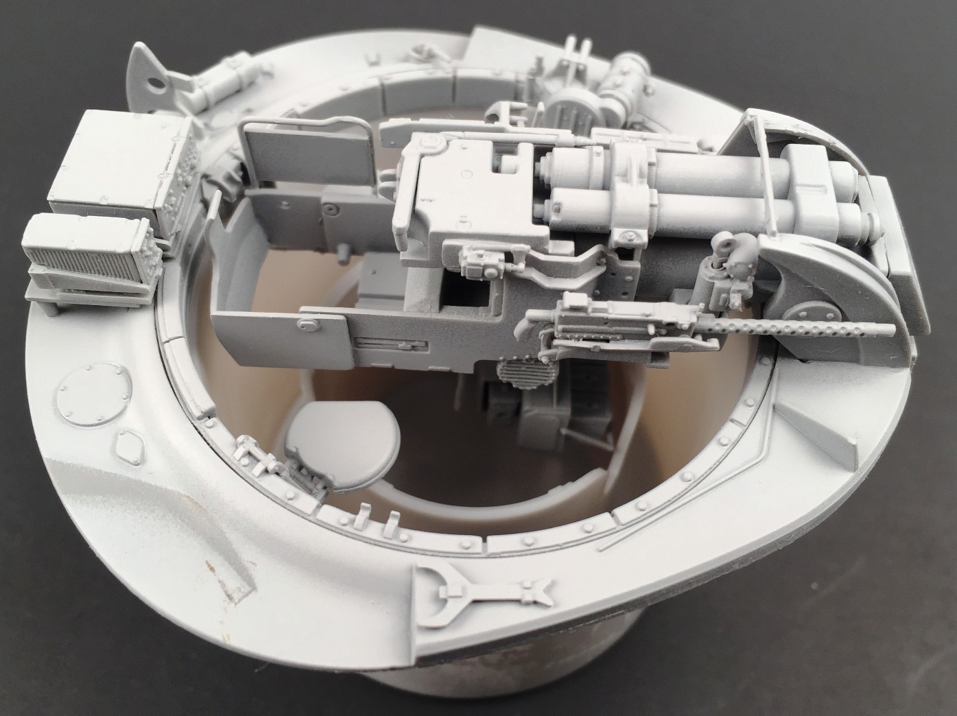
Turret interior
Turret interior
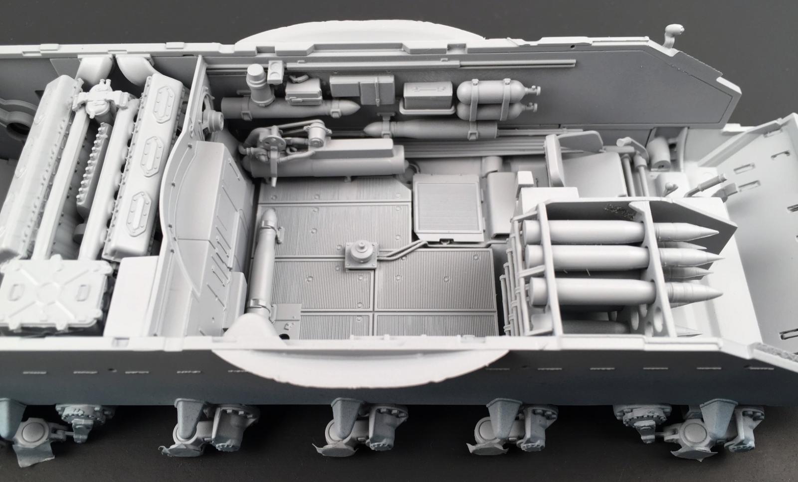
Interior of tank
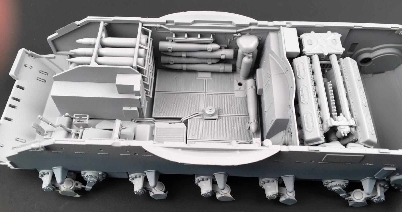
Interior of tank

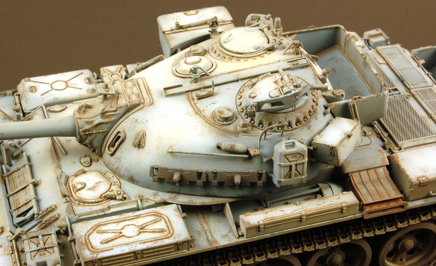
Finished model of Tiran 4 late
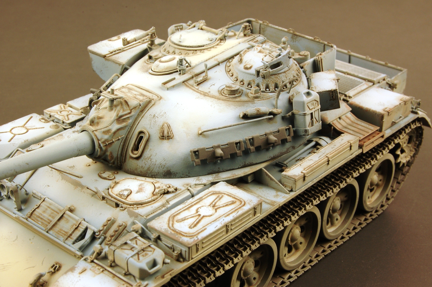
Finished model of Tiran 4 late

Finished model of Tiran 4 late

Finished model of Tiran 4 late
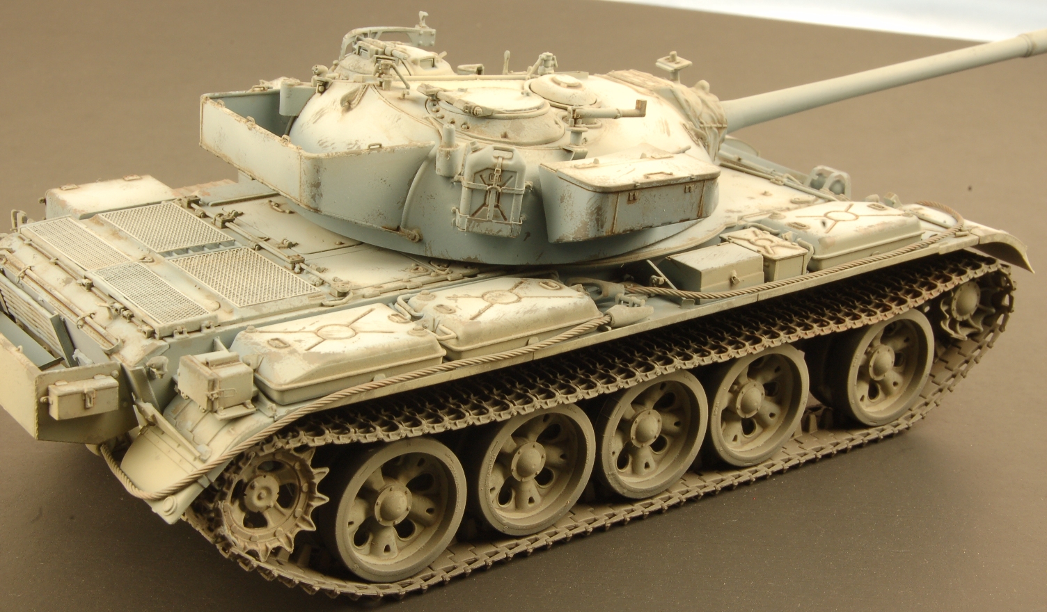
Finished model of Tiran 4 late
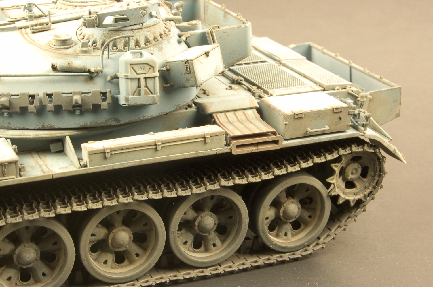
Finished model of Tiran 4 late
Comments
Add new comment
This site is protected by reCAPTCHA and the Google Privacy Policy and Terms of Service apply.
Similar Reviews