
T-54-3 Soviet Medium Tank Mod 1951 Interior Kit
Brief History
The T-54 and T-55 tanks are a series of Soviet main battle tanks introduced in the years following the Second World War. The first T-54 prototype was completed at Nizhny Tagil by the end of 1945. Initial production ramp up settled for 1947 at Nizhny Tagil, and 1948 for Kharkov were halted and curtailed as many problems were uncovered; the T-34-85 still accounted for 88 percent of production through the 50's. The T-54 eventually became the main tank for armoured units of the Soviet Army, armies of the Warsaw Pact countries, and many others. T-54s and T-55s have been involved in many of the world's armed conflicts since the later part of the 20th century.
The T-54/55 series eventually became the most-produced tank in military history. Estimated production numbers for the series range from 86,000 to 100,000. They were replaced by the T-62, T-64, T-72, -80, T-90 and soon, T-14 tanks in the Soviet and Russian armies, but remain in use by up to 50 other armies worldwide, some having received sophisticated retrofitting.
During the Cold War, Soviet tanks never directly faced their NATO adversaries in combat in Europe. However, the T-54/55's first appearance in the West around the period of the 1950s (then the beginning of the Cold War) spurred the United Kingdom to develop a new tank gun, the Royal Ordinance L7, and the United States to develop the M60 Patton tank.
Personal Comments
This is my second build of a MiniArt injection-molded military vehicle kit. I also built and painted one of the MiniArt building models, which was a vacuform kit with some injected plastic details and accessories. I especially appreciate the tutorials offered by MiniArt on their website for the assembly and painting process for their building kits. This material was extremely helpful. The MiniArt website is a worthwhile visit for the scale modeler. I did reach out to MiniArt at the start of the build to bequest their permission to use some of the images from their website, and they were most gracious in their approval of this request.
I had seen the various T54 series tank models in-the-box reviews on several websites and the comments were generally favorable. I liked the looks of the vehicle and was intrigued by the complete interior and the challenge it offered. When the opportunity arose to review this kit I volunteered.
The Kit
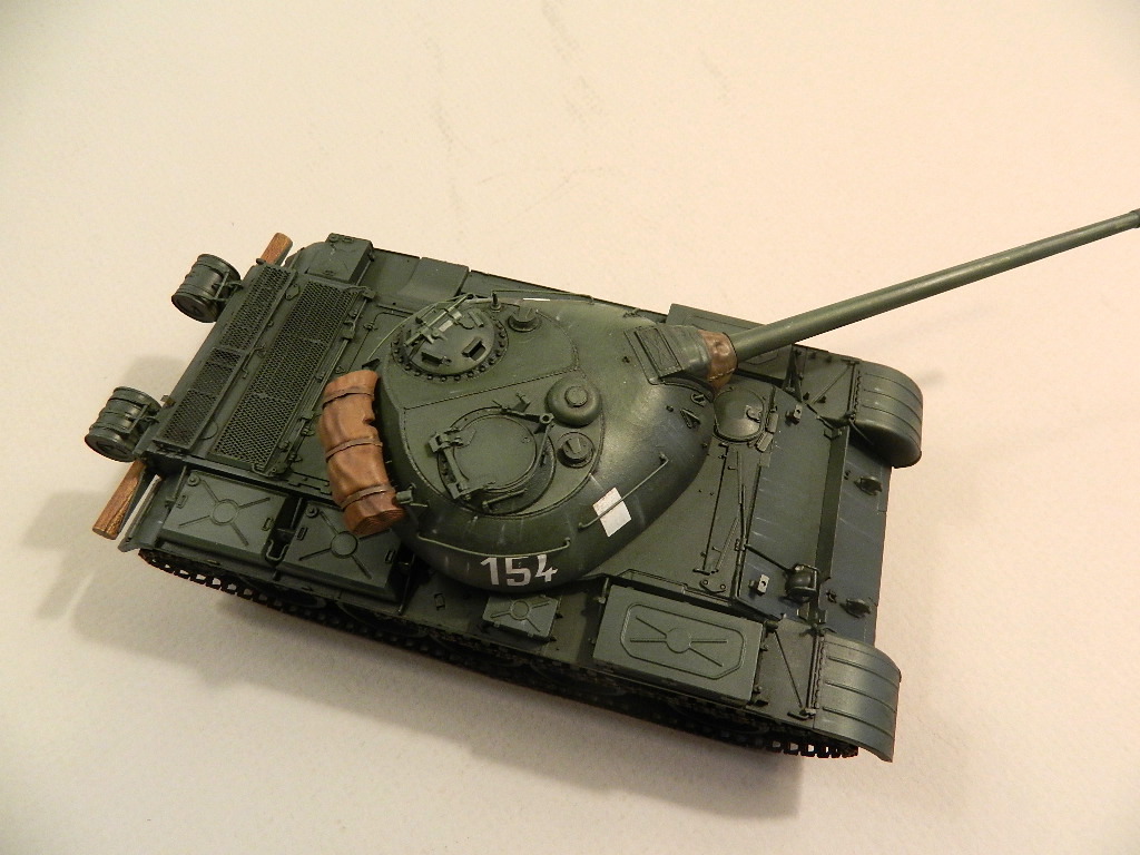
The box contains 1045 parts, of which 911 are medium grey plastic, 118 are photoetch, and 16 clear parts. Each sprue has an identifying tab. Ejector pins marks will be addressed if and when they are an issue. Everything is packaged in a single clear plastic wrap, plus individual packaging for some of the other sprues. The PE frets are enclosed in a card stock envelope. Markings for 7 vehicles are included on the decal sheet. Once the packaging is opened and the sprue removed I began to see how involved this build would be. There is a lot of plastic in the box. The molding of the parts appears to be crisp and finely detailed. The sprue-to-parts attachments will require care when removing the smaller parts.
Parts not to be used in the build are noted on the sprue layout sheets. I did not remove these parts until the construction was completed to avoid any possibilty of inadvertantly removing the wrong parts.
The interior (fighting compartment, driver's station and the turret) are fully detailed. Torsion bars are noted as workable, hatches may be posed open, and a detailed V-54 engine is included. There are 73 sprues for the plastic parts, two clear parts sprues and two PE frets.
The Instructions
The instructions are in a 24 page manual form, full color and include 89 construction steps to complete the model. Each step is represented as an exploded view, with parts numbered and paint colors noted. A color chart is also provided with five paint manufacturers identified. There are several color profiles of the vehicles included for reference.
The instructions should be thoroughly reviewed at each construction step, and reviewed again, along with a peek or two ahead to avoid possible conflicts. The test fitting of parts and subassemblies will be the order of the day due to the complex nature of this kit. I did find that test-fitting was not always possible due to the many small parts and complex nature of a particular subassembly.
Construction
Engine. There are eight steps to the engine construction. I reviewed the steps of construction several times before removing any parts from the sprues and decided to paint the various parts and sub-assemblies before bringing all the engine parts together. There are several sprues involved in the engine assembly. There are a lot of parts that make up the engine and planning is required to make certain everything fits properly. The plastic seemed a bit soft and a sharp hobby knife is required to remove spurs and mold lines. The parts fit together fairly well, but some care is required to close gaps between several of the parts. There are many very small parts included in this assembly and care must be exercised to avoid losing any on them.
The semi-complete engine will not be installed in the lower hull until step 22 on page 11, and even then additional engine parts will need to be installed in that step.
Lower hull. Steps 9 through 25 are dedicated to the assembly of the lower hull. The complex nature of the model reveals itself once again here. Review the instructions and test fit the parts before committing the solvent when possible.
Parts from several different sprues are again involved in the assembly of the lower hull (step 9). I searched through the mountain of sprues and found the ones I needed and set them in the work area. Parts S38, Tc9, S34 and S36 are hull mounts for the road wheels and appear to be misidentified for their locations (or it may have been my interpretation of what parts go where?). I dry-fitted all because collectively they will determine if the vehicle will set level on its road wheels. In addition I noted the assigned locations did not match the parts' shapes as shown on the instructions. The fit of these parts to the hull (part Ma6) is not positive, resulting in a slight bit of play in each mount before the solvent was applied. I should have been concerned about the fit of the lower hull components at this point in the build.
Step 10 is quite complicated as it addresses the torsion bars and swing arms installation. Various parts from twentynine sprues are involved. In addition this step offers the option to fix the torsion bars in place or allow them to be moveable. Although the cover page of the instructions note the torsion bars to be workable at this point I saw this as a potential problem. I assembled all five swing arms and torsion oars on one side and dry-fitted them in place. This is tricky to say the least. I found the torsion bars to be too long for the swing arm male part to fit into the hull socket. After trimming the torsion bars the swing arm fit into the hull locations. The front and rear swing arms have addition parts that form secondary swing arms: these should be moveable, but had the tendency to fall off. The isometrics are not clear as to the vertical orientation. I referred to the side views of the models in the painting and decal pages, and saw the center of the road wheels was aligned with the bottom of the hull. I aligned the swing arms to meet this criteria and glued them in place as I noted the torsion bars would not be workable. The opposite side was finished in the same manner.
When the time came to install the lower hull sides I found there were conflicts with several parts installed on the hull bottom panel as part of an earlier step. The construction of the pan is so complicated with so many parts there is no room for error. In retrospect had I heeded my initial concern I should have disregarded the instructions and built the bottom pan with the two sides and the front and rear panels as a first step before installing all the parts associated with the drive sprockets and road wheels. I found parts B44 and B45 that hold the extra main gun shells, and part S8 the fire wall all a bit too wide to allow the right side to fit properly. Some trimming was in order here. Had I built the hull bottom and side first the interior compartment bulkhead may have fit better. The right side of the hull would just not fit to the hull bottom without some trimming and adjustments.
Upper Hull. Faced with the major fit issue with the lower hull I decided to fit parts for the upper hull in place ahead of the instruction's steps. I made this decision is an effort to help reinforce the lower hull construction and form a stronger assembly.
I first fitted the turret base plate to the hull, less the small parts. The engine access plate and covers (parts Te6, Ma4 and Ma3) were glued together and that subassembly was set in place dry and abutting the turret base plate. I wanted to make certain everything fit as the rear portion of the upper hull appeared to be a busy assembly. Part Q10 is a delicate piece and required some effort to clean up the sprue attachments. Part C15 attaches to part Q10, and the diagram is somewhat misleading. Part C15 is a rectangular shape, but the instructions show it in an end view of the long side. Once I figured that out I found the end of C15 attached to the center of part Q10. This was a weak connection. The sequence of fitting the parts in place was not clear to me so dry-fitting of the parts allowed me to determine how the parts would go together before the solvent was applied.
Fenders. The fenders are an off-the-model subassembly of several smaller subassemblies of fuel tanks, tool boxes, reinforcing brackets all comprised of plastic and PE parts. Parts from several different sprues are again required to assemble each fender. I started with the right side. The rear fold up section of the fender has nothing to align with other than the rear edge of the fender top. I applied the solvent, set what looked like the correct angle and set it aside to harden.
The fenders attach to the sides of the hull, and are aligned with small nubs and corresponding shallow depressions in the vertical wall. This struck me as potentially weak joint, and I reinforced it with a 5" long strip of Evergreen number 291 angle on each side.
Upper hull. About the time I was ready to begin work on the upper hull I began to realize that I had done a lot of work to assemble the interior and this work will be concealed after the upper hull is completed and installed.
Roads wheels and sprockets. The road wheels and sprockets are shown to be assembled and installed in steps 26, 27 and 33. I assembled the various parts and set everything aside to be painted separately and installed once the hull had been painted.
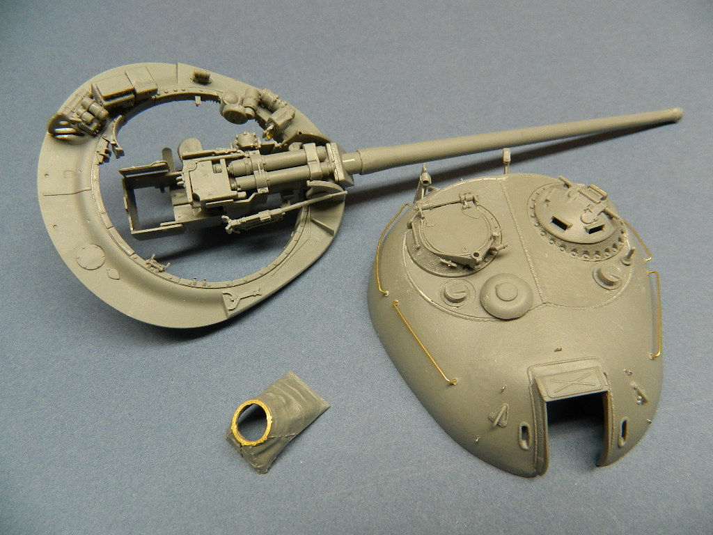
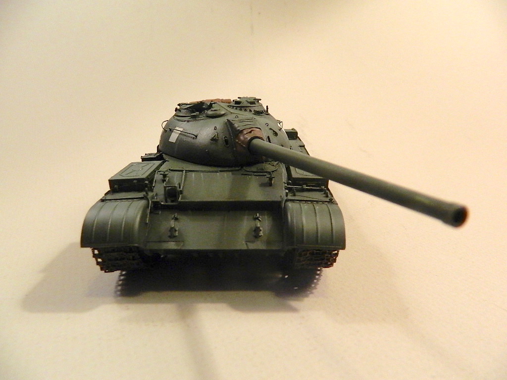
Turret. As complicated as the hull assembly is, the turret is equally daunting. There are 27 steps and about 260 plastic and PE parts required for the turret and main weapon construction. Several steps are dedicated to interior detailing. The first requires the fitting of two rings to form the turret ring. Part Ba7 fits inside of part Q11, and the former requires a great deal of care to remove from the sprue and removal of the many sprue connectors. Fitting this ring to the turret bottom is shown in step 55 and required a good bit of study to determine the configuration of the assembly, but it did go together.
There are several very tiny PE parts that attach to the front of the turret. Rather than attempt to place these microscopic parts I used very fine wire bent to shape and fitted into holes drilled where the surface has tiny location dimples. I also used brass rod to replace the long side turret grab rails.
Exterior Details
The DSHK Machine gun is made up with 21 plastic and 12 PE parts. The instruction views are at least 2 1/2 times larger than the actual parts. Looking ahead as to the gun mount on the turret there appeared to be amounting pintel on the bottom of the gun. The gun mount appears about half way through the subassembly build and once again in the front view of the assembled weapons. In reality the part was missing and I needed to improvise. The PE parts in several instances are microscopically small and removing them from the fret often distorts them. Aligning the plastic parts was extremely difficult, and cleanup of the sprue attachment points on the small parts was also quite challenging. Once the gun was assembled and the solvent cured, the parts were airbrushed with Tamiya XF-85 Rubber black. After the paint dried the surfaces were dry-brushed with graphite for the metallic look. This is a nice addition to the model, but is much too complicated. I did not mount the gun on the finished model as somehow some of the parts were knocked off and disappeared.
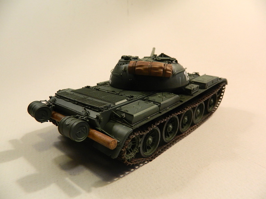
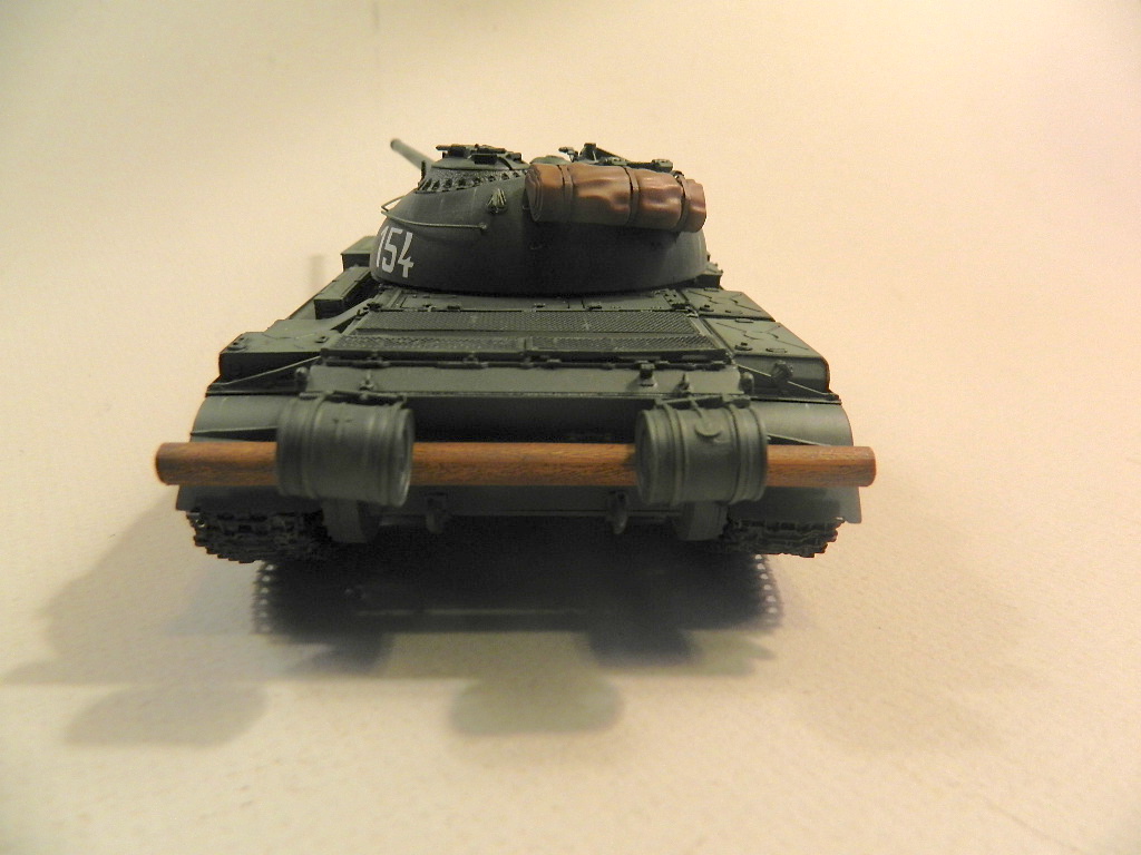
The kit includes a bridging log for mounting on the rear of the hull. After the sprue attachment points and mold seams were carefully removed, the log was painted Tamiya Flat Flesh, and a coat of burnt umber oil paint was applied. The oil paint was allowed to dry for about 15 minutes and the surplus rubbed off.
The tarp mounted on the rear side of the turret has three PE hold down straps that must be fixed in the molded in recesses. Thin super glue was used to hold the PE straps in place. The tarp and straps were airbrushed with Tamiya white primer, and when that was dry Tamiya Flat Earth was airbrushed onto the tarp. Once the Dark Earth had dried burnt umber oil paint was applied to all the recesses and allowed to partially dry. A wide brush dampened with thinner was then used to blend the oil paint, leaving the recesses dark. The straps were painted with Vallejo leather.
Tracks. I painted the model and running gear before I started on the track construction and installation. The tracks are made up with individual links, and there are 90 links per side. There are 19 links per sprue. Each track has four attachment points and each must be trimmed and the spur removed to allow a tight and square fit with the adjacent link. I started with the bottom run of links, and once fitted together I applied the solvent and allowed them to dry for 24 hours. Next I glued the road wheel and return roller in place on the suspension. I found that the road wheel on the right side, the center wheel, and the adjacent wheel to the front conflicted with each other. The center wheel needed to move back about 1/16" of an inch. Since the swing arms were all firmly fixed in place I needed a solution. I glued the road wheel to the painted tracks and centered it between the adjacent road wheels. This conflict I feel goes back to the initial construction of the hull lower pan and suspension system as shown on the instructions. The hull lower pan and sides should be assembled before the suspension system components are installed.
I test fitted the bottom run of tracks with the road wheels and found the track teeth were a bit too thick and would not fit completely between the road wheel halves. Add a coat of primer and paint to the tracks and the fit become more challenging. I carefully thinned the teeth that would fit in the road wheels. I assembled the remaining links and applied the solvent, allowing that to cure for about 20 minutes. I started by wrapping the semi-rigid length of tracks around the front return roller. The found the assembly to be much stiffer than I had expected. Some of the joins separated and it became quite difficult to keep the tracks in place. I realized at this point that I must assemble the tracks in smaller, more workable lengths. I would need to paint the tracks in place. Just what I did not want to do. I found a very short window of opportunity with these tracks to go from workable to stiff once the solvent has been applied.
Painting
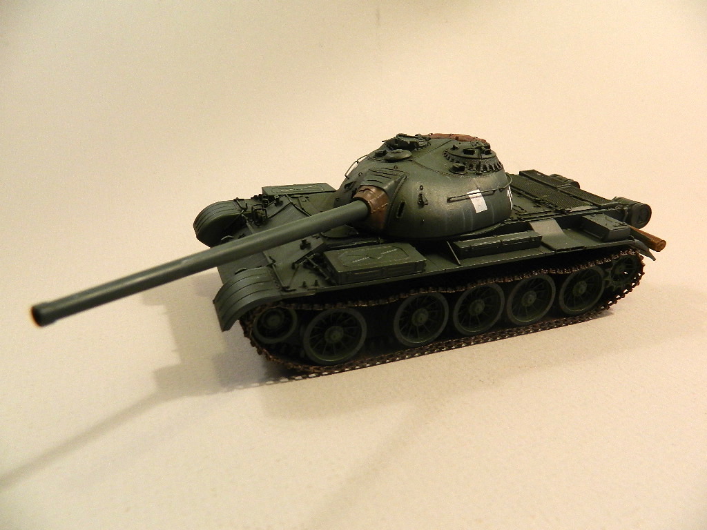
All the vehicles included are shown as Russian green, except one that has winter whitewash over green. I started the painting with an overall application of Tamiya NATO Black thinned with Mr. Color self-leveling lacquer thinner. I applied this color to all the nooks and crannies first to cover all the recesses and undersides of the various accessories. For the Russian Armor Green I used Model Master Acryl 4807.
Once the paint was thoroughly cured I applied several thin coats of Future in preparation for the decals.
Decals
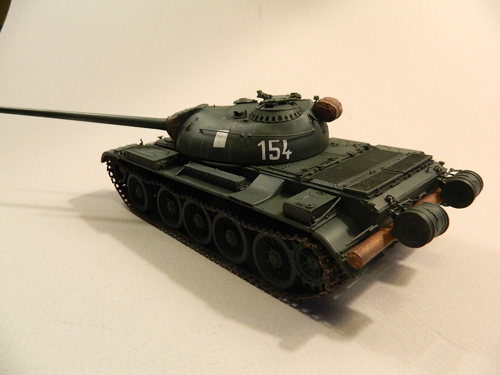
The hardest decision was to pick the markings for the model. I wanted contrast with the green finish so I picked white markings. My model required just four decals, and they offered no difficulty to apply and position on the model. The decals snuggled right down to the surface of the turret. Once the decals had been applied and allowed to dry, I airbrushed a thin coat of ModelMaster Flat Acryl to seal everything in place. Done!
Conclusion
I found this kit to be one of the most complicated builds that I have ever attempted. This most certainly is not a shake and bake kit by any means. It will require care, planning, patience and perseverance, and lot of dedicated time. The many small parts (plastic and PE), some are almost microscopic, will need extra care to remove from the sprue or PE fret, plus careful removal of the attachment stubs. All the small parts must be carefully put in place with needle nose tweezers held by a steady hand. I recommend that the builder thoroughly review each step of the instructions before cutting any parts free from the sprue. Look ahead to the next step for clarification of parts orientation. Sometimes the busy instructions are a bit vague as to how a particular part is placed, and on occasion parts numbers are mislabeled. In addition, make a list all the sprues required for each construction step and find and set them aside to avoid hunting through the vast pile of plastic later. It would have been helpful if the parts for a particular subassembly were on the same sprue rather than on several. There are many very small PE parts that are installed in a number of subassemblies. These are so small it was difficult to remove them from the fret without distorting them in the process, and I found that they added very little (no pun intended) to the model, so I sometimes left them off.
Contrary to what the instructions show I would recommend fitting the many smaller, and delicate exterior subassemblies in place after the hull and turret are basically assembled. I did find the need to hold several parts together with clamps while the solvent set up. It seemed like the soft nature of the plastic required a longer cure time for the joins to harden, the tracks being the exception.
Some modelers will be intimidated by the sheer volume of plastic parts, and the many steps to build this kit, and therefore this kit is not for the beginner. You will quickly learn to organize the various sprues to avoid searching for parts during the assembly phases, but search you will anyway. Hunting for the many parts became quite tedious. However, those modelers that enjoy a challenge this is the kit for you. This will be a time-consuming project as there are many small parts and several subassemblies that must be built and painted before various main assemblies can be brought together.
I do feel the kit is an ambitious effort by MiniArt and is overly complicated with all the parts and construction steps. The model has great detail and potential, but possible assembly errors by the modeler could cascade to major fit problems later. The hull tub assembly was particularly difficult. Once I managed to get the hull into a reasonable point of completion I finished the turret and decided to forgo any more effort at finishing or painting the interior components. I was more concerned with completing the exterior than finishing the interior that would be hidden from view. However, with careful planning and construction by the modeler the interior could be visible with certain components removed.
In several instances detail is provided by assembling many small parts, whereas molded on surface detail would probably more than suffice. The soft nature of the plastic is also somewhat detrimental to the build. Often I found the joins not to be structurally sound to support handling during later work. I had a few of the swing arms break off during some of the later steps. I did manage to lose a few parts and broke some of the more delicate ones. I used Tamiya thin cement for the project.
This kit has great potential in the hands of the right modelers. Overall the parts detail is amazing. For someone with the time, patience and skills, this kit offers a wonderful opportunity to paint and create a very nice, highly detailed model. With some skill and creativity the interior detail would be visible and stunning.
My thanks to Ben Mirson at MiniArt for his help, and to MiniArt and IPMS/USA for the opportunity to build and review this kit.


Comments
Add new comment
This site is protected by reCAPTCHA and the Google Privacy Policy and Terms of Service apply.
Similar Reviews