
T-54-1 Model 1947 Soviet Medium Tank
Background
The T-54/55 series of Soviet tanks are the most important tanks to see operation in the Cold War era, if for no other reason than sheer numbers: some estimates put total production at over 100,000 units. This series of tanks have also been used in almost every conflict of the second half of the 20th century, large and small, beginning with the invasion of Hungary by Soviet forces in 1956, the Arab-Israeli wars of 1967, 1973, 1982, the Vietnam war from 1967-75, the Iran-Iraq wars of 1980-88, the conflicts in Afghanistan, the Yugoslav Civil wars, and conflicts across Africa. This new, super detailed kit from MiniArt represents the initial production variant of the T-54 which started rolling off production lines in 1947, but suffered from a great many teething troubles. For a superb blog on the T-54, please check here: https://thesovietarmourblog.blogspot.com/2017/01/t-54.html
What’s in the MiniArt Box
- 74 sprues large and small of gray plastic parts (I kid you not!)
- 1 sprue of clear plastic parts
- 2 frets of photo etched brass parts
- 1 sheet of water slide decals with 4 different marking options
- 1 black and white instruction booklet, 24 pages, with 89 assembly steps and incorporating a color markings and painting guide
Before You Start Construction
Before you start construction of this kit, you will need to figure out a very important matter: how to create a sane system to keep track of where each sprue is on your workbench and the parts thereon. With 74 sprues, it is quite a task! I came up with the idea of getting a large document storage box, and a bunch of large file folders. These were then labelled “A”, “Ba”, “Cb”, “Hk” etc and the appropriate sprue(s) slipped into each folder. Then as you need a part, you reach into the storage box and pull out the appropriate folder and the sprue(s) contained therein.
Under Construction
This kit by MiniArt is a tour de force of model engineering, consisting as it does of 950 plastic parts, together with 105 PE brass parts. State of the art slide molding technology is used throughout the production of the plastic parts, and the model has a near complete interior: engine and engine bay, working torsion bar suspension, driver’s compartment and hull shell storage, extensive turret interior details etc. Interestingly, despite so much detail being incorporated elsewhere in the hull and turret, the transmission/radiator area is bare at the rear of the hull interior?
The plastic parts are festooned with crisp detail, and thanks one supposes to the use of CAD techniques in the design of the kit, the parts fit is extremely good. There were no sink marks anywhere on the parts in the review kit. However, here and there a little flash was present, though nothing that detracted significantly from the build experience. I noted no ejection pin marks on any parts visible once construction was concluded. One note however before construction begins: make sure you have a VERY fine razor saw blade.
Why? Because if there is one “fault” to this kit, in terms of ease of assembly, it is that some very fine parts are attached to the sprues by masses of sprue attachment points. Even though the plastic used by MiniArt in this kit is fairly robust and flexible, there is a risk of damage if you try to remove these finer parts from the sprues with regular sprue cutters. Be warned!
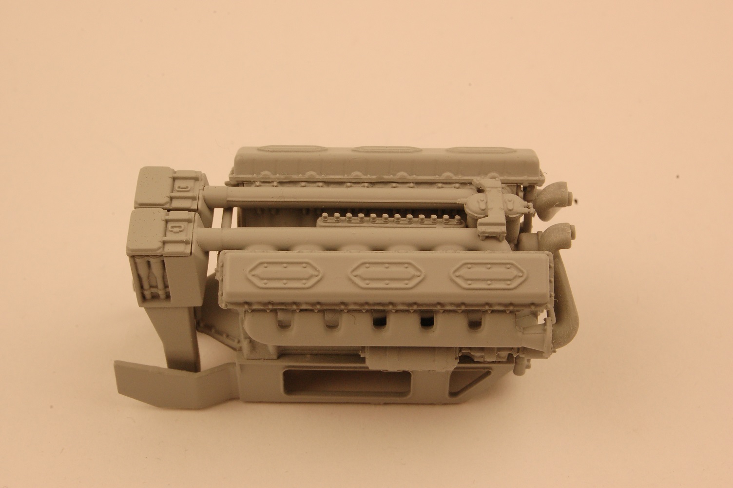
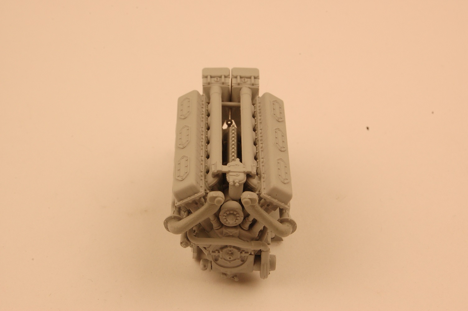
Construction of the kit starts with the very detailed miniature V-12 diesel engine. This subassembly consists of no fewer than 40 parts, a little kit in its own right! About all that is missing is the wiring harness, which if desired can be created utilizing some very fine wire. The fit of parts for the engine components is superb, and at no time during construction did I have pause to change my mind on this initial observation.
Following the engine comes the lower hull torsion bar suspension assembly sequences, assembly sequences 9 through 16, and continuing in sections 16 through 20. Read the instructions carefully here, as there are a number of parts, such as HO1, HO3 and HO4 where glue should not be used nor be allowed to accidentally come into contact with the parts, otherwise you will have issues with later assembly sequences. Also, be very careful in section 13, as there are a number of parts that look the same, but in fact are ever so slightly different. Mix them up and you will be in a world of hurt.
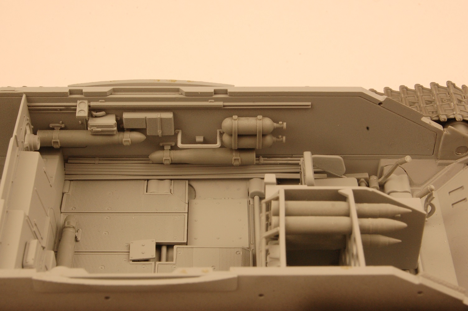
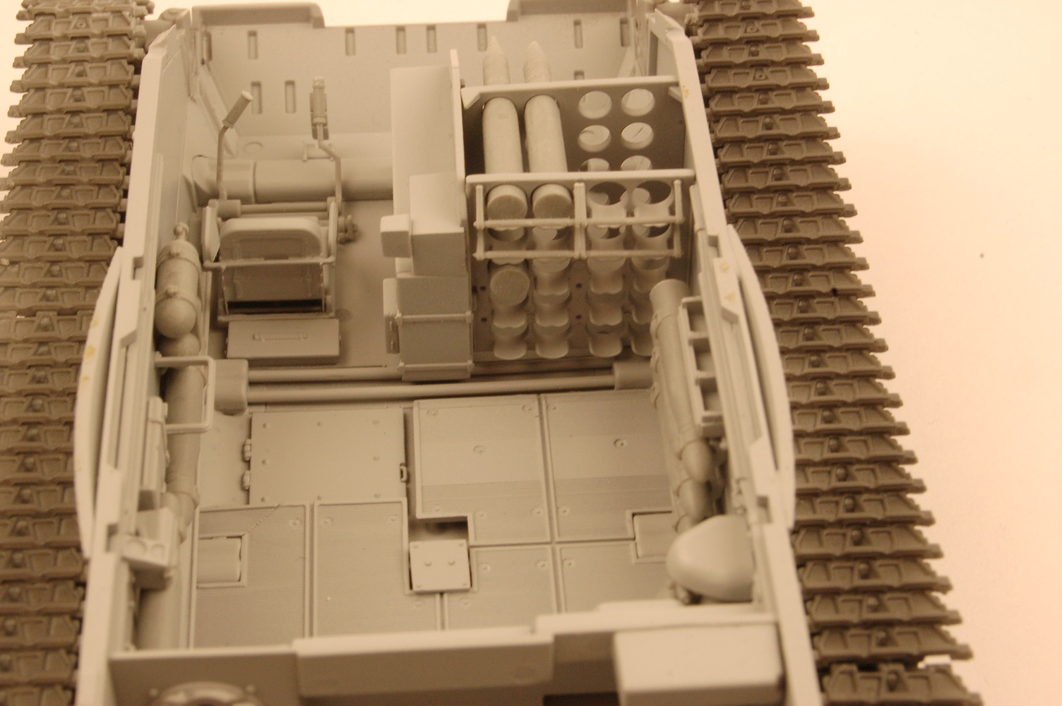
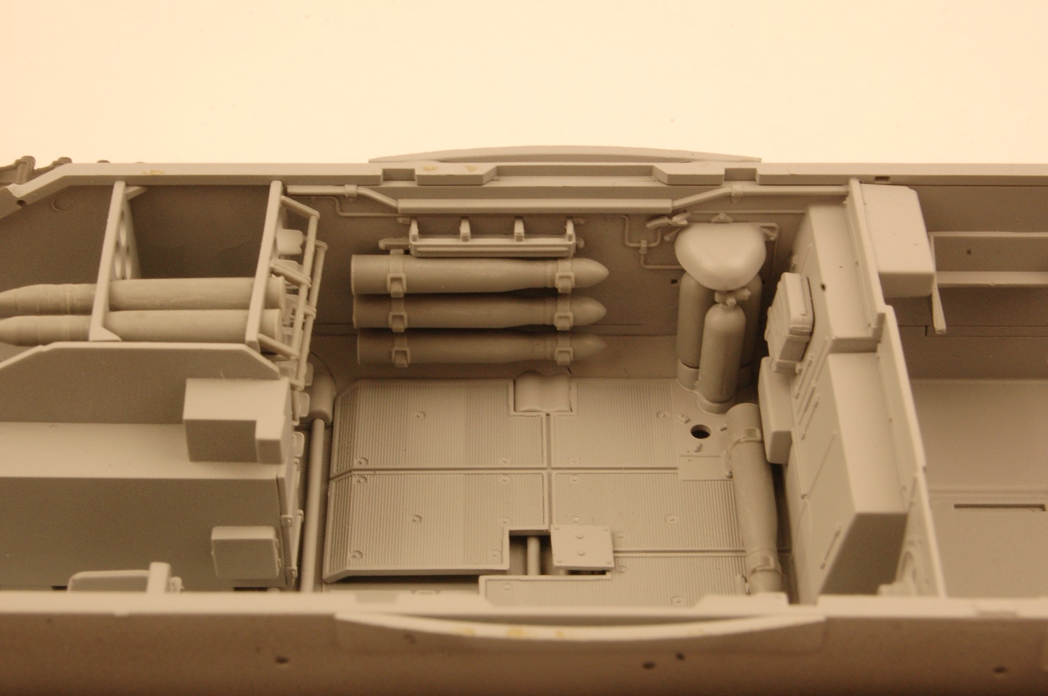
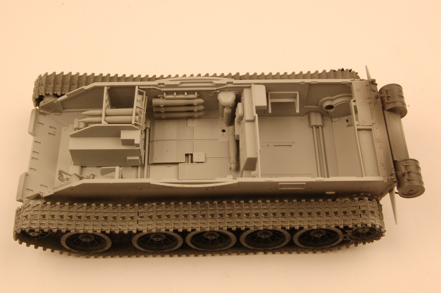
Assembly sequences 16 through 30 cover the assembly of the hull interior. There is a detailed driver area, including multi part seat, gear leavers and foot pedals etc. The interior sidewalls of the model are festooned with various boxes, compressed gas bottles and various controls, together with shells for the main gun. There is also a large shell storage rack and the 20 shells that go with it mounted on the hull floor. If you plan on displaying the hull “opened up” to take full visual advantage of all this detail, you will of course have to paint all these parts, and I would advise the modeler to do this in a series of subassemblies which can then be glued in place fully painted. Despite the crowded confines with all these parts, everything fits together remarkably well.
When it comes to the assembly of the ten pairs of main road wheels, MiniArt utilizes a pin, part HK4, which is mounted in a channel in the center of the main wheel assemblies (parts HK5 and HK6). The tip of this pin is glued into a slot on the hull suspension units. The pin end, and the slot it mounts into are half circle shapes. It would have been a more secure mount, in my opinion, had MiniArt designed the pin (and its mounting hole) twice the size, i.e. a full circle rather than a half circle. When you see the parts, you will understand what I mean. Once the main wheels are glued in place, and presuming you have assembled the torsion bar assemblies without getting glue where you shouldn’t, you will need to set the wheels up in a simple jig such that everything sets up firmly in a correctly aligned fashion.
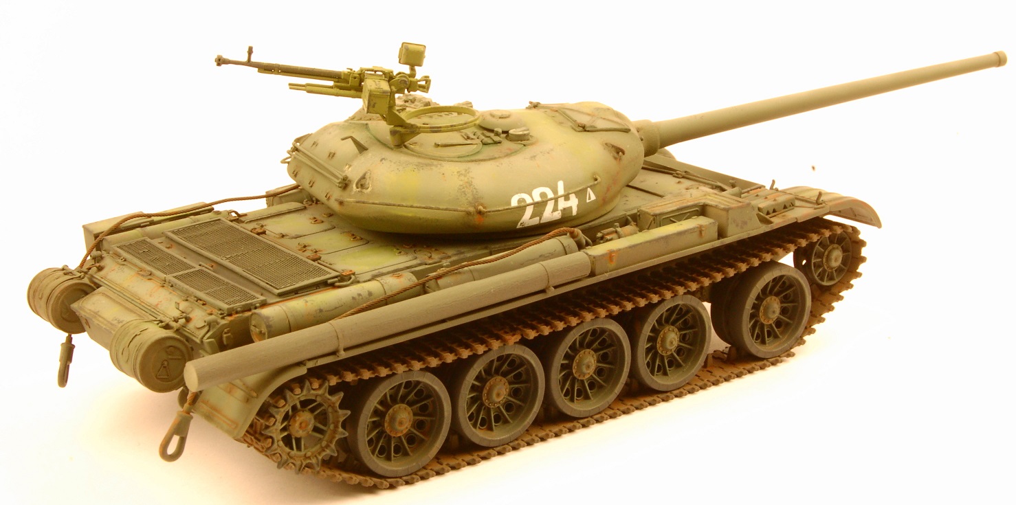
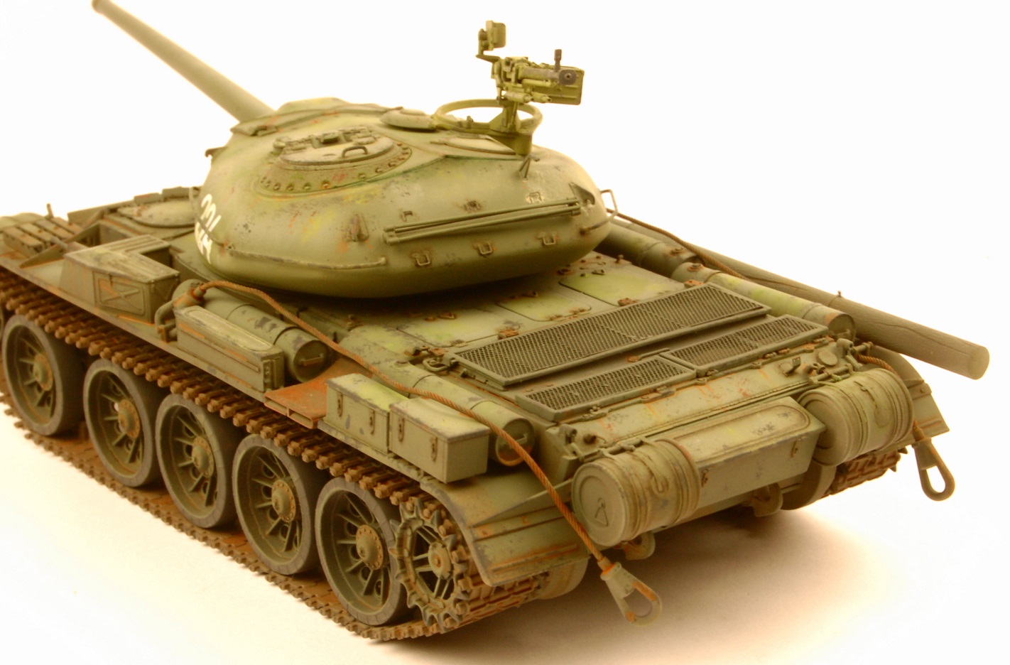
The next stages involve the assembly of the upper hull components, sections 33 through 44. Everything as mentioned earlier fits together nicely, and the instructions are well laid out so there shouldn’t be any difficult questions as to exactly where any particular part goes, or how things line up one part to another. HOWEVER, there are some parts which are particularly fiddly, and fraught with the danger of having them destroyed during their removal from the main sprues. In Section 33, part E4 is a lengthy, spindly part, and it has no fewer than ELEVEN sprue attachment points. You will need to carefully use the micro razor saw applying as little pressure in the sawing motion as possible to avoid breaking the part while removing it. Then you must carefully clean up the 11 attachment points utilizing a hobby knife and a sanding stick followed by sand paper. In Section 42, part E44 has TWENTY-THREE sprue attachment points! Same delicate process will need to be followed, first to remove the part from the sprue, and then to clean up the attachment points. The rear engine deck area has some lovely photo etched mesh screens for the air intake areas.
Section 45 has the modeler attaching the rear hull auxiliary oil/fuel tanks, which themselves were assembled back in Section 34 without incident. The attachment process involves lengths of photo etched brass, parts PEa35 x 2. These are mounting straps for the fuel tanks. At each end of these brass parts the modeler needs to form a loop, and the loops fit onto mounting brackets. In order to have the mounting straps taut so that the fuel tanks stay firmly in place, one needs to know how long the lengths need to be, including the loop part. No guidance is provided by MiniArt in their instructions. I would advise getting some printer paper, cutting lengths the size of the PE parts, and then guesstimating using the paper parts. Once you are satisfied with the length using the paper test parts, transfer the measurements over to the PE brass parts, and bend and fold accordingly.
Next in line for assembly are the vehicle’s fenders and the auxiliary fuel tanks attached to them, Section 46 through 49. As with the rear hull tanks, holding the fuel tanks to the fender supports are PE parts, this time two part. It will take planning, patience and perseverance to get these straps attached in good order, but the effort will be worth it. Also, attached to the fenders are machine gun “pods”, one on either fender facing forward, Section 51 - 53. On the real vehicle from a practical point of view these machineguns seem rather pointless, as they do not swivel side to side nor move up and down. In order to “aim” them in a general direction, the whole tank would need to be turned. They disappeared on the next iteration of the T-54, the T-54-2 Model 1949. Then Section 54 through 58 have additional fuel tanks and fender locker boxes installed.
Before attaching the fenders, the modeler needs to prepare and attach the link by link tracks. The molded detail on these tracks is outstanding, but a ton of grunt work is required to prep the links, as each link (180 links total) has either 4 or 5 sprue attachment points that need cleaning up. If you are a fan of baseball or American football and watch games on television, this is perfect for cleaning up such track parts, as there is lots of “dead time” between plays! Once you have completed all this work, however, you end up with great looking tracks installed on your model!
With the tracks installed, carefully glue the completed fender subassemblies to the hull sides. The fenders have pegs that slot into holes on the hull side walls, making for a solid structure. Glued on at this time is the engine exhaust outlet on the left rear side of the hull, parts Ba12/16/17. Once the fenders are firmly attached, it is time to sort out the one-piece tow cables, of which there are two. Here we have another example of the massive number of sprue attachment points for spindly parts: 10 per tow cable. The cabling is very well defined, and trying to remove 10 separate sprue attachment points was more work than I was willing to do, so I cut off the two shackles from the cable sections, drilled out the shackles, and utilized appropriately sized lengths of Eureka braided copper wire cables.
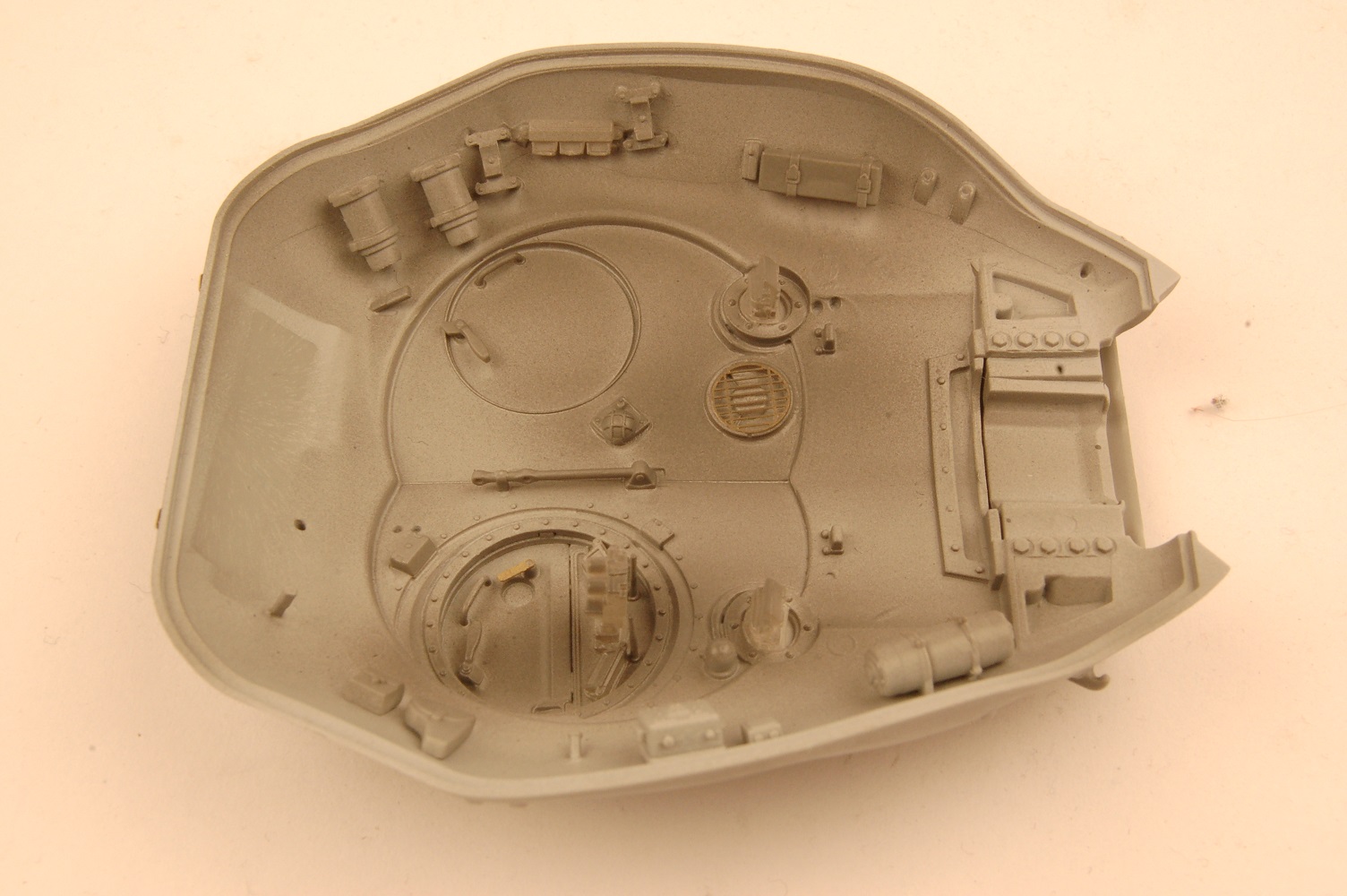
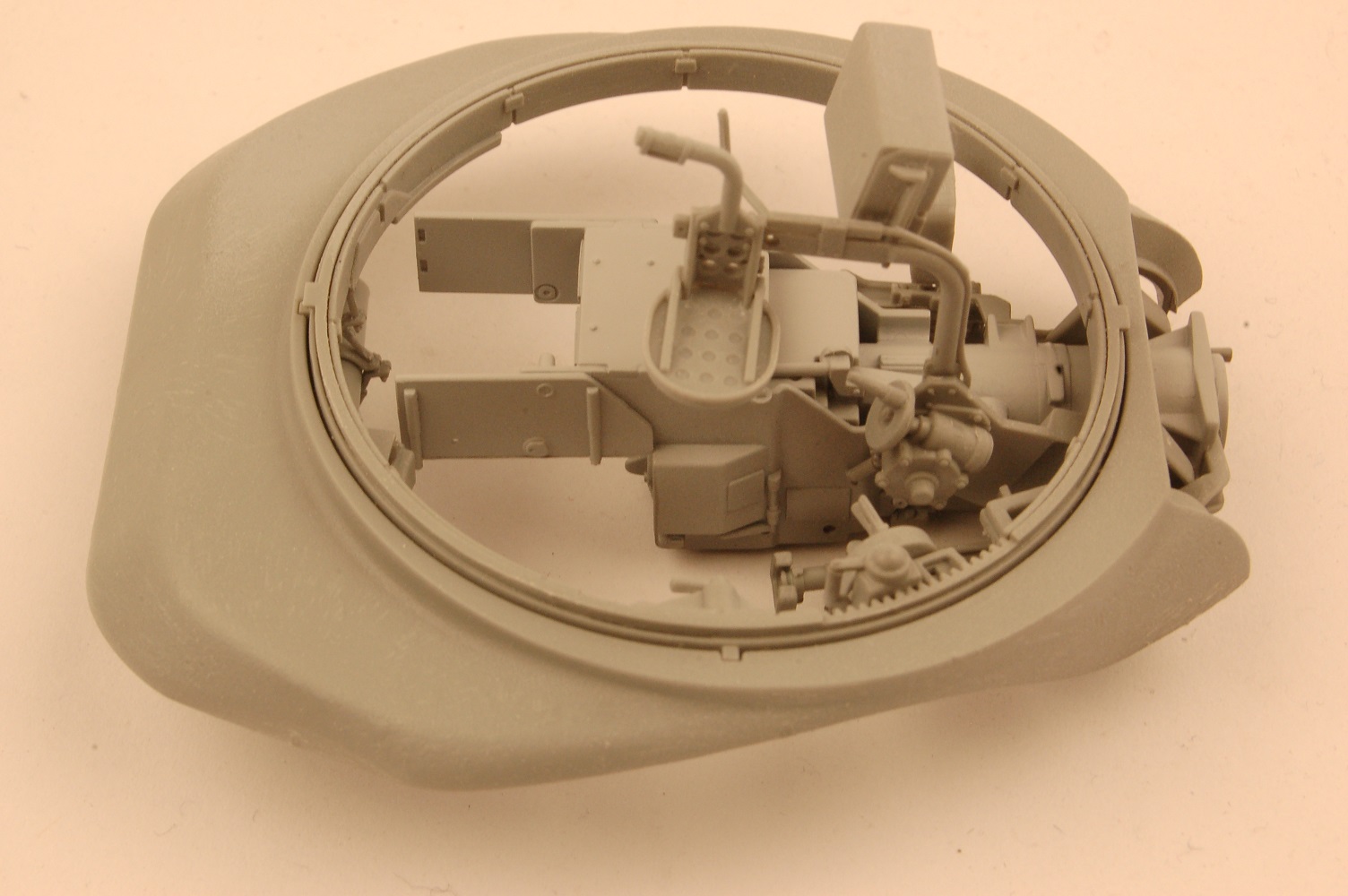
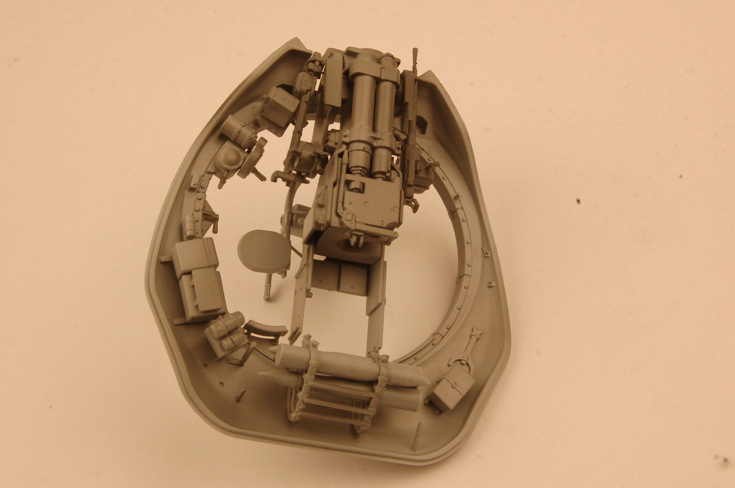
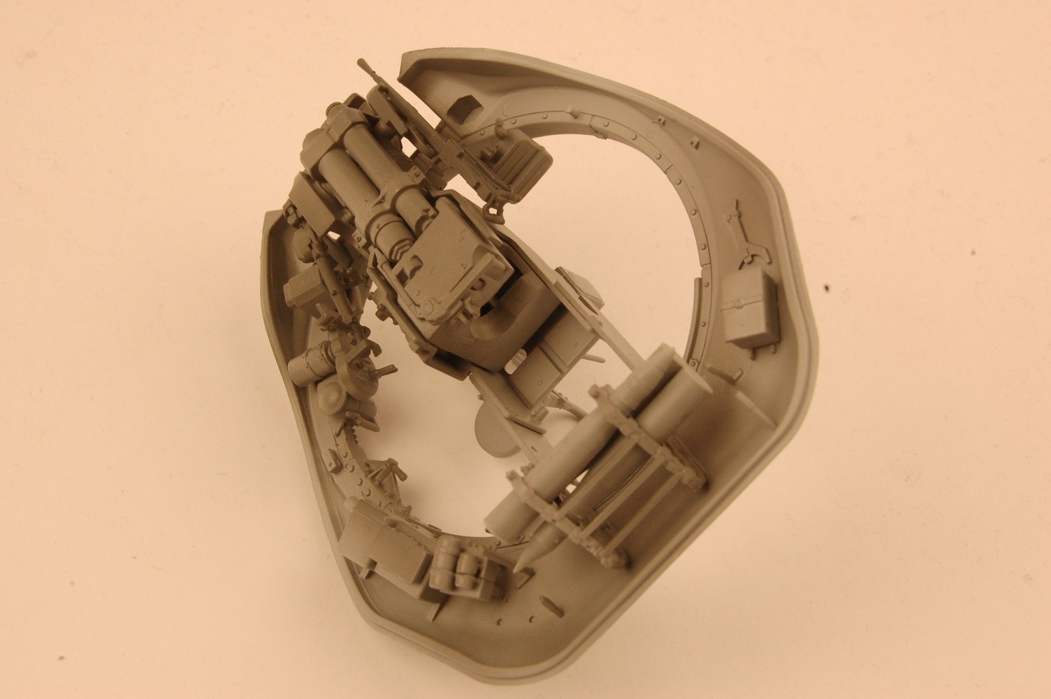
Now that the hull is completed, it is time to move on to the assembly of the turret interior, Section 62 through 72. As with the hull, the turret interior contains excellent detail, including but not limited to main gun shell storage racks and their shells, extensive main gun breach detail, gunner’s optics, turret crew seats etc. Missing is the cabling that links the various turret wall components together, but the online reference I mentioned at the beginning of this article has extensive photographic and technical manual detail of this cabling should the modeler wish to go to the effort of reproducing this. From an ease of painting point of view, much of this detail should be assembled into various small sub-assemblies, painted, and then carefully glued into place. All this detail makes for a very cramped interior, so be careful to position everything “just so” or you will find one component incorrectly bumping up and interfering with another.
Section 73 through 80 cover the two turret hatches and surrounding detail, along with some exterior turret detail. Some very small photo etched parts are involved here, so make sure you have a good set of tweezers to grip them with. If they fly off the tweezers, I guarantee the carpet monster will grab them and you will never get them back. And there are a few more of those difficult-to-remove-from-their-sprues spindly parts requiring careful cleanup post-removal: the turret grab rails. Both hatches can be positioned in either the opened or closed position, and both have excellent detail on the interior as well as exterior surfaces.
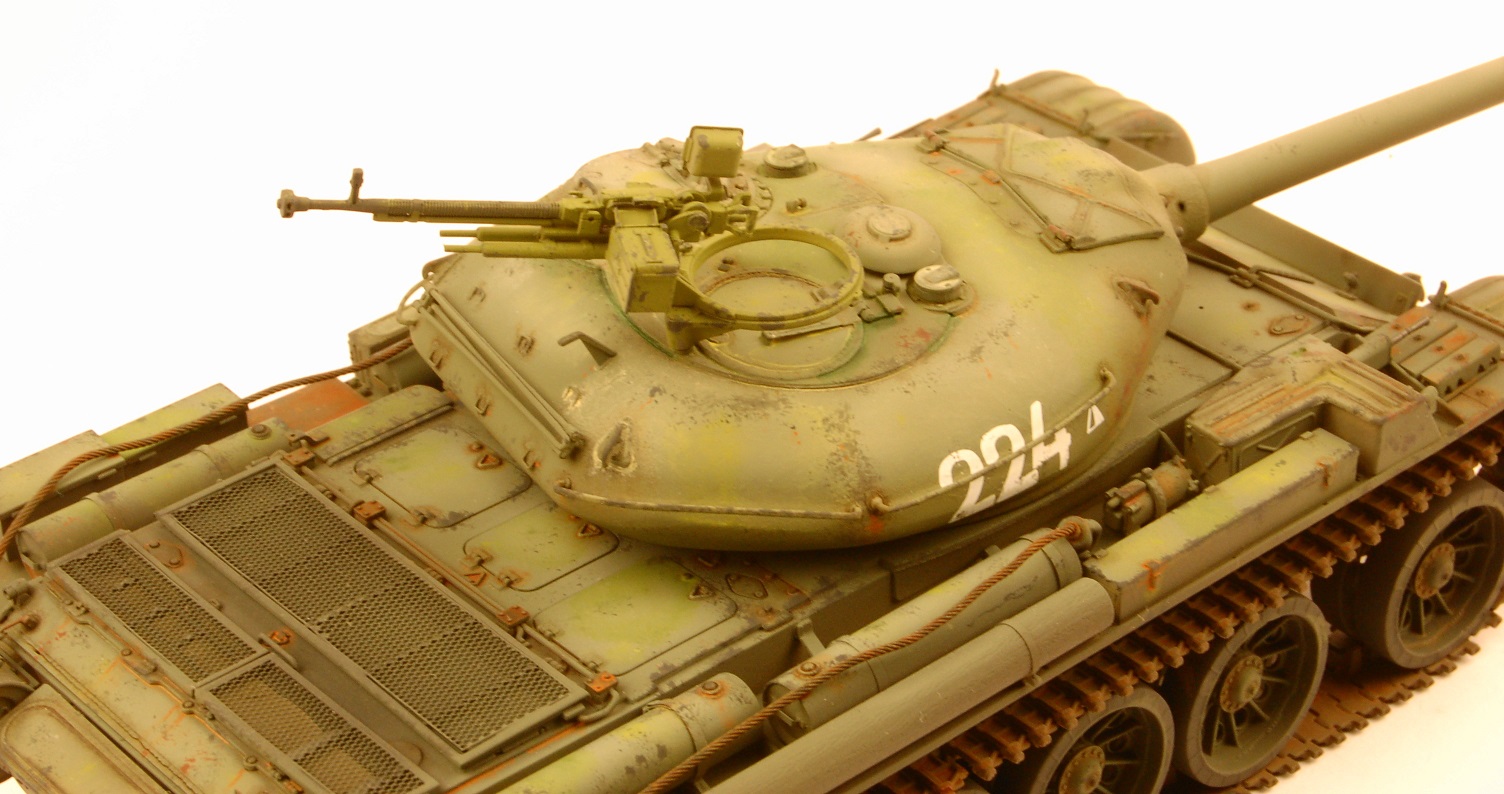
Into the assembly home stretch now, and MiniArt provides the modeler with a superb DShK machinegun for mounting on the turret roof. The gun is a little model on its own, consisting of nearly 30 parts both plastic and photo etched. Extreme care is required to get the most out of this little gem, but when completed it certainly looks sweet sitting atop the turret rear. Also to be assembled at this time is the coaxial machinegun for the turret interior, which again is well detailed at 8 parts. Next comes an optional all weather cover for the driver’s hatch, which includes a photo etched wiper blade! Then the upper half of the turret shell is carefully mounted onto the lower section, and you find out if all those interior parts you installed are in the right spot! The fit of the upper and lower turret sections was excellent, and all that was required once the glue was firmly set was to take a sanding stick and carefully remove the seam, checking reference photos if you can as being cast, there were casting imperfections in the exterior (that is, it wasn’t completely smooth). Finally comes the mounting of the one piece main gun (100mm D-10T), a lovely piece of injection molding, and its gun shield. Yes, the large main gun barrel has a seam that needs removing, but this was easily accomplished using a sanding stick and some sand paper after that.
Color and Markings
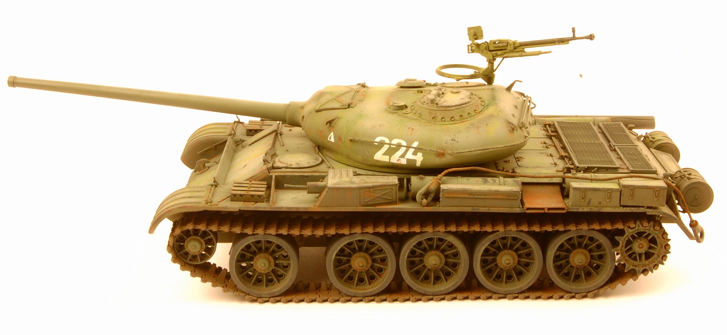
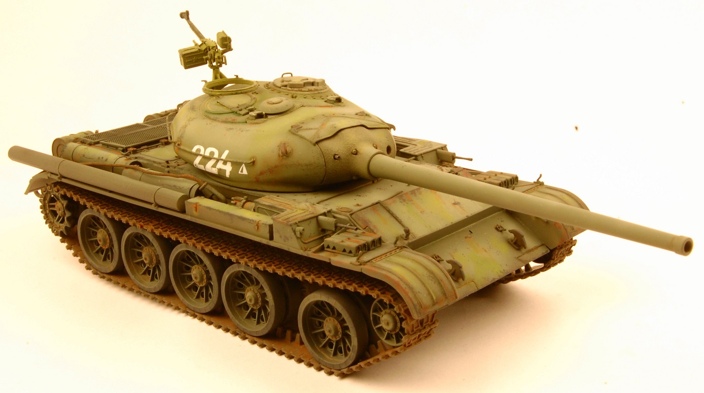
MiniArt provides a small decal sheet with markings for four vehicles. Markings Option 1 is listed as “Tank No. 6 initial batch, Factory No. 183, Nizhny Tagil, Summer 1947” with a simple “6” on the glacis plate and painted overall green. Option 2 is vehicle “224”, unit unknown, in overall green. Option 3 is vehicle “222”, unit unknown, again in overall green with a faded winter whitewash coating. Finally, Option 4 is a three-tone green, tan yellow and brown scheme listed as an “optional summer camouflage designed for use …. in the first half of the 1950’s”. It has no vehicle number, only two very small red stars on either side of the turret. Paint colors are called out in the instructions for the following brands: Ammo by Mig, Humbrol, Mr. Color, Testors and Vallejo. For my model, I chose vehicle “224” which was overall green.
For my green color, I decided to utilize a new range of acrylic paint produced by “Mission Models” of Salt Lake City, Utah which can be found here: https://modelpaintsol.com/model-painting/mission-models-paint
This paint doesn’t perform like other acrylic paints I have used, so for a tutorial on how to utilize it, please read this: https://modelpaintsol.com/guides/spraying-acrylic-paints-airbrushing-tips
I first primed the model using Tamiya rattle can “Fine Surface Primer Light Gray”. This is an acrylic lacquer product and one of the best primers on the market IMHO. I first get a bucket of hot water from the tap and immerse the rattle can in the water for 5 minutes. I remove and dry the can, and then shake the living daylights out of it, to insure a thoroughly mixed can of paint. The hot water heats the paint, thus allowing it to flow better, and by heating the can, I also increase the pressure within the can, thus providing a higher PSI as the paint exits the spray nozzle. This is particularly helpful when the can is less than a quarter full. The Tamiya primer leaves the model with a very smooth surface once fully cured, and doesn’t obscure the fine detail on the kit parts.
For the Russian Tank Green, I used Mission Models “MMP-031 Russian Dark Green 4BO FS34079”, thinning it per the advice in the article I listed above. I airbrushed the entire model with this color, and then created a post shading color using one part MMP-031 Green and one part “MMP-011 Dunkelgelb RAL 7028”. The Mission Models paint flows nicely out of my Iwata gravity feed airbrush at 15 psi, does not clog the tip, and cures to a tough finish. I then airbrushed a couple of light coats of Tamiya X-22 Clear Gloss thinned with their own band of acrylic thinner, over the entire kit prior to applying the decals. The kit decals are very thin, and adhered well to the smooth surfaces they were applied to, and being rather few in number caused no problems. Once dry, the decals were sealed in a couple of additional light coats of Tamiya X-22.
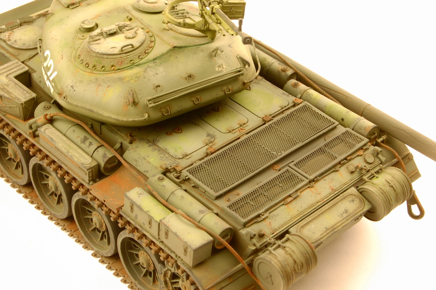
After the final clear coat was given a couple of days to cure, I mixed up some dark brown oil paint “wash”, and applied it liberally to the areas of raised detail and in the various recesses. This was allowed to dry for 24 hours before some Q-tips dipped in odorless mineral spirits were used to remove any excess “wash”. The model was then left alone for 72 hours to allow the oil paint wash to set up, before a few light coats of acrylic matt clear were applied. My favorite is AK Interactive’s “Ultra Matt Varnish AK 183”, the “matt-est” matt on the market. I airbrush this without thinning it, straight from the bottle.
I then hand brushed the rubber rims of the main road wheels with a suitable “Tire Black” from Vallejo, before painting the tracks by hand utilizing Vallejo 304 Track Primer. I then did a little “Expressionist” painting utilizing dots of oil paint: yellow, two different greens, white and buff. These were blended into the surface of the model using a wide brush and some odorless mineral thinner. The technique creates subtle tonal variations to the model’s surface. “Accurate”? I am not sure, but it does give the model a very nice visual appeal in my opinion. I also added paint chips utilizing a piece of sponge and some Vallejo gray and dark rust paint. I then finished off the initial weathering using two different hues of “rust” oil paint, thinned with odorless mineral spirits. In particular, the engine exhaust outlet was given a thorough treatment of “rust” as were the tow cables.
Finally, the anti-aircraft gun barrel on the turret was painted a suitably dark gray color, together with the two fender machine gun barrels and the turret coaxial machinegun barrel. One final coat of airbrushed over the entire model to seal everything nicely. A little highlighting was applied to the machine gun barrels with an artist’s graphite pencil to finish things off.
In conclusion, this is the most detailed injection plastic model I have ever had the pleasure to build. For your money, you get a ton of extremely well detailed parts for the turret interior and much of the hull interior. The exterior hull and turret detail is superb as well. The fit of these parts is excellent, and the instructions make it easy to figure out where each of the parts goes. I would recommend this model to more experienced armor modelers simply because of the massive number of parts, and the extensive use of photo etched parts during construction. Patience is the virtue needed with this kit, but if such is exercised, a superbly detailed model of a very important post WW2 Soviet tank will be the result to grace the modeler’s display case shelves. My sincere thanks to MiniArt of generously providing IPMS USA with this review kit.

Comments
Add new comment
This site is protected by reCAPTCHA and the Google Privacy Policy and Terms of Service apply.
Similar Reviews