
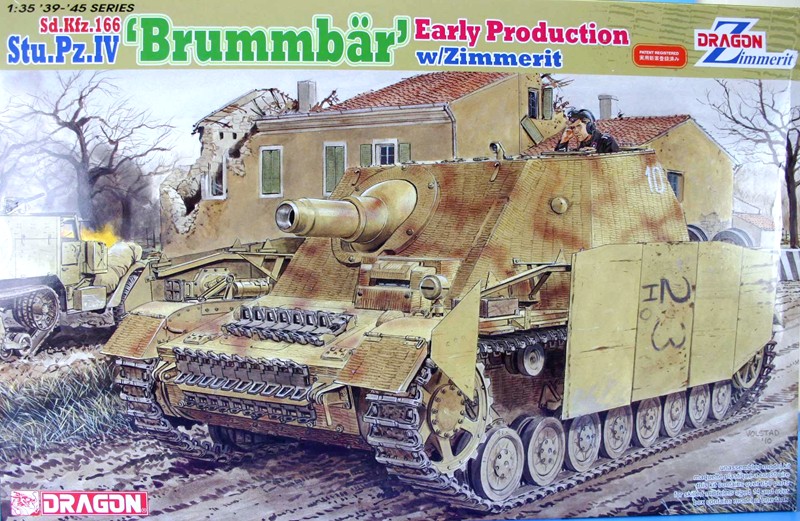
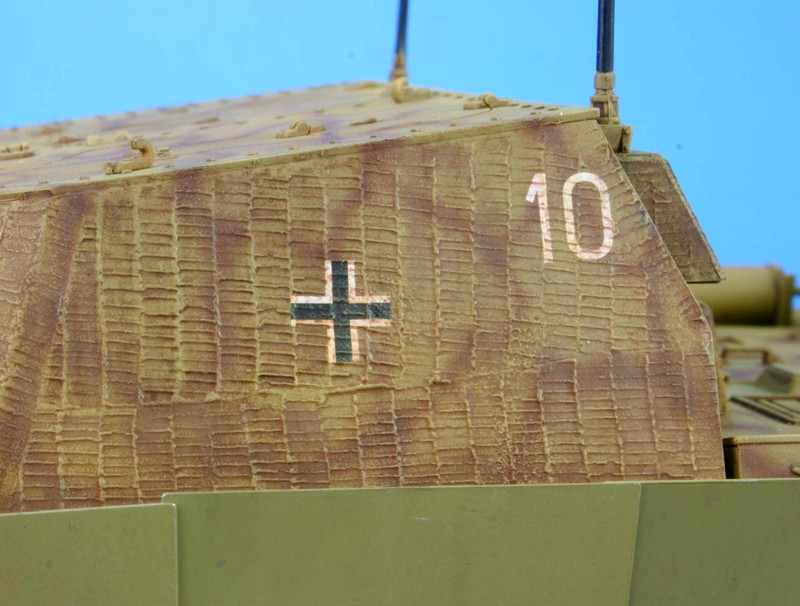
Stu.Pz. IV Brummbar Early Production with Zimmerit
Most Dragon models today are a collection of old sprues and new sprues added to create a new kit variant. In this case, Dragon has done so and in this case, redid the areas that had zimmerit applied. This being said, you have many options that need to be reviewed and decided on before you start this kit.
Steps 1, 2, & 3 - Lower Hull
As with most armor kits, the first step is the running gear. Remember those choices I mentioned in the paragraph above, well, here is the first one. You have a choice of two slightly different drive sprockets. The second choice is between the end caps over the bogie springs, and the third is the choice of mufflers.
The instructions give you two sets of muffler and you will need to drill out some locating holes depending on which muffler type you have chosen.
The bogies and wheels are pretty straight forward. The wheels have a mold seam down the middle of the tire. These are a pain to remove, but I made short work of it by using a Dremel Stylus drill with a high speed cutter that allowed me to shave off a miniscule thickness of the tire and then I finished up with a sanding stick to get a semi smooth surface. The bogies are designed to be articulated so careful assemble is required. The instructions show the road wheels mounted to the bogies at this time. I left the road wheels off for ease of painting, and then added them to the model late in the assembly process.
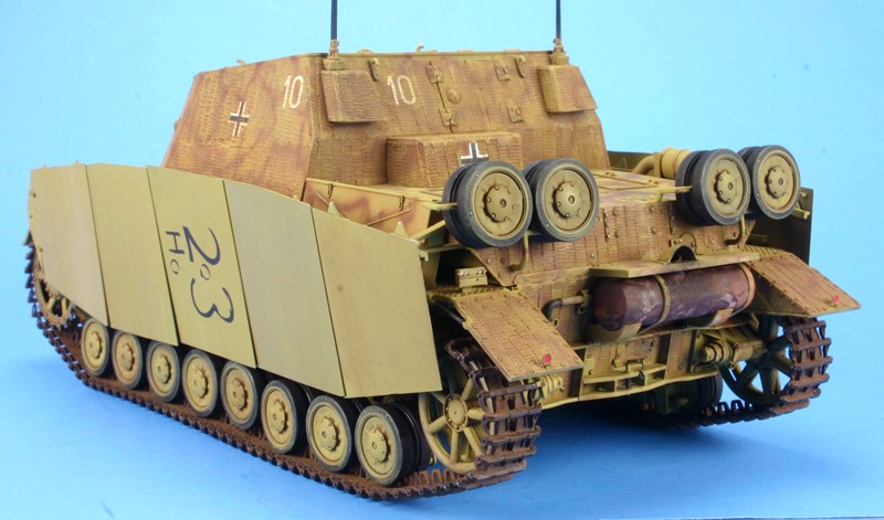
Step 4: Here the rear plate (with the muffler attached) is attached to the lower hull along with the additional glacis armor and transmission cover. The instructions show a choice of adding spare tracks to the transmission cover using either plastic or photo etched mounting brackets. However, this area is now covered with zimmerit patterns and no locating points are shown. The original marks for adding three tow cable mounts are depicted, but there are no parts for the mount or tow cable included in the kit. You will need to very carefully remove these three locating points from the zimmerit pattern. You will also need to determine how you will mount the spare track brackets without any help from the instructions. One choice is to leave them off entirely. A second choice is to attach the brackets directly to the spare tracks and add the entire subassembly to the model. This section also adds the bogie stops, drive sprocket covers and return rollers.
Step 5: This step added the bogies, idler wheel and drive sprocket. I glued the bogies in place (less the road wheels), but left the idler wheel and drive sprocket off for ease of painting and mounting the tracks at the end of the build.
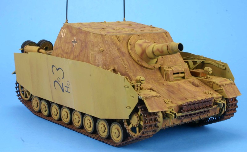
Step 6: This section covers the preparation of the fenders. You will need to determine if you are going to add the Schurzen plates or not. I chose to add the plates and this requires that you build a mounting bracket of 13 parts. The first thing to do is to remove the original mounting brackets. The instructions don’t tell you to do this, but the picture implies that this must be done. You can mount the parts G2 and G3 (small first plate brackets) now, but you should wait to add parts R1 and R2 until you have actually added the Schurzen plates to the model as the three bolts will not match the pattern on parts G2 and G3. You will need to make some adjustments so they all line up correctly. To make sure that this bracket is straight, I used a straight edge and laid down each part one by one. This kept the individual parts aligned until the glue had set 24 hours later.
Step 7 & 8: This step builds the jack and adds certain items to the fenders. I did not add these items at this time as I would eventually break them off. I did mount the fenders to the lower hull at this time.
Step 9: This step adds handles and other items to the inside of the hatch covers. As I built the model in the buttoned up mode, I skipped this step.
Step 10: This step adds the interior parts to the rear deck. These can be seen through openings so don’t skip these items. You will also have a choice of the rear back end, depending on which muffler option you chose back in step 3. Be careful when removing part E17 (muffler cover) from the sprue. The three mounting brackets look like sprue attachment points. Don’t cut them off as I did. Doing this makes it hard to mount the muffler cover.
Step 11: This step requires you to make a choice of the roof hatches depicted either open or closed. The open choice includes mounting a MG 32 machine gun and scissors periscope. I built the model in the closed position.
Step 12: This step has multiple options for the finishing the rear deck. The first option is for two or four spare road wheel brackets. The second option is for plastic or photoetch brackets. And the third option is between a fancy air filter and a plain adjustment tool. I chose the four road wheel bracket, PE brackets, and the fancy air filter.
Step 13: This step begins the buildup of the upper casemate. The only choice here is between plastic or photo etched brackets. These brackets cannot be seen once the rear deck is in place. I used the PE parts and everything fit okay.
Step 14: This step finishes the upper casemate with the addition of the armored visors and the outer gun mounting ring. There is a choice of showing the pistol port plug open or closed. The open position adds a photo etched retrieval chain. If you want to show this I suggest that you replace the PE chain with a real one.
Step 15 & 16: In this step you build the gun. The only optional choice is between two different aiming sights. If you build the model in the buttoned up mode, very little of the gun would be visible. I built it anyway because I know it is there.
Step 17: This step builds the gun cradle and mounting brackets.
Step 18: This step attaches the roof to the upper casemate and you have the option of adding part G7 (additional visor armor) to the model or not.
Step 19: This step brings the major subassemblies together. There is a floor plate that goes between the gun mount and the rear deck mount. If the hatches are depicted open, this floor is what will be seen. Paint it accordingly. The gun and upper casemate need to be attached at the same time. This will give you a little wiggle room to make sure everything is in alignment.
Tracks: These are Magic Tracks that require no cleanup unless you want to remove the ejector pin marks on the inner face of each track. These appear to be the proud type that will clean up with a swipe of the sanding stick or a sharp blade. These are not workable tracks so you will need to glue them together.
The method I use to glue the tracks together is as follows:
- I use a track jig that is adjustable. I place it on the work surface and put a strip of yellow Tamiya tape down with the sticky side up. If you don’t have a jig, you can use a ruler. Just tape it down and use it as a guide to keep the tracks straight.
- Then I “assemble” the track using the jig and tape to hold all the parts in place.
- I prepared the tracks one side at a time by adding a dab of Tamiya thin glue at each joint and letting this set for about 3 to 5 minutes. This will allow the glue to set enough to hold the tracks together but still be flexible enough to put sag into the tracks.
- Here I used a new tool from Hobby Trax, Part number HT 007. This is a track form that allows you to drape the glued, but not yet set, track around it. I taped the tracks down to the form to ensure the sag will be formed into the track.
- Let them dry.
- Remove the tracks. Paint and weather them off the vehicle.
- Mount the tracks to the model, along with the drive sprocket and idler wheels.
- When you are happy with how the tracks look on the model, glue the drive sprocket and idler wheel into their permanent position. Make sure that the tracks are correctly aligned. As one of the biggest mistake armor modelers make is to have tracks that are toed in or out caused by the improper alignment of drive sprockets and/or idler wheels.
Step 19A: Here I added all the small parts left off in prior steps.
Accuracy: The drawings found in the references listed below show the kit to be basically accurate. Since I’m not a rivet counter I don’t go beyond that. I model for fun.
Molding: I found the molding to be clean, with no sink marks and few ejector pin marks. The mold seams were easily removed and I saw no flash. Dragon makes extensive use of the pin nodes to keep ejector pin marks on the parts to a minimum. However, you will need to handle the removal and clean up of the parts with care.
Instructions: As with all Dragon’s instructions, read them carefully and plan what you want to do ahead of construction. Check the fit over and over and over again to make sure that all items fit together.
Painting and decals: The color call outs are for Testors Model Master enamel and Gunze paints. I continue to see a weakness in the painting instructions from all kit makers. Instructions for the small parts like the pioneer tools and travel lights are never listed or shown. Here you have to guess or mimic what someone else has done. The decals are by Cartograf and are up to their usual high standards.
The layout of the part sprues is as follows:
- Sprue A x 2 - (Black) Road wheels, drive sprockets, and idlers
- Sprue A x 2 - (Blue) Bogies
- Sprue B - Drive sprocket mounts, under hull items
- Sprue C - Tool box
- Sprue D - (Black) Gun mounts
- Sprue D - (Blue) Rear plate and idler adjustment apparatus. Many of these parts are not used
- Sprue E - (Black) Fenders, roof, rear deck hatches
- Sprue E - (Blue) Schurzen brackets and muffler guard
- Sprue F - (Black) Odds and ends. Most parts will not be used
- Sprue F - (Blue) Schurzen brackets
- Sprue G - (Black) Rear plates, front deck and hatches
- Sprue G - (Blue)
- Sprue H - Muffler and air intake baffles, most parts are not used
- Sprue J - Jack
- Sprue K - Odds and ends
- Sprue L - Extra Road Wheels
- Sprue MA - Photo Etch parts
- Sprue MB - Side one of Schurzen
- Sprue MC - Side two of Schurzen
- Sprue N - Upper casemate and rear deck
- Sprue P - Periscopes
- Sprue R - Leading edge Schurzen
- Sprue S - (Black) Odds and Ends
- Sprue S - (Blue) Periscope
- Sprue WC - MG 32
- Sprue X - Hull
- Z - Metal Cable for the tow cable
- Y - (2) Magic Track; 2 callout numbers with 240 actual pieces with none marked as not used.
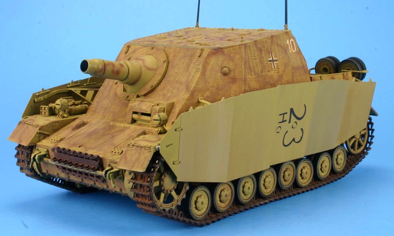
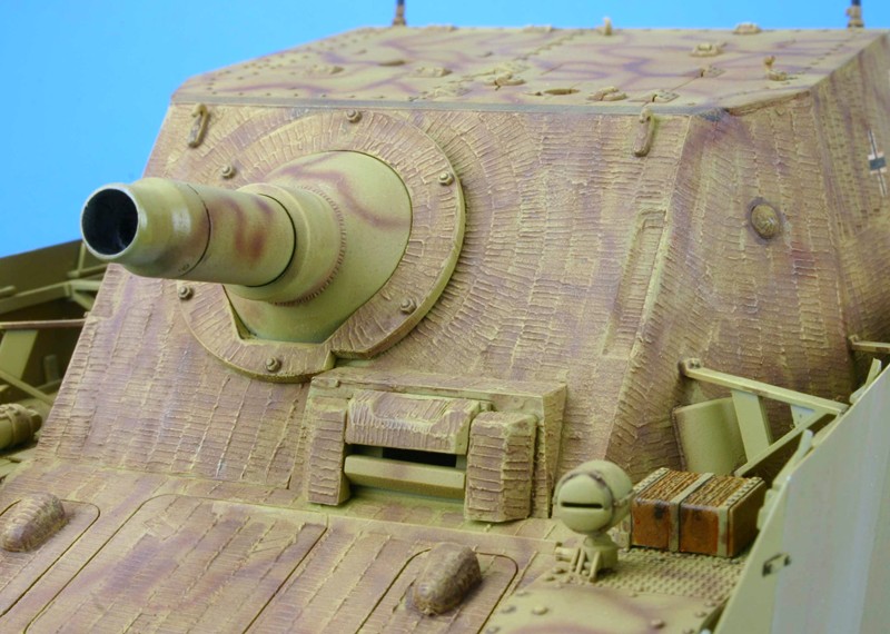
Conclusion: This builds into a nice model, the only real problem I have with this model is the zimmerit. It is very subtle. The zimmerit is not very pronounced, I tried a wash and dry brushing to make it stand out more, but I was not successful. My overall conclusion is that I had fun making this model, so I recommend it to you.
References for this variant are included in the following books:
- Encyclopedia of German Tanks of WW2, Revised Edition; Arms & Armour Press, by P. Chamberlain, H. Doyle & T. Jentz.
- Sturmgeschütz, s.PaK to Sturmmörser; Panzer Tracts No.8, by T. Jentz & H. Doyle.
- Sd.Kfz.166 Sturmpanzer Brummbär, Vol.1; J.J. Fedorowicz, by W. Trojca & M. Jaugitz.
- Panzer IV and its Variants; Spielberger Series Vol.4, Schiffer, by W. Spielberger.
- Panzers in Italy; Concord 7023, by T. Cockle & D. Jameson.
- German Sturmartillerie at War, Vol.1; Concord 7029, by F. De Sisto & L. Lecocq.
- German Sturmartillerie at War, Vol.2; Concord 7030, by F. De Sisto & L. Lecocq.
- Sturmartillerie and Panzerjäger; Osprey New Vanguard 34, by B. Perrett & M. Chappell.
Of course, there are others available.
Thanks to Dragon for the review sample and IPMS/USA for the review space.
This model can be found at most hobby shops, online hobby shops and at https://www.cyber-hobby.com.

Comments
Add new comment
This site is protected by reCAPTCHA and the Google Privacy Policy and Terms of Service apply.
Similar Reviews