
StuG.III Ausf.G, Part 2
Introduction
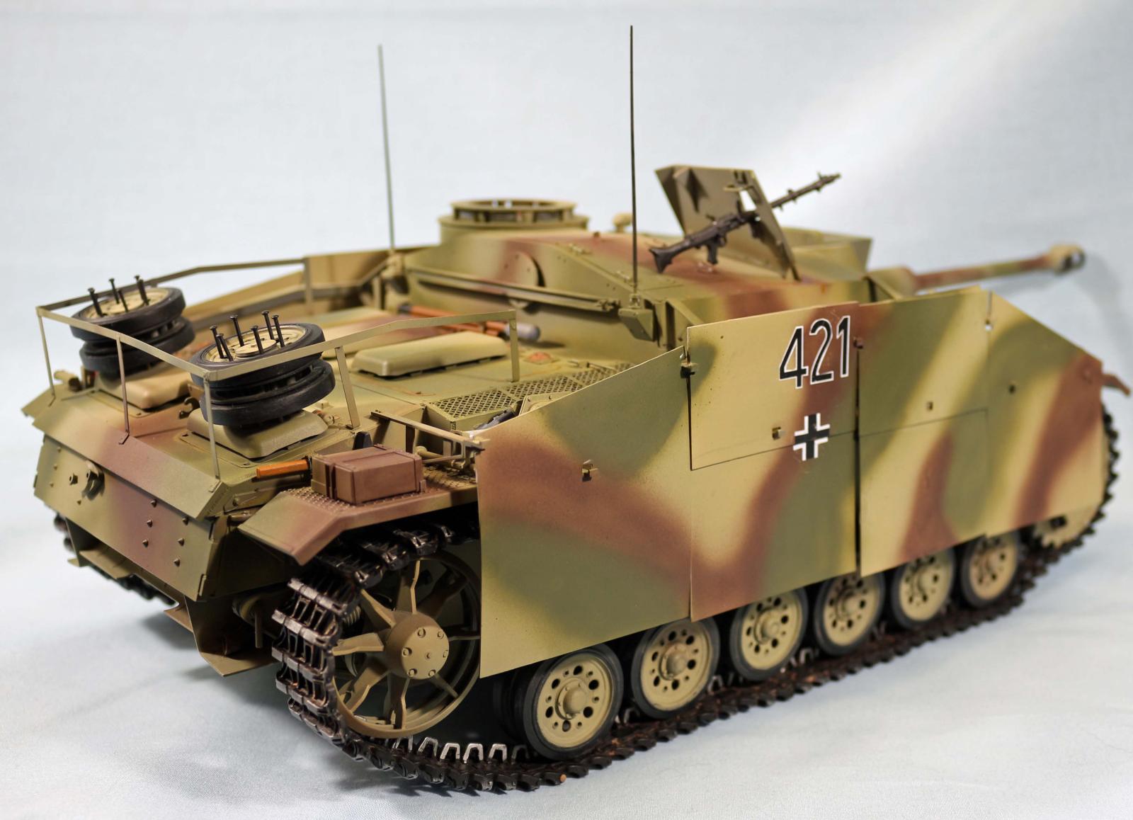
The Sturmgeschutz III was the second most produced German armored combat vehicle after the Sd. Kfz 251 halftrack. It was the most produced fully tracked armored vehicle. It was built on a modified Panzer III chassis replacing the turret with an armored fixed superstructure mounting a more powerful gun. Initially intended as a mobile assault gun for direct fire support for infantry The StuG III was continually modified and was later employed as a tank destroyer
Background
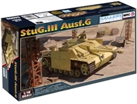
Gallery Models is not a widely known brand and it was apparently acquired by MRC. The StuG III is their newest release and the tooling looks different from what I have seen of photos the Takom 1/16 StuG kit.
The Build
Lower Hull and Suspension
The construction of the lower hull and suspension is made easier since the hull is one piece, all external and internal (torsion bar mounts) are molded into the part. Since this is a key structural part, it made sense and is the base piece for all subsequent major assemblies, (fenders, Fighting compartment, engine deck).
Steps 1, 2, and 3 are pretty straightforward for assembly of the suspension components. The parts fit snugly into the mounting holes in the hull. Steps 4-7 cover round things “The Road wheels, Return Rollers, sprockets and Idlers. All are assembled with a polymer insert, so you could finish them off vehicle as the rollers and road wheels have separate “tire” sections in black styrene. You have options on when to assemble them to the hull. The arms that the shocks attach to , once mounted will make the arm rigid as the shock is fixed and will not telescope, making position1 and 6 on both sides fixed as the torsion bars won’t move.
The Track tension assembly (Step 9) is what the idler wheel is mounted to, this assembly consists of 10 parts and is built up and then glued to the rear hull. There are mounting holes and if you built the Assembly correctly, it should fit with no issues, if not you may have some remediation. On the right side assembly I had some fitment issues and had to file the hull to get the part to line up with the holes. ( R/S Assy Parts. G35,G34,G10, F2, G12 G29,G15,G13,G37, G5) Use plenty of glue as this assembly holds the idler wheel which will hold the track under tension.
Step 10 is simple, but the items you glue here are what the top and back deck mount to as well as the fenders (G1 and G50) the S and N parts are for mounting the fenders and despite the way things look, everything lines up and works. Use adequate glue as these are like structural parts.
Step11 is the rear hull, exhausts and vents and hull access panels. Pretty easy.
Step 12, that is the upper glacis plate and has the two access hatches to drive gear and the headlight then goes onto the front of the hull. I assembled according to the instructions and it looked wrong. (see Pictures) The hinges do not protrude above the deck. So I don’t know if I did something wrong, or it is not right. I can’t fix it now that everything is assembled. If I has spotted this earlier I might have real hinges showing versus something that looks upside down. The hinges on the engine deck look right.
Upper Hull and Decks
Since this is a Stug, there is no turret. The upper hull section (crew compartment) is molded in one piece as is the top front deck (gearbox compartment) and the rear Engine deck. Steps 14, 15 and 16, cover the fenders, and there are a lot of things that go on those, all the tools and tow cables go on before mounting the fenders to the hull. .You can modify this step as you want to and paint and mount the tools after the fenders are mounted. If you plan on mounting the armored skirts there are mounting brackets that you will have to work around to mount the tools, so read ahead and evaluate your options. I followed the build sequence but it was tough to paint the gear trying to maneuver paintbrushes around the brackets and other gear, the Axe on the right is behind the jack and under the hand crank as an example. The tow cables are about 5mm too long as it folds outside the envelope of the fender. I went with 265mm and had to bend and route to keep most of it on the fender. Part G43 and U35 are part of the fender mounting system but has the part with knockout pin holes that need to be filled as those are not under the fender but show outwards to the hull in front.
Step 13 (Pg 11) shows 3 PE parts being folded or bent, Part PE-A12 has a hole in the bottom that the shovel and other locator pins go through. The combination of PE-A7 and PE-A13 are supposed to be bent and linked together to create a linkage that clamps the tool down to the fender and PE-A12. Even though this is a 1/16th scale kit, these parts all together are nearly impossible to manipulate, clamp or glue as a unit. In the end I just glued it to look like a clamp over the parts. This seriously could have been molded in plastic or at least been given an assembly jig.
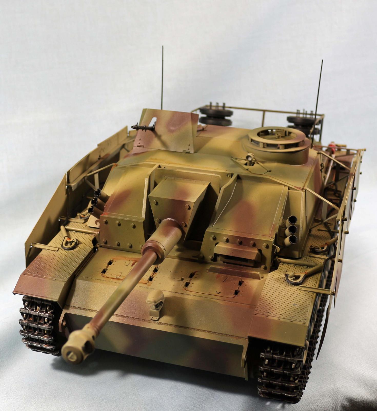
Steps 17-19 are for assembling the cannon and gun mounts. The first choice you need to make is Turned Aluminum or Plastic. To be fair, the plastic part doesn’t require assembly it’s molded as one piece, and naturally it’s big. Most of the gun mount assembly is straight forward but in #17 when gluing R12 and R13 together wait a bit to add Q7 as the items N13, U16 and U17 need to glue to the top of N17 in the cutout that is facing to the rear with N12 facing forward as this will mount to the back of Q9. U15 mounts as one unit to N17 on the bottom, notches also face to rear. Then glue on Q7 look ahead to step 19 as that drawing shows the mount assembled onto Q9 and this will help with orientation of parts. N13 needs to be glued with intent as that joint will hold the weight of the entire gun tube. Let it dry thoroughly and make sure the semi parallel alignment is maintained. On my assembly, the pins on N13 almost perfectly aligned with the holes on Q9. So fit and finish on this assembly was quite nice, everything fit well here.
Step 20 is basic stuff. But Part P2 is the superstructure but the views show that R1 is mounted and that doesn’t happen until step 23Step 21 is where you mount the cannon. Part U27 looks like it won’t support the assembly, it does, but don’t yank it around and it will be fine, if you are not sure you could reinforce it with some Evergreen structural shaped pieces. Make sure the basic part gets a good bit of glue. All of the cannon weight rests on this part. The Part P2 is a bit narrow and the cannon mount is a tight fit. I used a file to widen the gap enough to insert and glue the cannon assembly. I left enough friction to counter balance the cannon weight and you can position it to any attitude you went. I thought this was somewhat odd since almost everything fits pretty nicely, but it ended up being useful for a bit of triteness.
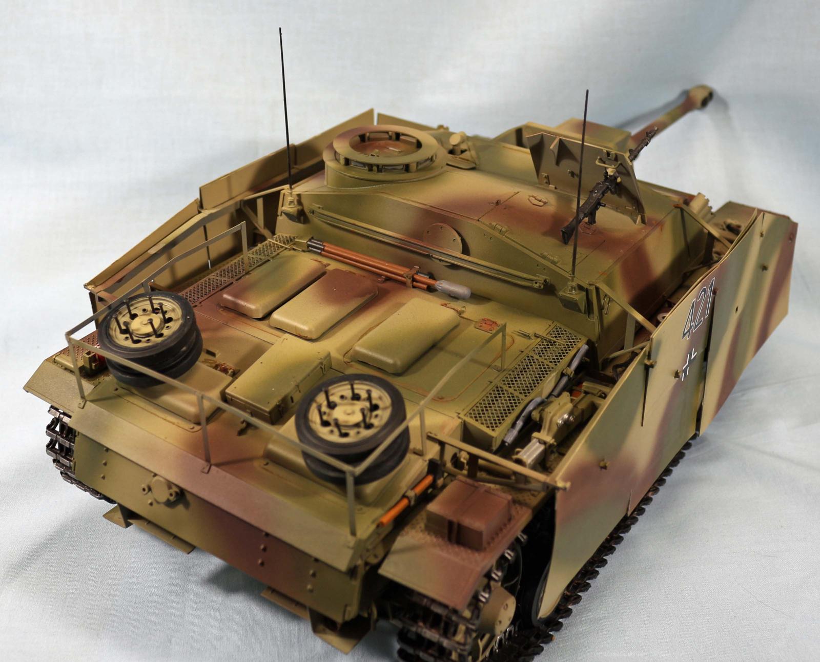
All the items in Step 23 and 24 were added after the superstructure was glued to the hull. I went out ou sequence as This is a big part and al lot of parts would make it difficult to make adjustments in clamping and alignment of the part onto the hull. I was glad I did as the part did not fit well and I had to trim some of the fender that goes under the sponson. This was just enough to keep it from sitting onto the hull without interference. In Test fitting the back deck (step 29) The locating slots were too high and the front would not connect with the hull. The glue joint was essentially a wedge and did not connect. I filed the locator slot bottom down so the engine deck would sit on the hull e3dge level with no gap showing. I could have just cut the tabs off of the deck, but decide these helped to connect and went with that. The instructions show the upper parts being glued onto the hull in step 30. I wasn’t comfortable with that trying to handle his large an assembly with all the smaller items glued onto them already. Nightmares of shearing off parts while trying to align to the hull. You may have better luck, but I am glad I found the fit issues first with my sequence adjustment as that assembly would be very large to finesse it onto the hull with everything attached. This also affected how I painted everything, which I will address later.
The stowage rack on the back deck is all Photo Etch. As big as this kit is, you would think that it could have been done with a sprue, but I think this was probably a cost reducing measure. The side horizontal parts were a bit short, but I wiggled things around on the uprights to get it to fit, but it was tight. Because the rack frame sticks up from the deck so high, in attaching other parts, I kept bumping them and knocking it loose so all the uprights were re glued at least once. Also if you use CA glue to assemble the PE, hit it with an accelerator to get it to set it quickly, this makes it easier to assemble the uprights first and then the side rails.
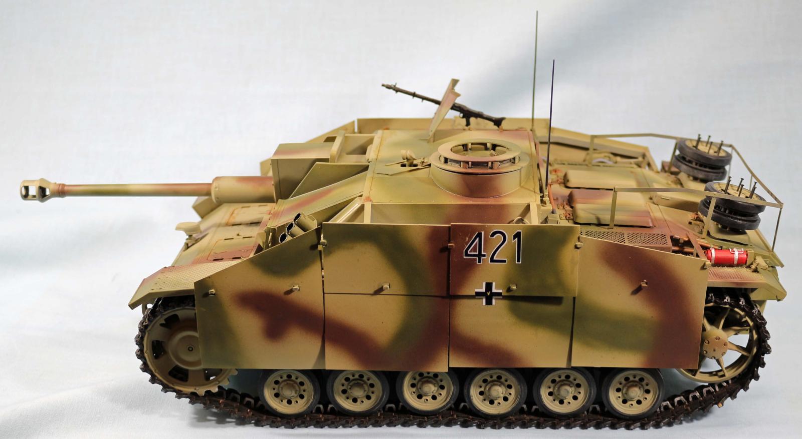
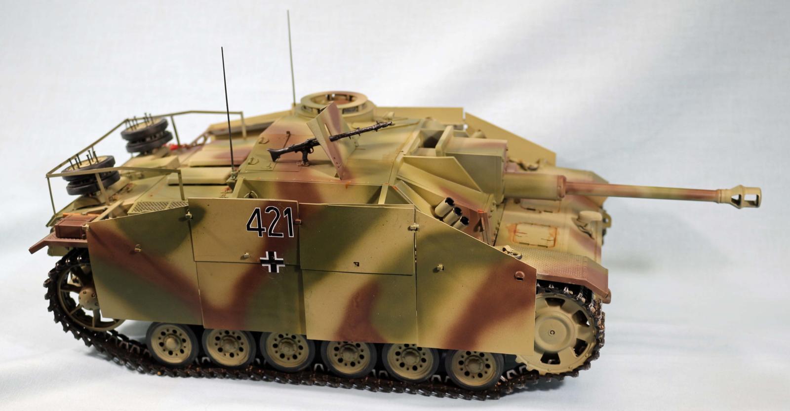
The last step in the instructions is the Side Skirts. There are 6 pieces per side. Four front, rear and center sections with two half sections that cover the middle sections as an additional armor thickness. The skirts have holes punched on the center of the plates and notches that correspond to the mounting brackets. Generally everything aligns appropriately, however the front skirts are a bit wonky on the upper notch like its too short. I was using 5 Minute Epoxy to fasten them and that kept things tight. Your options might be different. The Skirt material seemed to be styrene, but once it hit air after being in a plastic sleeve, it seemed to curl a bit. After priming and painting it with Dunkelgelb, I heated the sheets up and flattened them under some weight and it reduced the curve a bit. Upon final painting of Camo, things didn’t align perfectly, but this also wasn’t a characteristic of the actual vehicle. So skirts being off a bit wasn’t unusual as well as missing skirts was not uncommon. You have a lot of room with these to depict what you want.
The Track
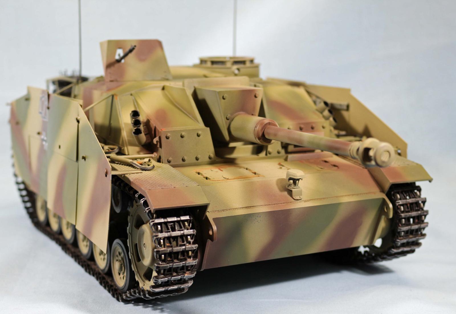
Everyone hates having to assemble individual track links as this means a lot of work. This step is no exception, lots of repetitive work here. However the track blocks are single piece and the pin holes are slide molded and very accurate. The blocks were molded two to a sprue, I cut and trimmed the blocks and made sure they fit and rotated and then took the track pin and assembled them together. You can do this by hand if you push the pin in a small section at a time. If they don’t slide easily check the track block to see if you got the sprue junk cleaned adequately I just fit them by hand carefully as the pins bend easily, I broke several off while inserting and had to fit the broken part after I straightened them out. The center guides have a locator pin that goes into a slot on the block and a flat spot. Both ends need glue and expect to knock them off every so often. That will let you know you didn’t use enough glue. I built 10 block sections with the pins first and then attached the center guides.
I built three 10 Block sections as it requires 91 blocks per side. Having 91 blocks in one long track string makes it easy to paint and weather, the blocks are relatively robust and I made two rolls to save space. You will knock some center guides off, just glue em back on. I actually added one more block for 92 to add a bit of track sag. If you leave the skirts off this looks nice.
Painting and Finish
I approached this kit differently than I usually do. Which is build everything, hit it with primer then camo and weather and detail after the kit is built, but this went together differently. I built the hull and running gear as a separate assembly and then the upper hull and superstructure, so I hit the hull and running gear with Krylon Grey primer. This was followed by spraying the road wheels and return rollers with Krylon Black Primer
Those were then hit with Hairspray before painting with Mission Models Dunkelgelb (MMP 011) The hull with fenders attached, got the Mission Models with Dunkelgelb Coating prior to attaching the superstructure and engine deck. I then masked off the fenders and lower hull before hitting the upper assemblies with Krylon Grey Primer. Once the primer set, I took off the masking and shot Dunkelgelb for coverage and catching thin areas on the lower hull. I also sprayed the road wheels and return rollers to cover the hairspray in prep for finishing the rubber portions.
I chose a color scheme that was for a Stug in Normandy 1944 which had an Olivgrun (MMP-009) and Rotbraun (MM-P012) pattern. .This pattern also had more decals. I wanted more variety visually from this build. I got a bit heavy handed and ended up spraying much wider bands than I wanted, but it looks reasonable. I used a flow aid and drying retarder when spraying to keep this paint flowing as I expected to be painting for long periods of time due to the area. I had to go back and clean up some runs when I hit some areas a bit too hard.
Decals
The decals were pretty basic. The Balkan Cross had flash around it that I cut away. The numbers had one big flash coating covering the letters and would have been a huge area to silver over time, so I trimmed each number individually and place each one and aligned them. They were relatively thick and adhered pretty well. Once placed I covered them with Micro Set to adhere them a bit better. I then coated them with Mission Models Clear Primer (MMS007)
Details
There is not a large variety of extra add on’s in the market. Value Gear has boxes, bundles and stuff for the back deck and the 1/16 scale stuff starts around $25. There are not enough track blocks in the kit to apply as additional armor. Yes, be creative. This will probably change over time.
Weathering
Most standard weathering techniques work, just a lot more physical area you have to deal with. You may have to modulate some things because the physical size will affect how light is reflected
Conclusion
This is an interesting kit. I have never built this big an armor kit. I had a shot at the Tamiya 1/25th Centurion in the 70’s but that is not a big difference from a 1/35 kit. This is a larger jump and it shows, you need more paint, glue, and space to stage and assemble stuff.
Shout out a thank you to MRC, for providing this Stug III kit. They have announced a Panzer III tank Ausf J, L, M in 1/16th scale (Fine Scale Modeler May /June 2022), So some of the build might still apply to those. I had fun building this kit and the market is starting to issue aftermarket items, which will help later in making dioramas in this scale.


Comments
Add new comment
This site is protected by reCAPTCHA and the Google Privacy Policy and Terms of Service apply.
Similar Reviews