
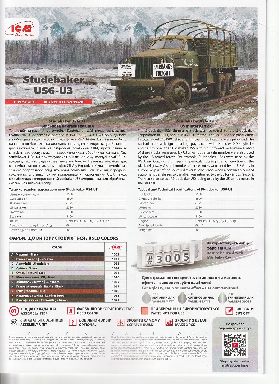
Studebaker US6-U3
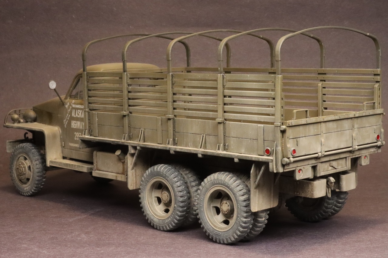
Although not as famous as the U.S. Army’s GMC CCKW ‘Deuce-and-a-half’ the Studebaker US6 trucks were historically important trucks in their own right. Over 200,000 were built by Studebaker and Reo, with the vast majority of these trucks provided as ‘Lend-Lease’ to the Soviet Union and other allies. Although not ‘standard’ in the U.S. Army, many trucks were used by the U.S. Army Corps of engineers and transportation units in building and using supply routes such as the Alaska-Canada Highway, the Ledo Road from India to China, and the Persian Corridor from the Persian Gulf to the Soviet Union. (Tankograd Technical Manual Series #6037 and Wikipedia).
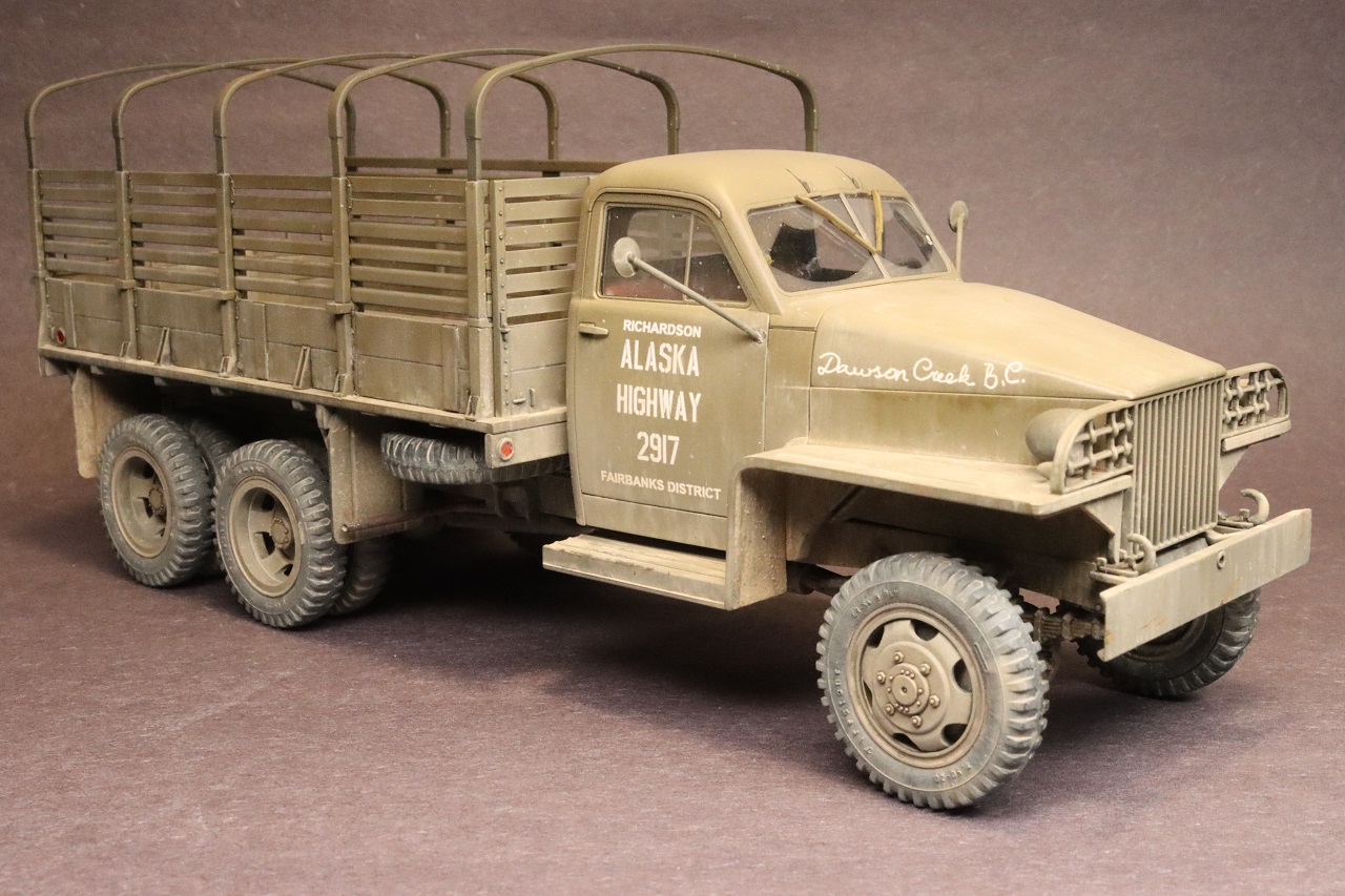
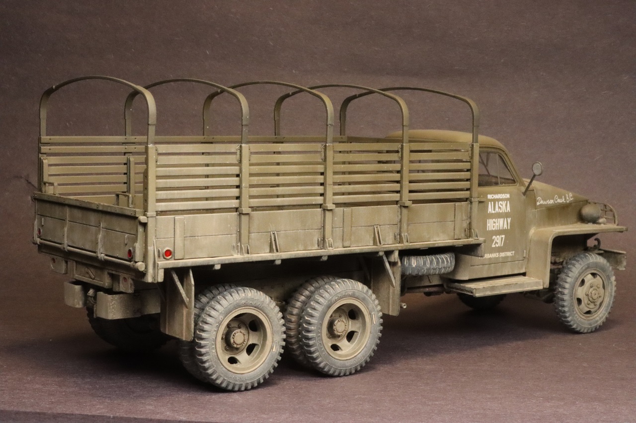
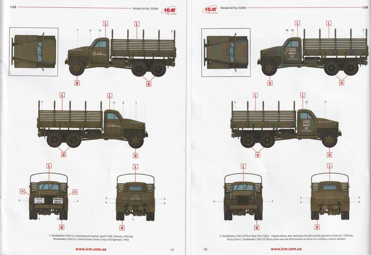
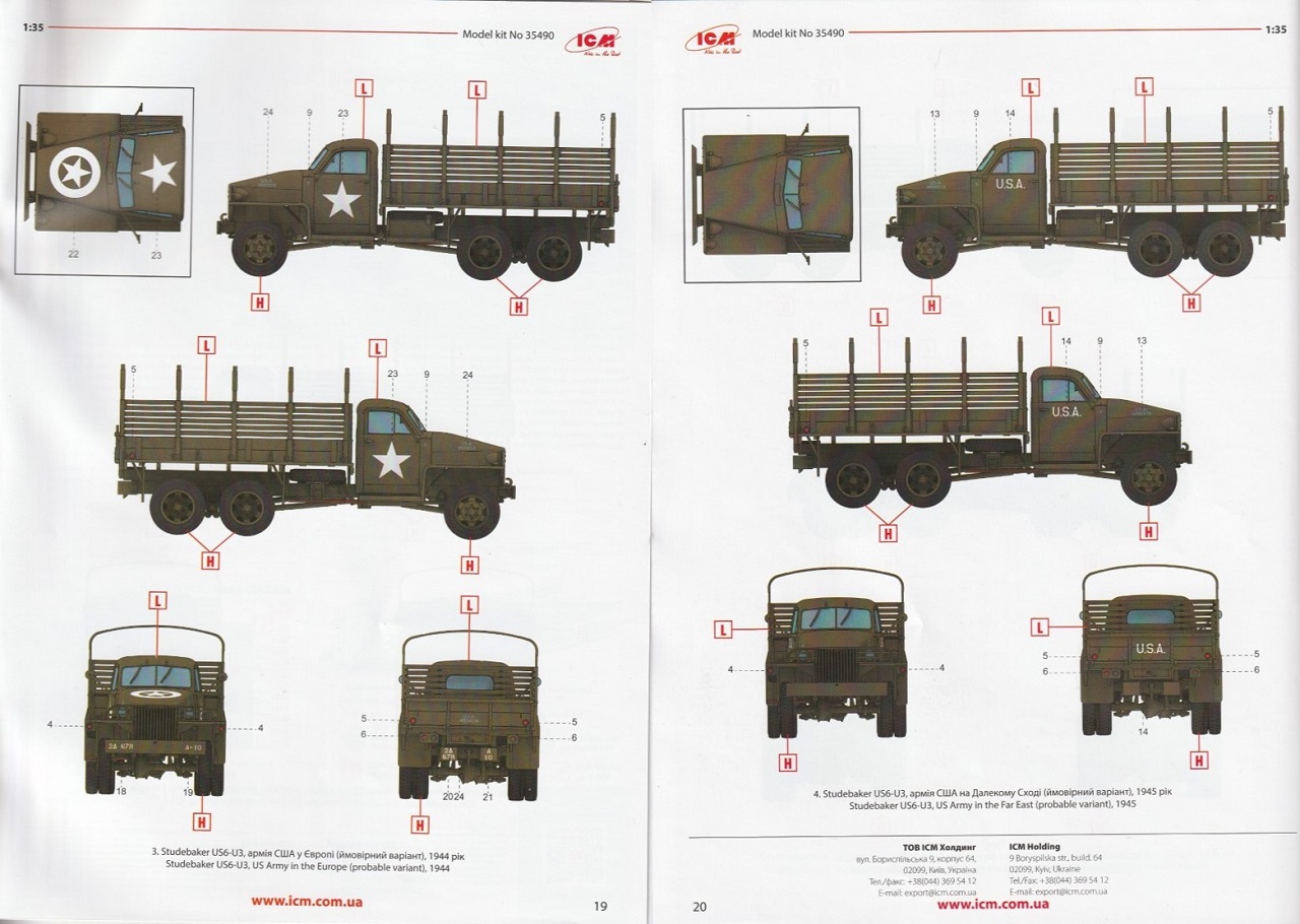
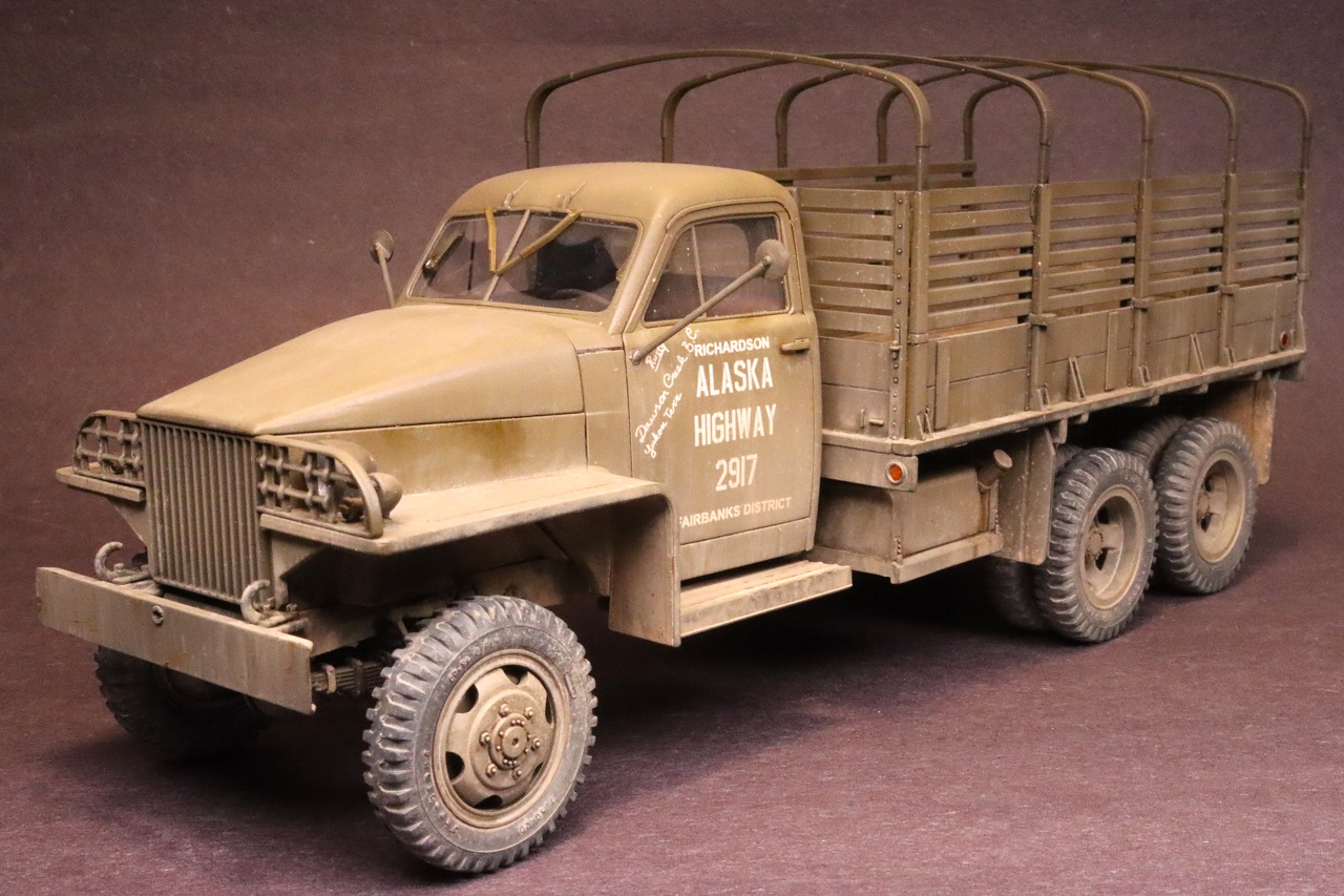
ICM first issued a Studebaker US6 back in 2007.This issue of the kit is a mix of parts from previous issues and some parts newly tooled in 2023. The kit comes in a sturdy plain cardboard box with the artwork printed on a thin cardboard lid. The instructions are printed in color with clear illustrations and are easy to follow. The parts trees come in re-sealable bags. The decals and clear parts are separately bagged to prevent damage. Painting call-outs are keyed to ICM’s own line of acrylic paints. The kit provides four markings options: two for the Alaska-Canada highway, one U.S. Army reverse Lend-Lease truck in Europe in 1944, and one U.S. Army truck in the far east, 1945.
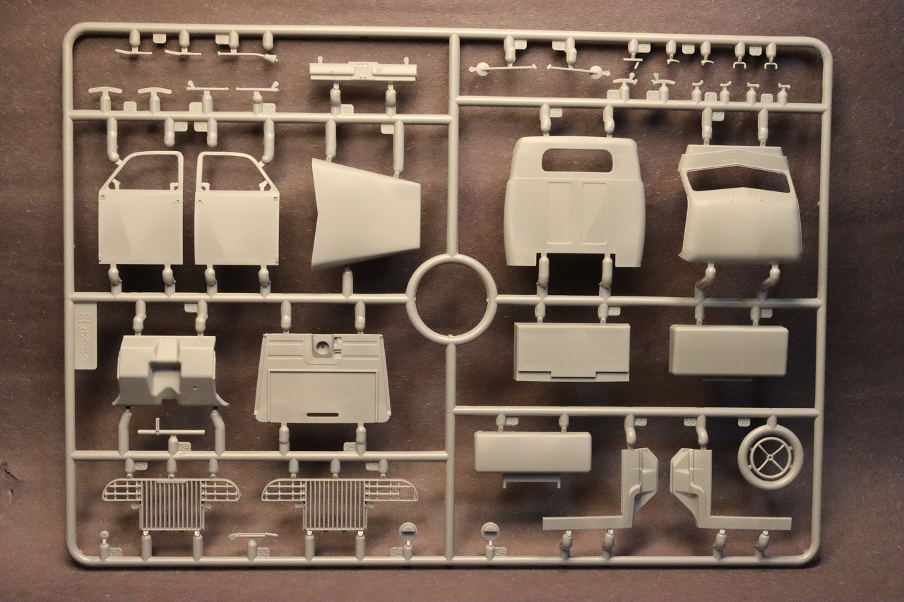
Parts trees A, C, D, and E are carried over from previous editions of this kit. These trees have good detail (including legible tire sidewall data) but the precision of molding is not up to same standard as ICM’s more recent kits.These older trees have sizable mold-parting ridges in some places that will require careful clean-up to get good fits and appearance. Ejector pin marks are mostly hidden, but some are on mating surfaces and interfere with fit.Some parts have spots of rough texture or tooling marks that you may want to smooth out if you are not going to slop mud onto your truck. These four parts trees have no part numbers molded on them. I’d recommend photo-copying pages two and three of the instructions to save the trouble of flipping back and forth between pages. Parts trees B and F are newly-tooled for this kit.
Construction begins with the frame. The frame rails are accurately depicted as C-channel pieces.The inner surfaces of the frame have some raised ejector pin marks. The inner surfaces of the frame have locating aids for the crossmembers that ensure correct location and orientation. I needed to thin the ends of some crossmembers to get them to seat completely.The front crossmember (A76) needs the relief cuts on the upper front corners to be enlarged for good fit. The locating pins for the front bumper brackets (A59 and A60) are too small to be of much use. I found it easier to glue the brackets to the bumper first and then the frame. Make sure the fit to the frame isn’t too snug or forcing it on will bend the bumper.The rear bumpers (A39 and A40) have large mold-parting lines and cleaning them up will destroy the bolt-head detail. I drilled holes where the bolt-heads were and replaced the detail with styrene rod.
The Hercules JXD engine goes together easily and looks well detailed when looking from above. The lower surfaces and sides are simplified but are not easily seen in the finished model. If you want to display your model with the hood up, you will need to add your own hood hinges, a hood prop, and detail to the firewall.
The fuel tank is molded in two halves that are intended to meet in a rabbet-joint. These parts did not fit well and I needed to thin the mating edges to get them to go together.
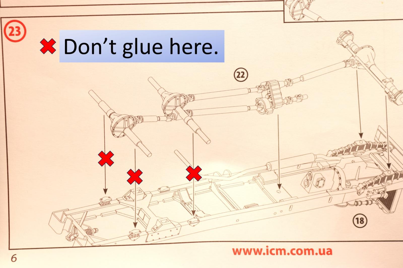
The axle-housings, transfer case, drive shafts, and differential bottoms are molded together as one piece, greatly simplifying construction. The illustration in step 23 seems to show that the rear axle-housings should be glued to the bump-stops on the frame. Don’t do that. Glue the front axle-housing to the front springs and the transfer case to the crossmember, and let the rear axles ‘float’. When you reach the point of assembling the rear suspension (step 25) skip ahead to steps 33 and 34 and assemble the wheels and tires. The one-piece drivetrain is very springy and your axles aren’t likely to be aligned in one plane. By temporarily attaching the wheels you can place weights on the frame while the glue in the suspension sets-up.
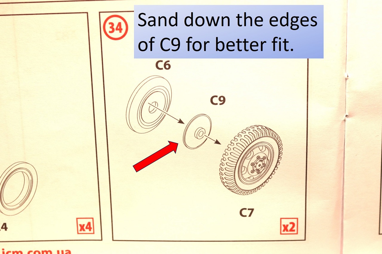
The wheels and sidewall inserts have raised ejector-pin marks that keep the inserts from seating fully. After scraping these marks off, the inserts fit well. When assembling the front wheels, I found that I needed to trim a little material off the edges of C9 to get the sidewall insert to seat fully. The locating holes on the inner rear wheels need to be deepened slightly with a 1.2mm drill to get the inner and outer wheels tightly together. The backs of the wheels are represented as flat discs.The hubs and brake drums are not depicted.
The fit of the engine bay sides (A66 and A67) to the firewall seemed ambiguous to me. I taped the hood to cowl to help me locate and align the bay sides. I also thinned the rear edges of the bay sides to get them flush with the rest of the cab. I’ve heard from other modelers that earlier editions of this kit had fit issues with the cab. This edition of the kit has newly-tooled parts for the cab and clear parts (parts trees B and F). I found the fit of the cab and clear parts to be very good. I sanded the opening for the windshield slightly to get it to seat completely, the other clear parts dropped into place with no additional work. On the full-size truck, the windows in the doors are two pieces: a squarish piece that rolls up and down, and a triangular pivoting vent window. The kit windows for the doors are one piece. So, if you want to have a window open, you will need to cut or replace the kit parts. There is a visible seam at the back of the cab roof but the real trucks have a visible line in the same place. When gluing in the steering column, attach the floor and seat temporarily to ensure a proper gap between the seat and steering wheel. Decals are provided for the gauge faces and placards. The illustration in step 37 might make you think that the gauges are grouped together on one decal. The gauges are actually five separate decals. There is a raised circle on the dashboard just to the right of the steering column that I had assumed to be a gauge. Later, I found there was no decal for it, and the reference photos I found show no gauge in that location. This raised circle may be an ejector pin mark that needs to be removed. This kit’s parts depict the later version of the truck that had the windshield wipers mounted on the windshield frame. The marking option #1 for a 1942 truck would have had the wipers mounted on the front edge of the roof (as shown in the box-art).
This kit depicts the wooden-bed version of the US6. The floor of the bed and its support framing is molded as a single piece. There are some minor sink marks above where the framing is molded. I didn’t bother to fix these, and after painting and weathering the marks are very difficult to see. The underside of the bed has four locating pins and several feed gates that look like locating pins. Test-fit parts E4 and E5 so that you don’t cut off the wrong pins. The sides of the bed can be depicted with the seats raised or lowered. The canopy support hoops and mirrors are very fragile and should be left off as long as possible.
The decals are sharply printed and work well. Decals are provided for the reflectors on the bed but I opted to paint the reflectors on my build.
I found this Studebaker to be an entertaining build. Since many of the parts in this kit date to an earlier era of ICM’s history and require careful clean-up and test-fitting, I can’t recommend it for a beginner. However, anyone with a few vehicle kits under their belt should have no trouble if they work carefully. This kit builds into a good replica of a very historically important vehicle that is otherwise under-represented in model form. I am very grateful to ICM and IPMS/USA for providing this kit for review.

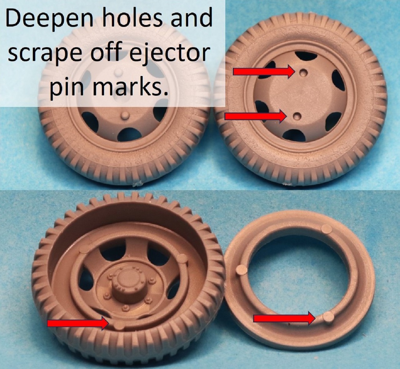
Wheel Modifications
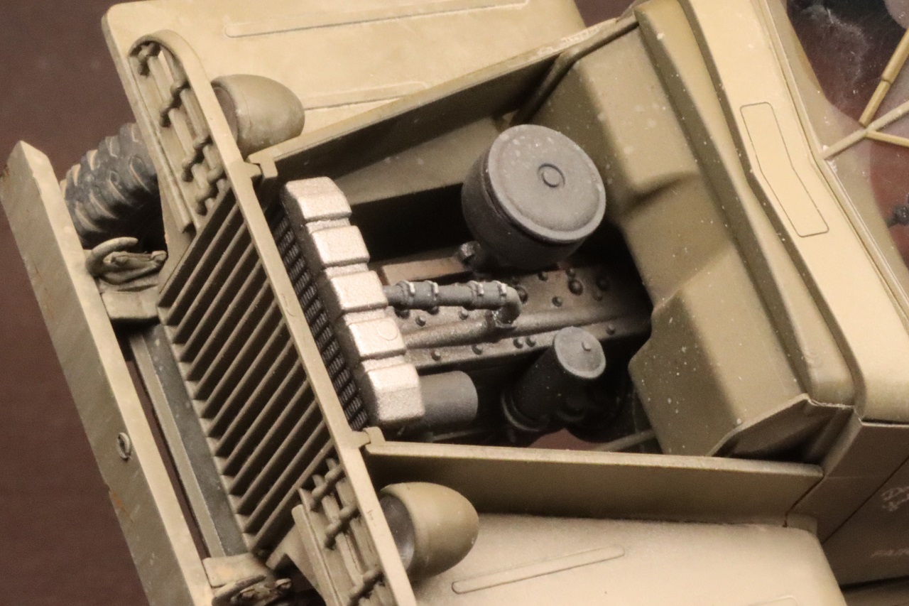
Motor
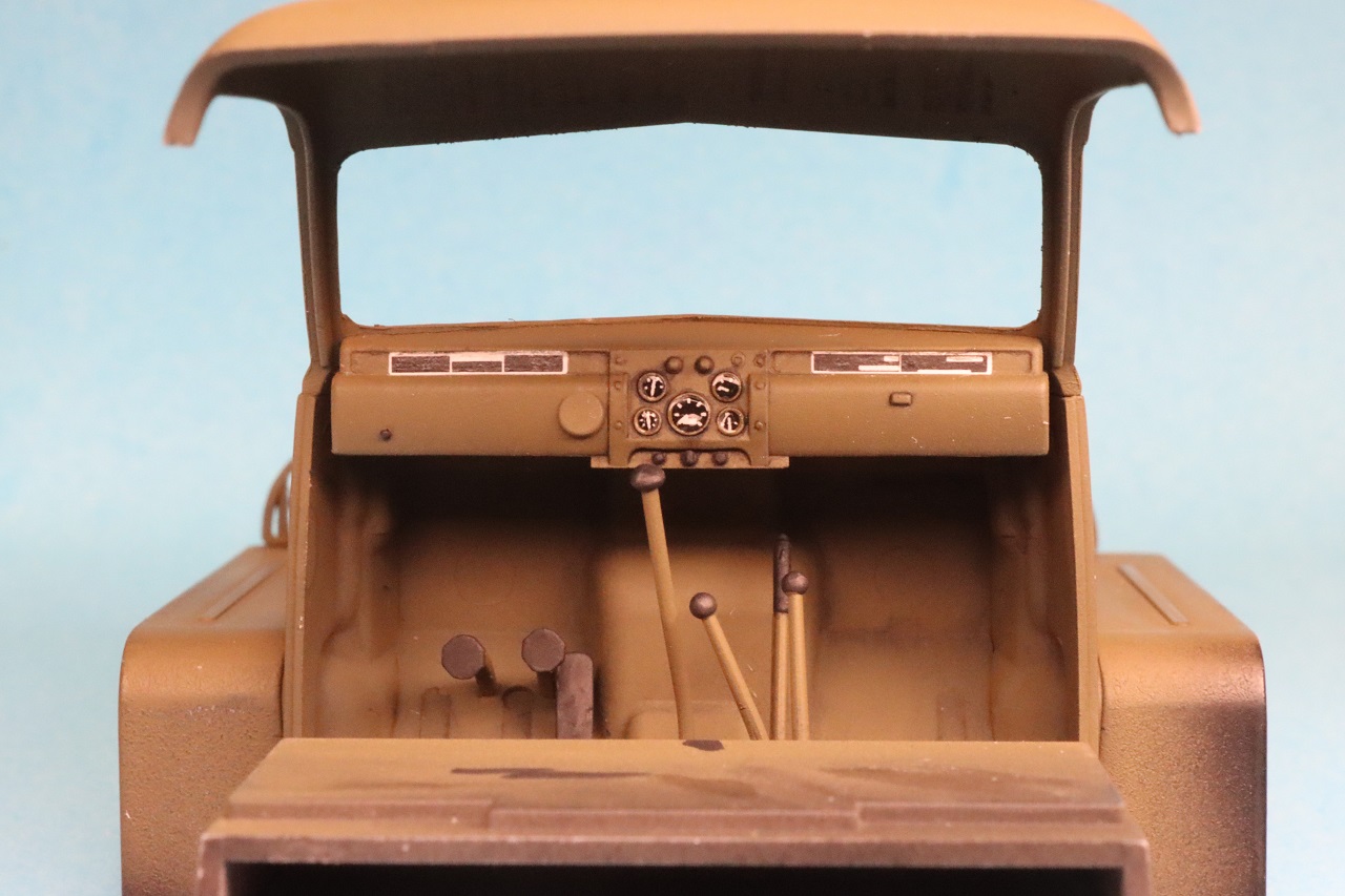
Interior
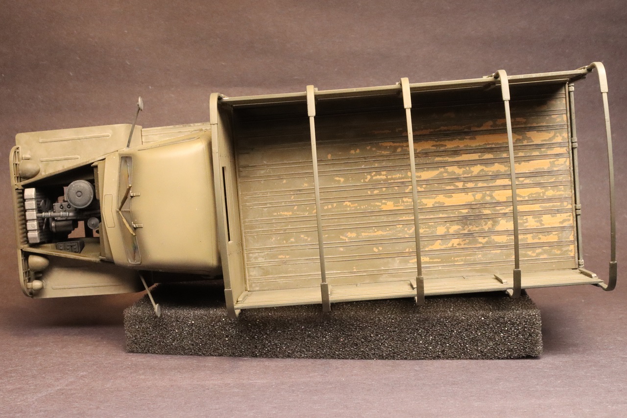
Bed
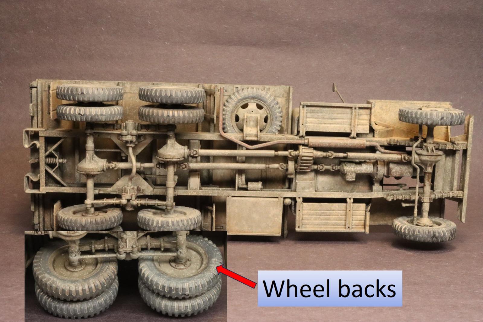
Chassis and wheel backs
Instructiions 1
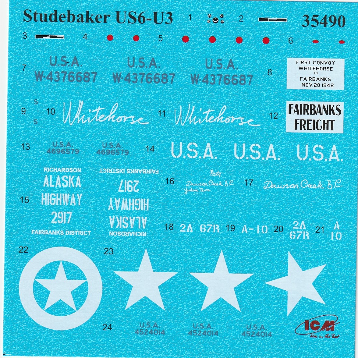
Decals
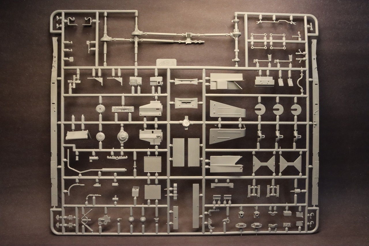
Tree A
Tree B
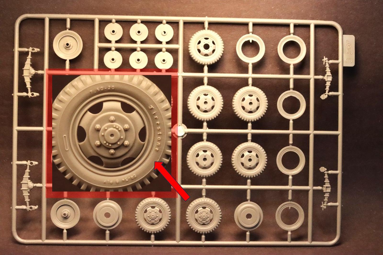
Tree C
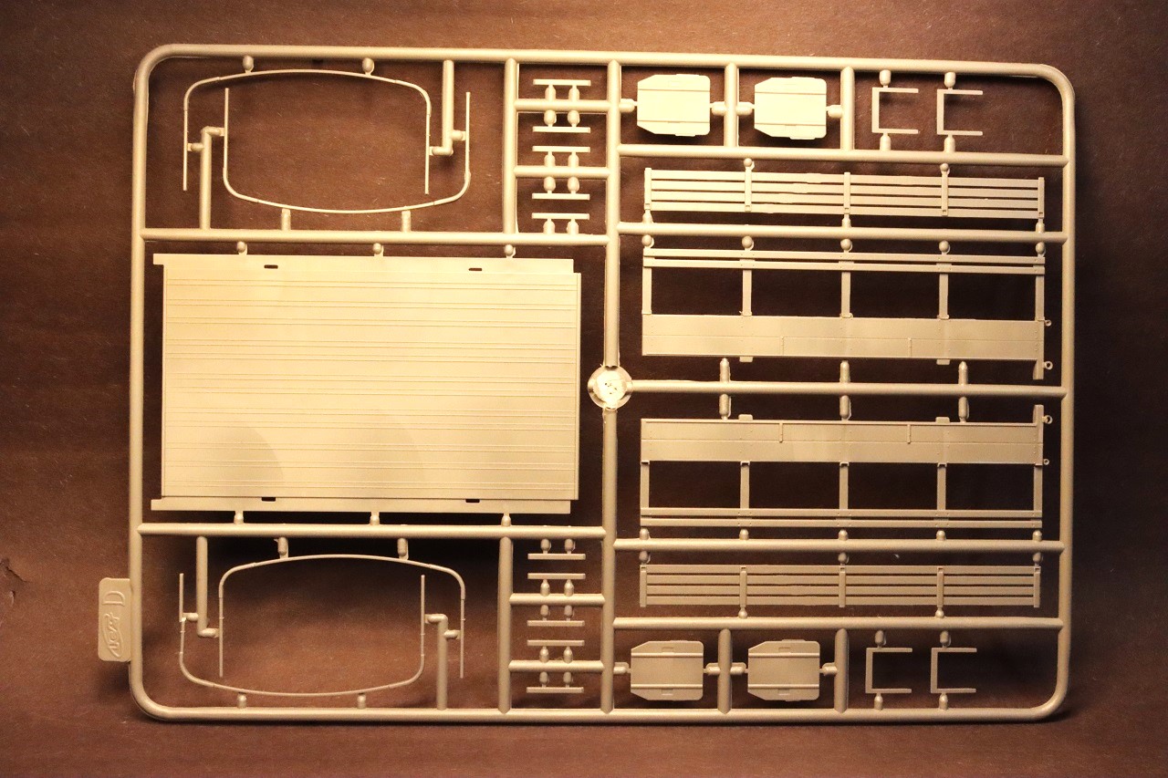
Tree D
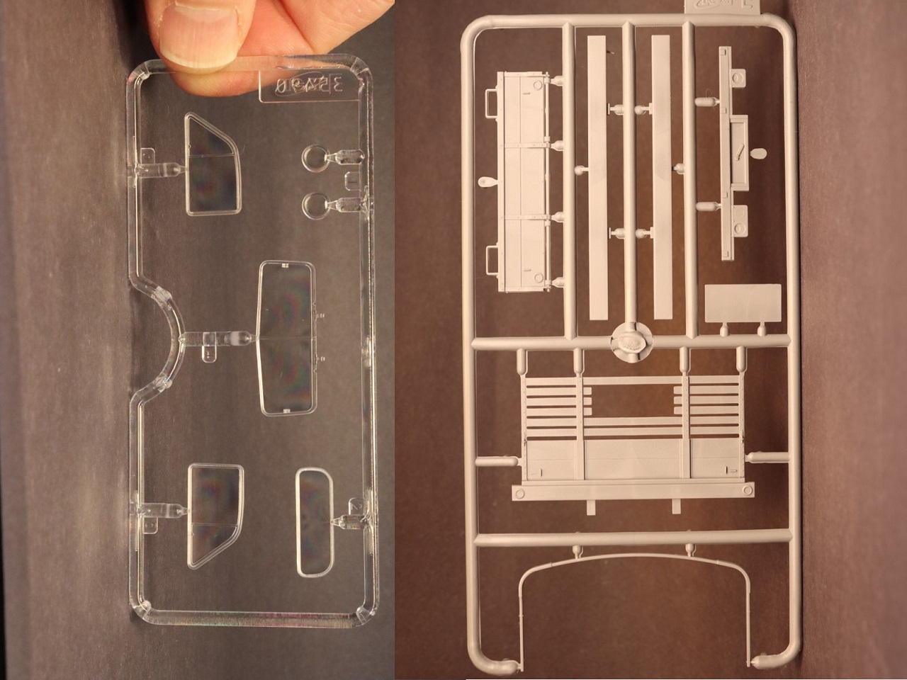
Trees E and F
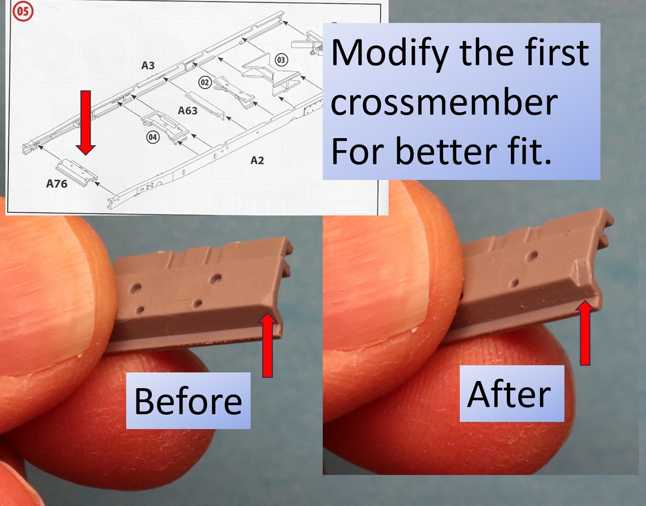
Crossmember Fix
Drivetrain
Front Wheel Modifications
Left Rear
Right Front
Right Rear
Marking and paint options 1, 2
Marking and paint options 3, 4
Comments
Add new comment
This site is protected by reCAPTCHA and the Google Privacy Policy and Terms of Service apply.
Similar Reviews