
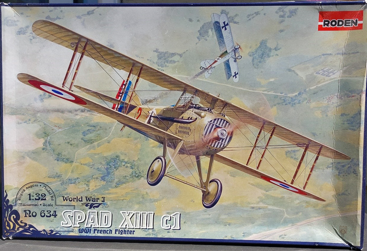
SPAD XIII c1 WWI French Fighter
Summary
Let me start by sending sincerest sympathies to the family and friends of Valery Grygorenko the illustrator for Roden Models. I learned through my local hobby shop that he was killed in the ongoing war in Ukraine
Like most Great War fighters this is a relatively uncomplicated kit. There are some issues that one needs to be careful with during construction, but nothing so complicated that an average modeler cannot overcome. One of the biggest trouble spots was with shallow or limited gluing surfaces. So have your CA cement handy for this one.
Background
In 1916 a new generation of German fighters threatened to win air superiority over the Western Front. The French aircraft company, Société pour l'Aviation et ses Dérives (SPAD), responded by developing a replacement for its highly successful SPAD VII. Essentially a larger version of the SPAD VII with a more powerful V-8 Hispano-Suiza engine, the prototype SPAD XIII C.1 ["C" designating Chasseur (fighter) and "1" indicating one aircrew] first flew in March 1917.
With its 220-hp engine, the SPAD XIII reached a top speed of 135 mph -- about 10 mph faster than the new German fighters. It carried two .303-cal. Vickers machine guns mounted above the engine. Each gun had 400 rounds of ammunition, and the pilot could fire the guns separately or together.
Even though technical problems hampered production until late 1917, nine different companies built a total of 8,472 SPAD XIIIs by the time production ceased in 1919. By the end of the war the SPAD XIII was in use by the French, British, American, Italian, Belgian, and Russian air forces.
The Kit
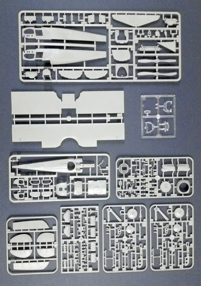
The kit box contains (Photo 1) two large sprues, one with the fuselage and tail and one with the wings; five medium sprues with the engine, landing gear, wing tips and aileron’s, cockpit and fuselage top, and cowl and cockpit items; and, one clear sprue of windscreens. Parts are in a light gray styrene plastic (Photo 2). There are several unused parts that indicate other versions of the SPAD XIII may be forthcoming.
The Instructions
The instructions are two 13" x 38" sheets printed on both sides and folded into an 8 "page" booklet. The front includes a history of the aircraft in Russian, English, and German. The second page includes a parts map for the sprues and construction and decal advice. The remainder of the booklet consists of 21 construction steps and a simple rigging diagram.
Also included is a double-sided color painting and decaling on glossy paper. This sheet has four-view images (top, bottom, left and right sides) for each of the four decal options provided.
Paint colors are for Vallejo Model Color Acrylic Paint only.
Construction
Construction is quite simple and reasonable straight forward. Steps 1 through 7 are for the engine cowling. Step 8 is the upper cockpit, consisting of various gauges. Step 9 is the fuselage top, while steps 10 and 11 are the lower and upper wings, respectively. Step 12 is the tailplane, and step 13 the landing gear. Step 14 is the lower cockpit and engine bearers. Step 15 attaches the engine to the lower cockpit / engine bearer assembly and attaches this to the lower wing. Steps 16 and 17 construct the right and left fuselage sides, respectively. Step 18 builds the fuselage around the lower cockpit/engine assembly and lower wing. Step 19 attaches the tailplane and vertical tail to the fuselage. Step 20 places the struts and attaches the upper and lower wings. Step 21 completes construction with addition of the propeller, landing gear, and tail struts. The lower part of Step 21 is a rigging diagram.
Paint callouts are shown throughout the instructions as black circles with a white letter. You’ll need to refer to the color sheet for the appropriate colors.
I started this kit as I do all my builds. Washing the sprues in warm water with dish detergent and scrubbing the parts with an old toothbrush. I then primed the parts while still on the sprues with Krylon Fusion All-IN-One Matte White Paint.
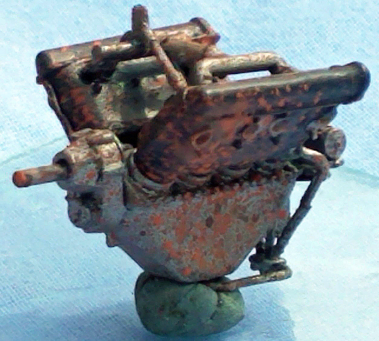
Construction begins with construction of a fairly detailed Hispano-Suiza engine. Pay close attention to what parts on Sprue Z are not used as the unused engine block on this sprue is very similar to the one on Sprue A. This little beauty includes most of the plumbing. Only wiring need be added for super-detailing. The biggest negative about this six-step process is that it will be completely hidden when the fuselage is constructed. One could leave some parts loose to show off the engine and cockpit with a little work.
Step 8 builds the upper cockpit deck that holds most of the flying gauges. The detail of the gauges themselves is fat, consisting of raised dials and bezels. However, with careful dry-brushing they don’t look too bad.
Step 9 builds the fuselage top. I only attached parts 19D and 20D until after painting the fuselage (it was easier than masking later). Step 10 adds the wing tip ends to the lower wing as well as some of the cockpit plumbing on the floor.
Step 11 adds the wing tip and ailerons to the upper wing. Pay extra attention to wing top and bottom, as unlike the lower wing, the image is not very clear. The image in the instructions is showing the bottom of the top wing.
While steps 12 (the tailplane) and 19 (the vertical tail) are straight forward the attachment points of parts 23A and 18A are really small. There are only four to attach the rudder (18A) to the tail, and six to attach the stabilizers (23A) to the horizontal tailplane. This is a good place to use CA cement to get the strongest bond possible.
Step 13 and 14 are also straight forward. Be careful with the axle assembly (Part 19A) as the axle ends that go through the struts and into the wheels are fragile. I had the sand down the axles and strut openings to get them to go through the struts. I’m sure this contributed to later breaking off both wheels at different time. In the end I drilled the axle assembly and the axle piece in the wheels and attached them with wire.
For Step 14 I built up all the parts that were to be painted natural wood and the painted it as a unit, before adding the Steel parts.
Step 15 attaches the engine to the cockpit/engine bearer assembly and attaches that to the lower wing. The attachment of the engine to the engine bearers is rather tenuous, so I used CA here too (after using two different liquid cements and having it come loose both times).
Nothing special construction wise with panels (Parts 2C, 3C, 6A, and 7A). The color guide shows them the same color as the fuselage. I went with the color guide, assisted by images from the internet that also showed them as matching the fuselage.
Step 18 builds the fuselage around the cockpit/engine assembly on the lower wing. I attached the two sides to the lower wing and then added the fuselage top. Were I to build this again I would attach the fuselage top to the sides first, then attach that to the lower wing assembly. Also note that, as in Steps 16 and 17, the lower engine covers are called out as steel in the instructions, but shown as the fuselage color on the color sheet. I built the exhausts at this point, but left them and the cowling front off until after painting the fuselage.
Nothing of note in Step 19 other than the previously mentioned small attachment points of the rudder to the vertical tail.
Step 20 joins the upper and lower wing with the various struts captured between them. This is where I really went off on a tangent. I knew it was going to be too much to paint the fuselage/lower wing assembly, the upper wing, and the struts before attaching them together. One positive note here is that the struts all have the rigging attachment point molded on. With careful drilling one can open them up to thread the rigging through.
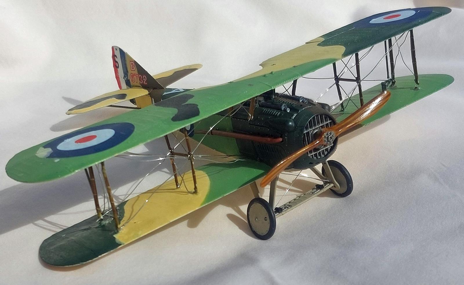
This step is where I also encountered the largest negative I have for this kit. The strut attachment points are mere dimples in the upper and lower wings, so the strut attachment is tenuous at best. I used massive amounts of CA before getting them to stay in place. By carefully aligning the top wing while the struts are glued to the bottom wing, I was able to do all the rigging without the top wing in place. This made for a much easier rigging job. As one can see from the attached photographs my rigging skills are pretty poor. I tried using fine wire, but kept having one or more of the struts come off while tensioning the wire. Were I to do this again I would solidly CA the struts and then use thread for the rigging.
Step 21 completes the build with the attachment of the undercarriage, tail struts, and propeller. Pay attention as there are two propellers on Sprue A.
The lower image in Step 21 is a rigging diagram. I read an online review that noted large discrepancies with this diagram and the real aircraft. So to accurately rig this model you’ll need good references. The most telling omissions are the control lines to the rudder horns, the lines from the top of the cabane (fuselage) struts that meet at the center of the fuselage top, and the fact that the diagonal lines from the top of the outer struts to the top of the bottom wing are actually doubled lines. I added the double lines, gave up trying to get the cabane lines, and haven’t placed the rudder lines as yet.
Painting and Finishing
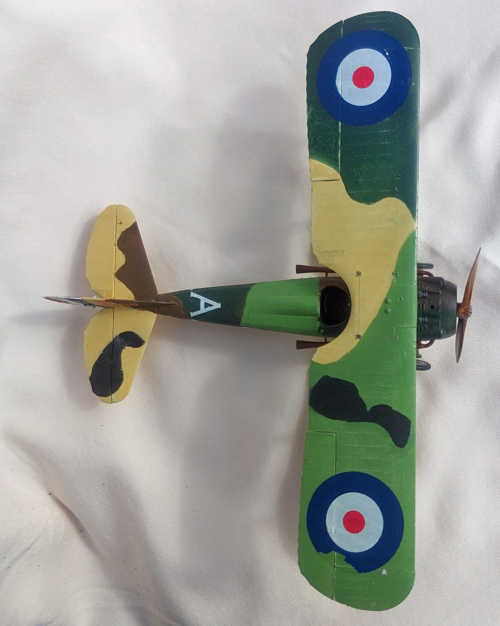
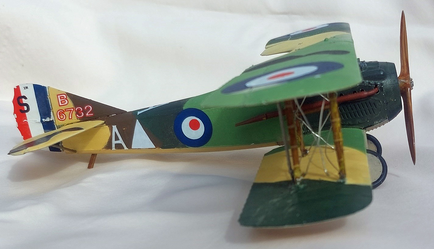
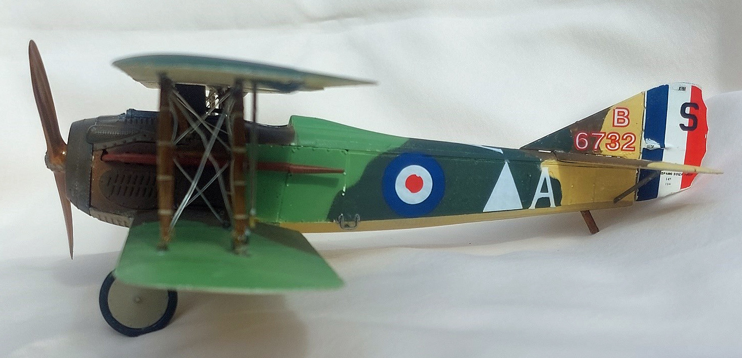
There are four paint/decal options. Two Italian aircraft, one French, and one British. I chose the British aircraft as I liked the camouflage. The four-color view sheet and the box side note the serial number, squadron, pilot, and theater of operation for each aircraft. I thought the inclusion of this information was particularly educational.
Engine and Cockpit Interior: Because of the dark finishes I went back and reprimed sprues D, E, and Z with Krylon ColorMaxx flat black primer.
I built the cylinder heads (Steps 1 and 2), leaving off part 16Z, and painted them flat black. I built the engine block (Step 5) and airbrushed it, along with the other engine parts steel. I finished assembly of the engine and weathered it by splattering two shades of rust Lifecolor Matt Rust 1 and Matt Rust 2) onto it. I also added engine oil and fuel stains from AK Interactive (Photos 3 and 4).
For the natural wood components of the upper cockpit, cockpit/engine bearer, interior bracing, tail skid, and struts I used a method described in Airplanes in Scale Vol III from Accion Press. The first step is to pant the part a generic light color. Different type of wood can be simulated with different base coats. I used Tamiya Dark Yellow (TS-3) from a spray can for the cockpit and interior parts and tail skid, and Tamiya Yellow (XF-3) for wing and tail struts. After allowing this coat to dry for 24-hours I applied a dark oil color creating streaks (wood grain). I used Burnt Umber on the Dark Yellow parts and Burnt Sienna on the yellow parts. After letting the oil paint set-up for about 20-minutes use a sponge to wipe off some of the paint, creating a wood grain. Allow this oil paint to dry completely (one to two days) then apply a coat of clear orange to the entire piece.
For the dials in step 8 I painted the parts as noted in the instructions and then used careful dry-brushing to paint the bezels brass, and the dials and faces white. Review of internet sources also helped with proper colors. Part 11D (Step 9) is noted as steel in the instructions, but review of sources show it to be copper.
Camouflage Coat: After building the fuselage in Step 18 and adding the tail (Step 19) I started exterior painting. For the exterior colors I used Tamiya Deep Green (XF-26), Vallejo Model Air Camo Medium Brown (71.038), Pale Green (71.095), and Vallejo Model Color Beige (70.917) (Photos 5 through 10). I started by roughly spraying the areas to be beige (70.917). This was masked and followed by the pale green (71.095). After drying overnight, I masked and sprayed the dark green (XF-26). Again, after drying overnight, I finally masked and sprayed the dark brown (71.038). As noted earlier I sprayed the metal parts noted in the instructions as being steel the same color as the fuselage in that area.
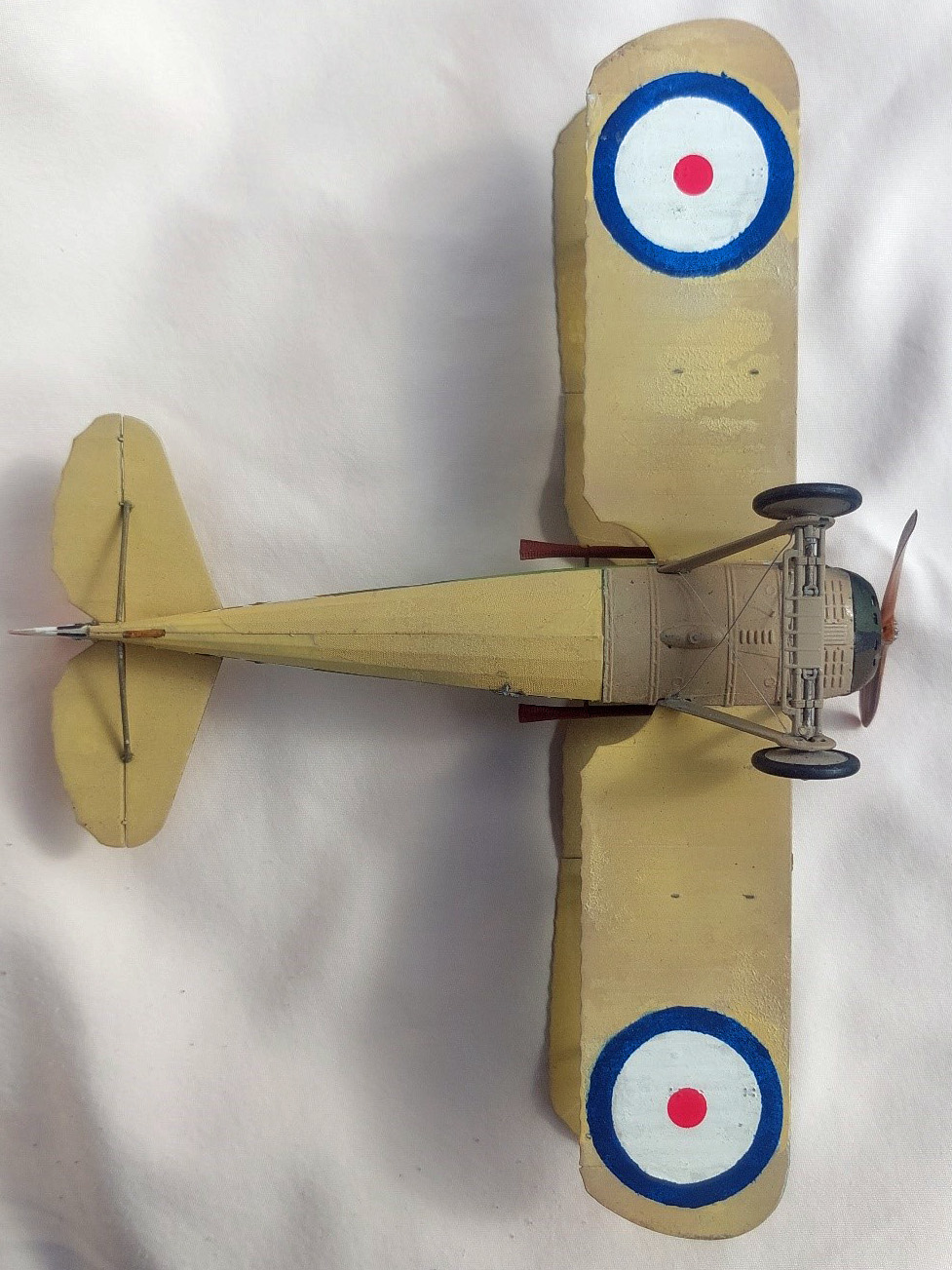
For the undersides of the fuselage, wings and tail, I used another method from Airplanes in Scale. I first sprayed the natural linen areas with Tamiya Wooden Deck Tan TS-68 from a spray can. After this dried overnight I sprayed Vallejo Beige (70.917) through a stocking. The stocking imparts a fine pattern that, in this scale, looks quite a bit like linen fabric.
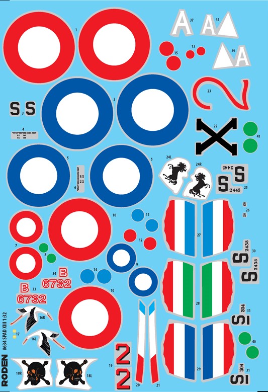
Decals: Because of the models scale the decal sheet is quite large (Photo 11). I used the Red and Blue MicroSol/MicroSet products to apply the decals without any problems. Decals were applied over a Humbrol Enamel Gloss Varnish (35). This was applied to the whole model. Once the decals were dry, I gave the entire vehicle a coat of Humbrol Varnish Flat (49) to seal the decals and prepare the surfaces for future weathering.
The decals all went on without any issues and settled down nicely into the fabric texture of the fuselage. Double check the decal numbers against the model. For the RAF version I chose I found out too late that wing top and bottom roundels were reversed. The top wing is slightly larger than the lower wing, so the large roundel (decal no. 5) goes on the top wing and the smaller roundel (decal no. 2) goes on the lower wing. I had applied the smaller roundel to the top wing so I had to mask and paint the lower wing roundels.
Conclusion
This kit builds up into a very nice model of this iconic World War I fighter aircraft. With a low-parts count it is an easy and quick build. I spent most of my time with painting and rigging. One word of caution is required, some part number and decal numbers are reversed, so pay careful attention to what the part looks like and how and where it attaches.
I would like to thank Roden for providing this kit for review, and to IPMS USA for giving me the opportunity to build it.
Comments
Add new comment
This site is protected by reCAPTCHA and the Google Privacy Policy and Terms of Service apply.
Similar Reviews