
Sd.Kfz. 2 Kleines Kettenkraftrad Typ HK 101
Background on the vehicle is provided in English, German, Spanish, Italian, French, and Russian. Colors are called out in Italeri acrylic paint numbers and some in RAL numbers. Detail color references are included in the various assembly steps. Diagrams of each of the sprues are included, which is important as the parts are not numbered on the sprues themselves. The sprue letter is only called out on the diagram, not the actual sprue. Identifying the correct part will require referring to the sprue diagrams to see the number and where it’s located on which sprue. I made copies of the sprue diagrams to tape up in front of my workbench for quick reference. I also added tape tabs to the sprues with the sprue number to make it easier to find the right sprue.
Hull Assembly
The first series of steps assembles the Kettenkrad’s tub, suspension, and wheels. The suspension arms are not glued as they have a press fit, and small springs allow the suspension to flex. The kit parts for the suspension arms, 180G, have small holes, which I assumed were for the spring, although this is not indicated on the instructions.
I was uncertain about the location of parts 172G and 161G on the inside of the side panels as there are no marking locations. These parts support the engine, but their exact location is not clear. In step 3, the side panels, front panel, and floorplate don’t fit together very well and create some large gaps in the exterior corner joints that required filling. Otherwise, the rest of the hull parts fit together OK. Also in step 3, the tow hooks are shown to be installed in the wrong location. They should be at the top of the curved front portion of the floor, part 6A.
In step 4, the numbers for the wheels are misnumbered. The fore wheel should be 22C and 21C, wheel #1 should be 23C and 24C, and wheel #2 should be 19C and 20C. There was lots of flash to clean up on these parts, and I roughened the rubber wheel treads for wear texture.
Step 5 assembles the side gas tanks and storage compartments. When installing the side tanks, use part 215H in step 15 to get the correct spacing of the tanks. There are some nasty ejection pins on the underside of the storage covers that need to be removed if the covers are to be visible. There is no lid provided over the battery as in the actual vehicle.
Engine
The next series of steps build the engine, which consists of 107 parts. The engine is a nice subassembly and lends itself to additional detail with ignition wiring and fuel piping.
Interior
The interior of the vehicle has the transmission cover, but no transmission is included with the kit. Rubber parts are provided for the seat and knobs on the levers. There is also lots of flash on all of these parts. Decals and clear lenses are provided for the instruments on the dash panel. The Dash is misnumbered as 162F and should be 162G.
The engine and rear cooler enclosure are installed in the vehicle tub in step 10. There are some ejection pins on the damper for the cooler that need to be removed if the damper is to be operational. There’s not a real clear and stable mounting location for the engine. Use the exhaust pipe connection to the heater/cooler and locate the engine as far back as possible to avoid problems fitting the hatch cover.
A rubber pipe is shown connecting to the carburetor, and then gets installed to the handlebar in step 13. There is no routing shown between the two. From reference photos, this cable should run along the top of the bevel on the right interior side panel and through the front of the hull.
The shift gate for the gear lever is a prominent part of the front dashboard, but none is provided with the kit.
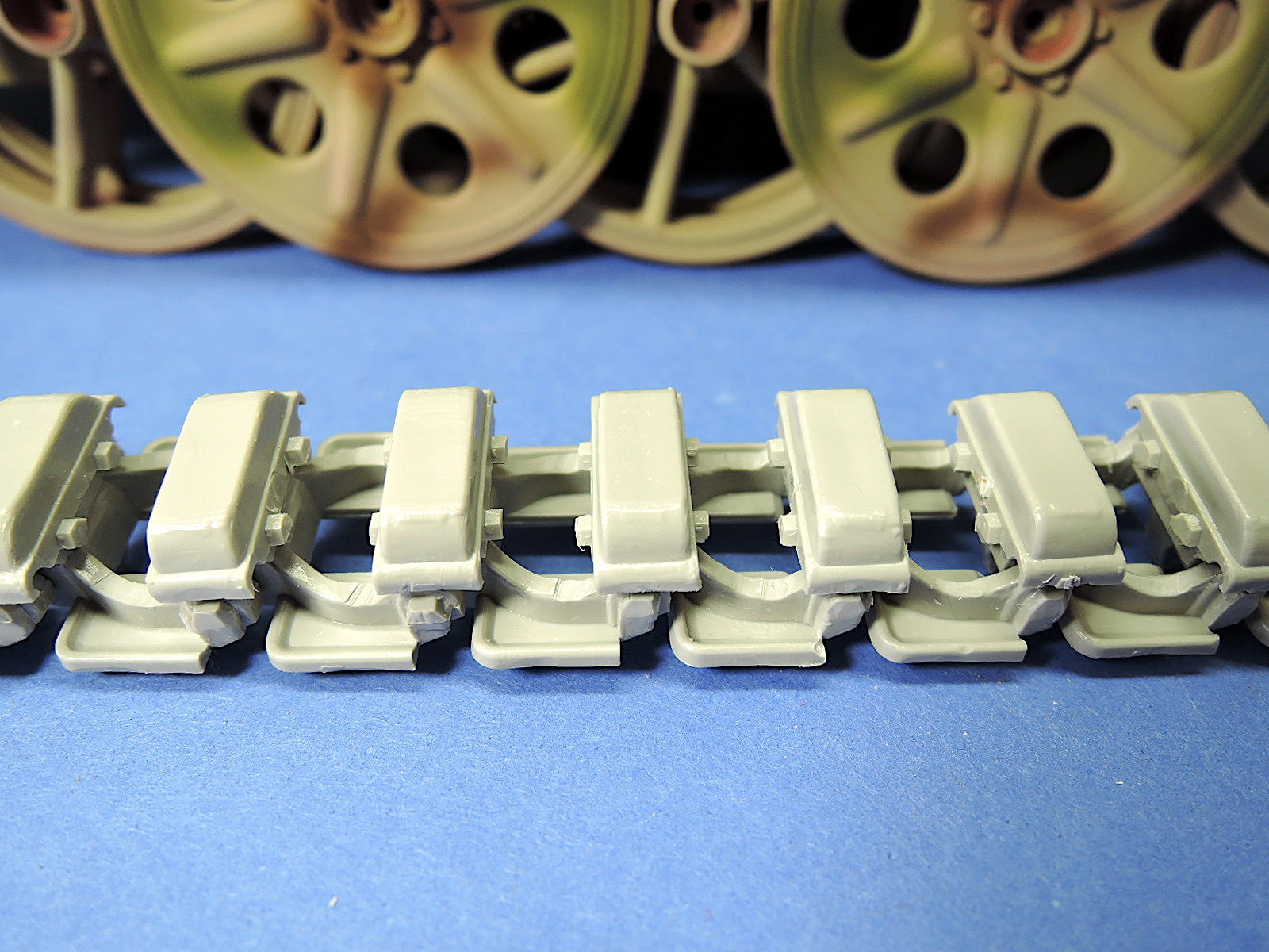
Treads
The tread links are comprised of two pieces, and there are 42 treads on each side of the vehicle. There is a large amount of flash, misaligned forms, and ejection pins that require intensive cleanup of the tread parts. With careful gluing, the treads are very flexible when completed.
Front Fork & Wheel
The Front fork is a complicated assembly, so care needs to be taken in following the instructions. The fork sections are two halves and the injection pins need to be cleaned up so the halves fit together properly. In step 12, parts 29E are the brackets for the handlebar. Refer to subsequent step 13 to get the correct angle for these brackets. The clamps on the brackets are misnumbered as 31E and should be 30E. Pay attention to those parts indicated not to be glued as they will allow the fork to be mounted on the tractor later on.
In step 13, both parts 51E should be mounted inside parts 65E, not as shown. I found it easier to install parts 34E, 40E, 44E, and 54E after the fork is installed to the hull with part 64E.
The rubber pipes E and C are installed in the small hole in the front of the tractor hull as the front fork is installed.
The vinyl front tire has nice detail with the sidewall lettering and minimal seam on the tread. I just used a sanding stick to show some wear on the tread and highlight the lettering.
Engine Hatch and Rear Seat
The engine hatch has an interior frame and vinyl mesh that cover the engine. The mesh fits together well, but the whole hatch doesn’t fit very well. I had a conflict with the air cleaner on the engine obstructing the hatch, so the engine probably was too far forward. The side fuel tanks were too far apart for the hinge panel 215H, so I had to clamp the tanks while installing the hinge part. The rear seat panel did not fit very well either, and I broke one of the pins trying to get it installed. Vinyl cushions are provided for the seat and backrest.
The rear electrical panel is not the right shape. It should have a panel covering outlets for trailer electrical connections. The color marking options show a different, more correct configuration with the outlet panel and reflectors, but this is not included in the kit.
Mud flaps for the treads are installed in step 15. Both of the anchor brackets should be part #233H. The brackets are angled, so make sure to orient them correctly so the mud flaps hang vertically.
Accessories
Included in the kit are accessories including 3 German Stahlheim helmets, canteen, cooking pot, and several tools and a small cable for the storage area below the seat. A German MP40 ‘Schmeisser’ with a vinyl strap is also included.
Summary
This kit has many errors in the instructions, lots of flash and misaligned molding, missing detail, and errors in details that detract from the kit and make for a difficult assembly. It can be made into a quality model with lots of clean-up work, correcting details, and adding scratch built pieces. The large scale of the Kettenkrad kit means there aren’t a large number of small parts.
I recommend this kit only for more experienced modelers who are willing to put up with the extra clean-up and can make the modifications necessary to get everything to fit. I still enjoyed building this large kit, and with some scratch building and additional detail, it can make a nice model of the Kettenkrad.
Thanks to Italeri for releasing the kit again, and to Hobbico for providing the review sample to IPMS.


Accessories for Kettenkraftrad
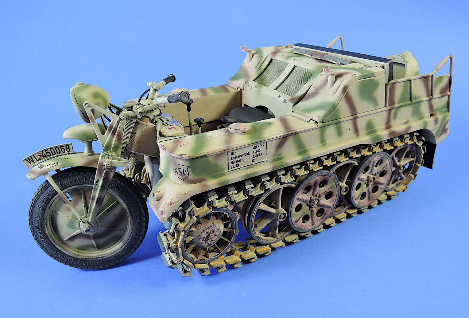
Finished Model of Kettenkraftrad
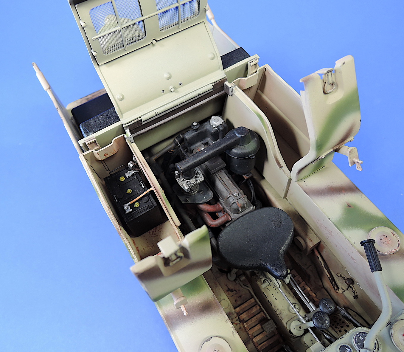
Kettenkraftrad engine compartment
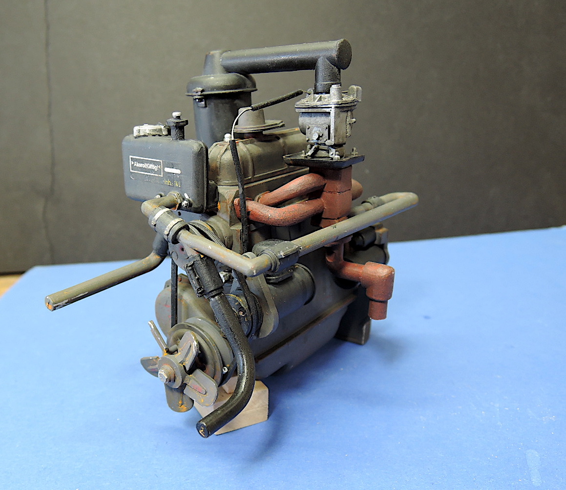
Engine assembly for Kettenkraftrad
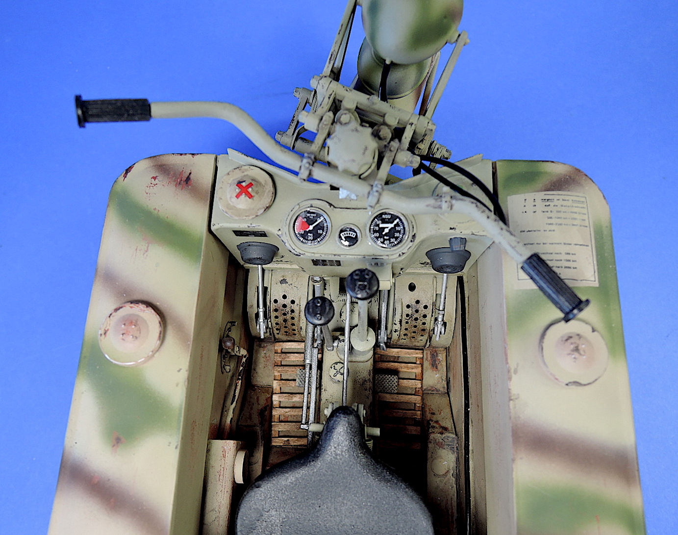
Interior for Kettenkraftrad
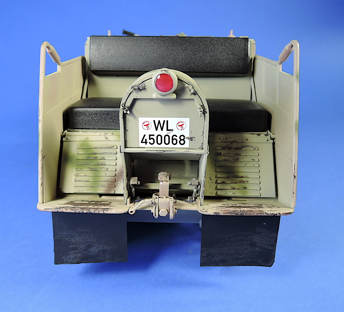
Rear end of Kettenkraftrad
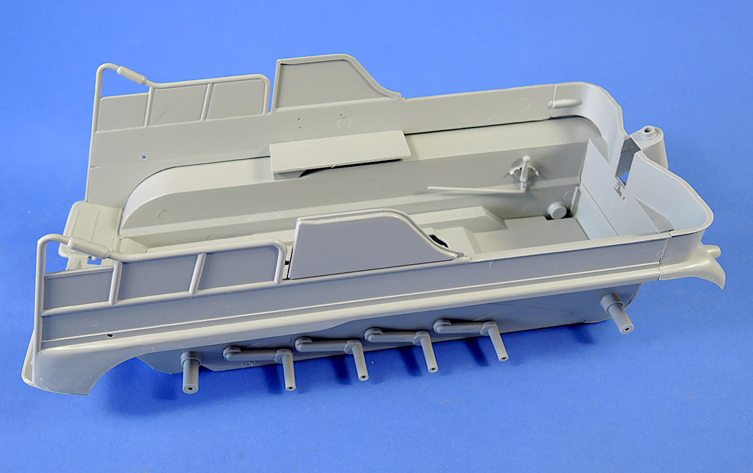
Chassis of Kettenkraftrad
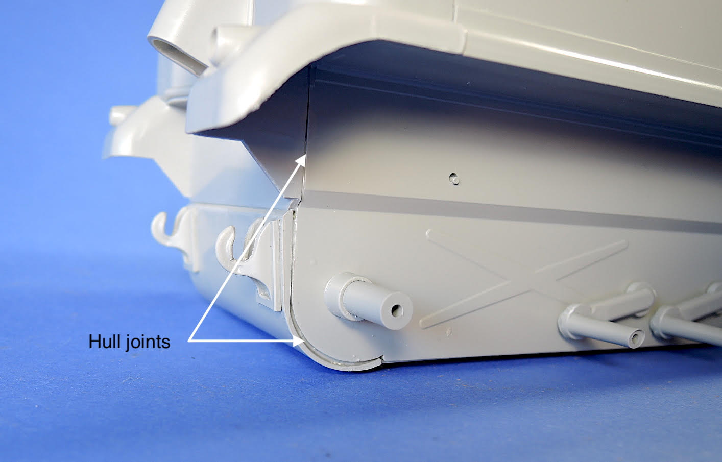
Kettenkraftrad hull joints
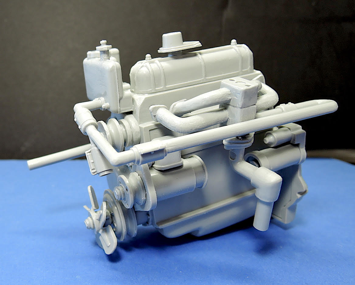
Kettenkraftrad engine assembly

Kettenkraftrad road wheels and tracks
Comments
Add new comment
This site is protected by reCAPTCHA and the Google Privacy Policy and Terms of Service apply.
Similar Reviews