
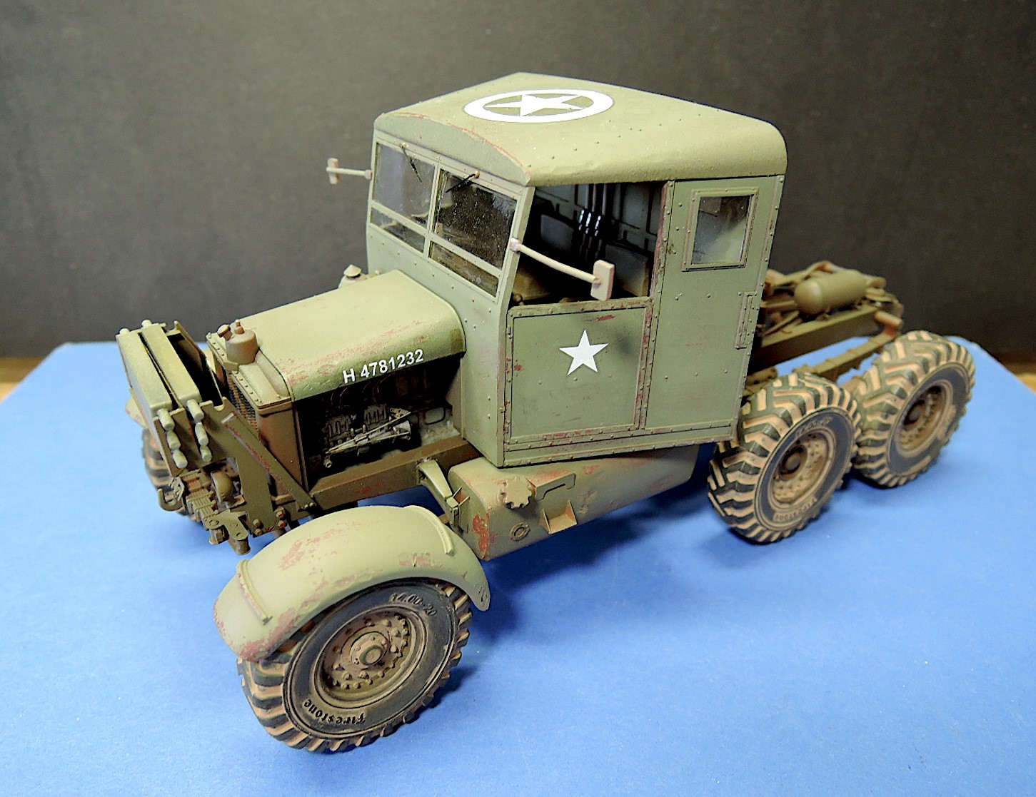
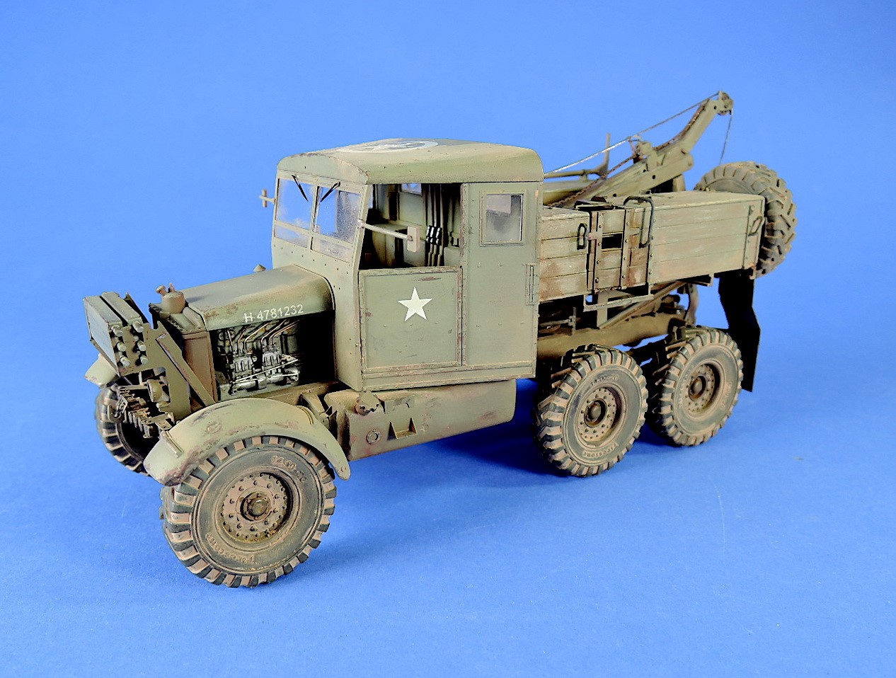
Scammell Pioneer SV2S Heavy Breakdown Tractor
IBG is the first of several manufacturers to issue new versions of the iconic British WWII truck, the Scammell Pioneer. Their first release is the Pioneer SV2S Heavy Breakdown Tractor. IBG has also announced two additional versions of the Scammell, the Pioneer R100 Artillery Tractor and the Pioneer Tank Transporter with TRMU30 Trailer.
Background on the Scammell Pioneer from IBG’s website:
The Scammell Pioneer was a British 6x4 tractor used in the Second World War as recovery vehicle, artillery tractor, and tank transporter. All Pioneers in British Army were equipped with a 102 HP Gardner 6-cylinder diesel engine, rear-wheels drive, and a power winch. Introduced in 1935, the version R100 heavy artillery tractor was used in World War II to tow medium and heavy artillery. 980 Pioneers R100 were produced to the end of the war. From 1936 the British Army began to receive 43 Pioneer heavy recovery vehicles SV1S. Many of these SV1S and R100 vehicles were lost in France in June 1940, destroyed by the withdrawing troops or captured by the Germans. The version SV2S had a redesigned crane with greater lifting height and was introduced in 1938. A total of 1,975 SV2S were built. Delivery of the tank transporter began in 1937. This variant was equipped with a longer chassis for an extended cab to accommodate the tank crew. 459 Scammells in this variant were produced.
The kit comes on 16 gray plastic sprues, one clear plastic sprue, and seven injection molded plastic tires. The kit also includes a 4 ¾ x 2 7/8 photoetch fret with 40 parts, 5 x 3 1/2 in. decal sheet, and a length of very fine thread for the crane cabling. The instructions are an 8 1/8 in. x 12 in. 18-page stapled booklet with 40 assembly steps. The instructions include photos of the sprues, and colors listed for these manufacturers: Vallejo, Hataka, Mr. Hobby and Lifecolor. Colors are called out for the marking options, but there are no detail colors listed in the assembly steps so other references will be necessary. There are several resources online that will be helpful such as Military Modeling Scammell Pioneer SV2S walkaround by Gary Radford, and Capricorn Publications Army Wheels in Detail Scammell Pioneer
Instruction diagrams are small grayscale photos of an actual model and are very difficult to read. The small size and low contrast of the photos make it difficult to see the orientation and attachment points for parts. IBG does include another photo of each completed step which is very helpful during assembly. The instructions also include views of the finished model and colored CAD drawings of five marketing options:
- 1. Scammell Pioneer SV2S captured by German Afrika Korps, North Africa, 1942.
- 2. Scammell Pioneer SV2S from unidentified unit of Red Army, Eastern Front 1943.
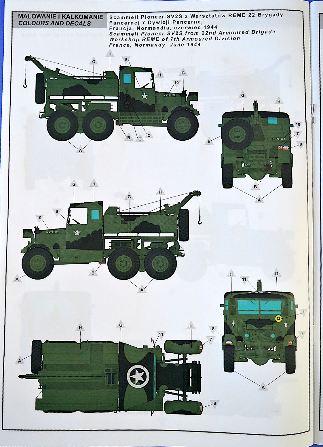
- 3. Scammell Pioneer SV2S from 22nd Armoured Brigade Workshop REME of 7th Armoured Division, France Normandy, June 1944.
- 4. Scammell Pioneer SV2S from 26th Recovery Section of 6th South African Armoured Division, Egypt, January 1944.
- 5. Scammell Pioneer SV2S from 16 Company EME of 1st Polish Armoured Division, England, autumn, 1943.
This kit also includes Eduard’s Scammell Pioneer SV2S photoetch set, which is reviewed separately.
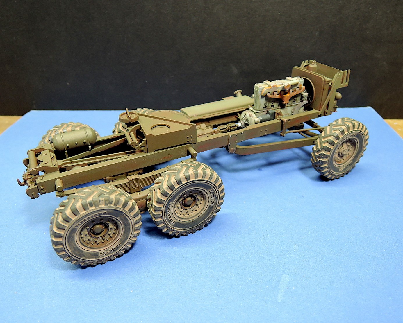
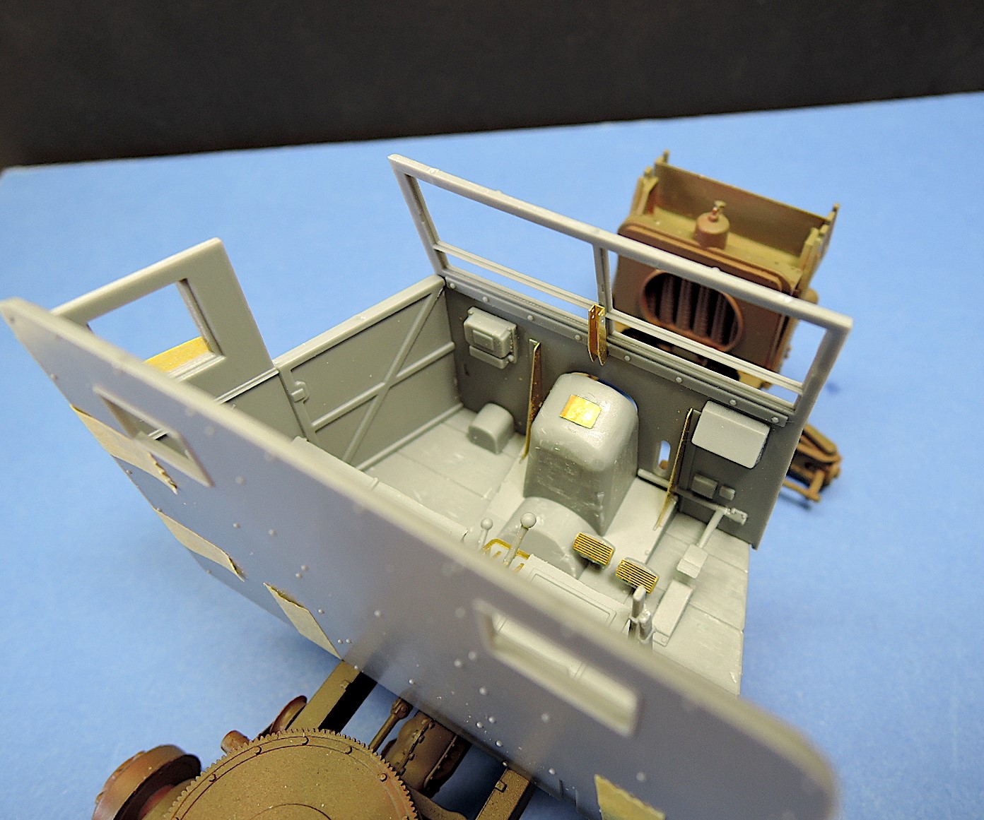
The kit build begins with some of the subassemblies for the chassis: wheels and tires, gas tank, storage rack, engine, and radiator. The tire treads are molded plastic in one piece with a separate piece for the interior and exterior side walls. There is no mold seam, but the joint with the sidewall needs to be sanded down. Note the direction of the tire treads when assembling the tires to get the right number for each tire direction. The gas tank comes in two halves and the joint needs to be filled and sanded to get a smooth joint. Make sure that the top of the gas tank is below the top of the chassis when it is installed so that the cab fits correctly later. The storage rack on the driver side of the vehicle has photoetch for the front grill, bottom, and rear. The straps on the front are incorrect as only the top horizontal extends to the end panels. The other two horizontal bars stop short of the end panels. The Eduard photoetch set has corrected this.
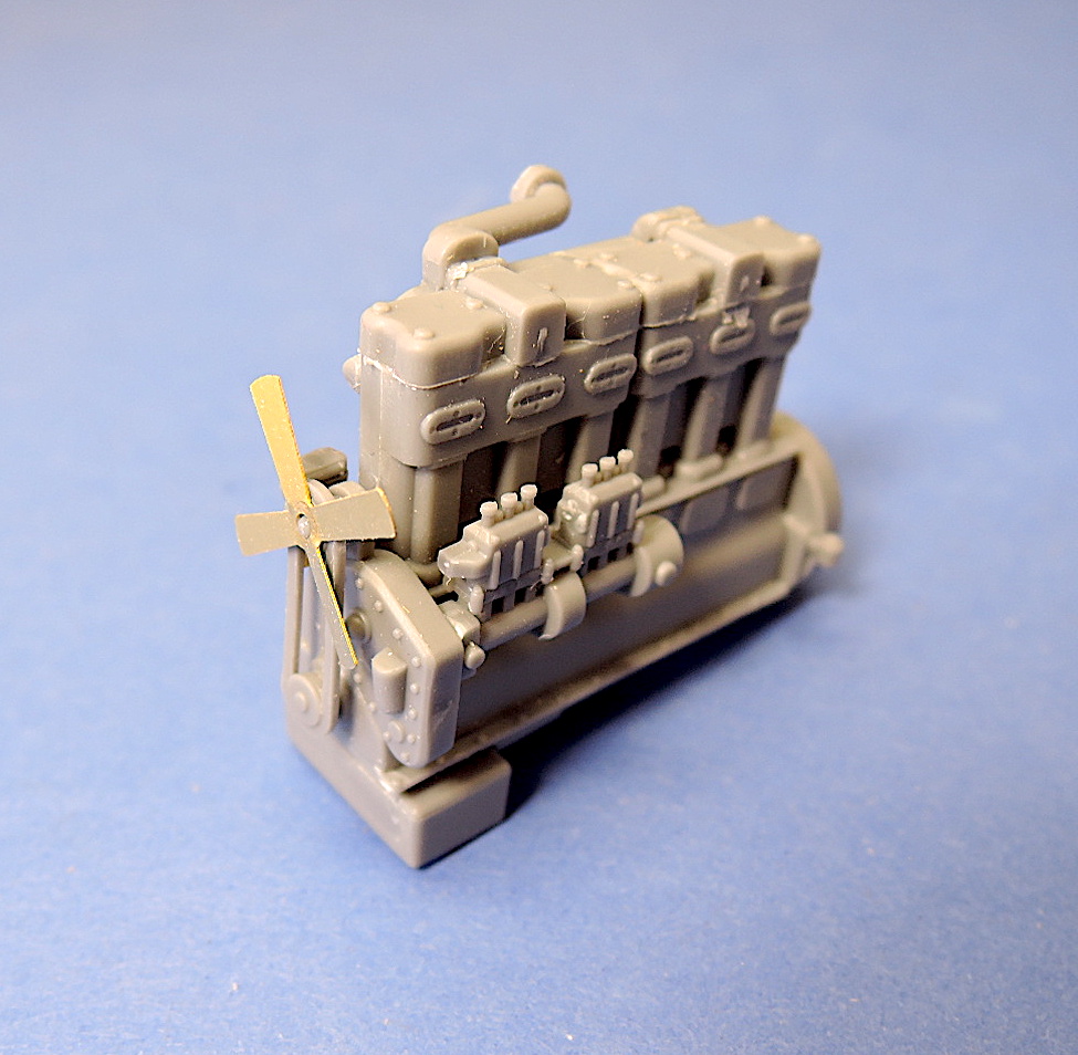
The engine is a nicely detailed assembly of 22 parts. The starter for the engine, H10, should be installed after the bellhousing to get it aligned correctly. The engine lends itself to additional detailing so I added fuel piping and some of the throttle linkage. The hose, part G4, shouldn’t be installed until after the external air filter is added later to get it aligned correctly. The radiator has very nice casting of the core elements, but unfortunately most of it is hard to see in the completed model.
The next series of steps 7 through 11 build the chassis and suspension. Make sure that the rear suspension pieces in step 7 are all flat on one plane so the tires will sit flat when the vehicle is completed. In step number 8 the tie bar, F22, needs to be installed in the frame elements G25 and G26 before they are cemented together.
In step 9 there is an example of the difficulty reading the instruction photos. The cross piece H20 has notches that need to be on facing up and to the rear. This is not at all clear in the assembly diagram. In step number 10 the front crossmember F19 is also not clear. The extended end should be on the left side of the chassis.
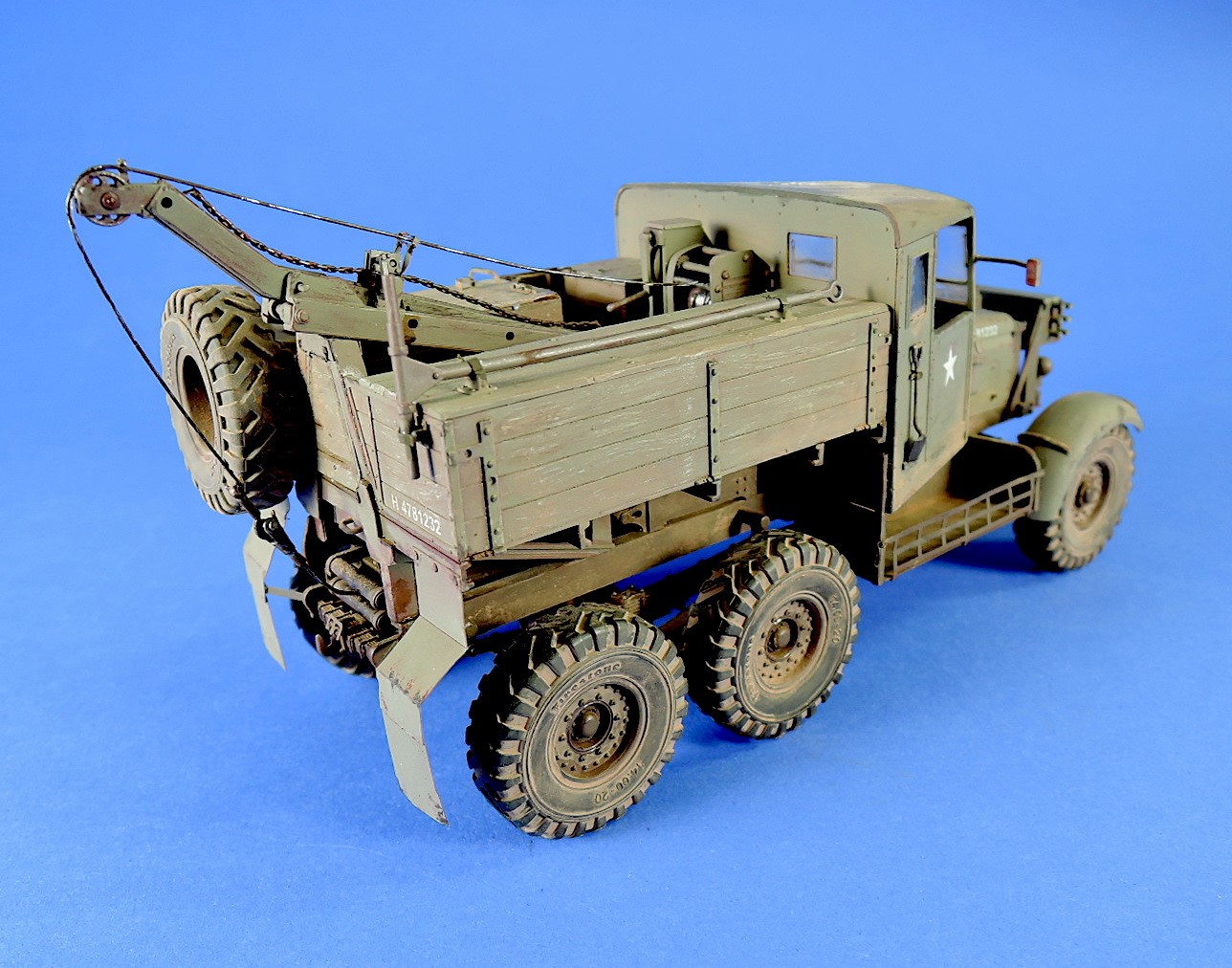
Step number 12 assembles the winch. The bolts on the part D 6 should be on the back or outside of the winch. This would be a good time to install cable if desired. The thread that is supplied with the kit for cabling is way too small and I replaced it with a .6 mm beading wire. Careful gluing of the winch reel will allow it to rotate and wind the cable.
Steps 14 through 17 install the engine, winch, and suspension pieces to the chassis. It would have been easier to install the transmission flywheel pieces to G20 to G22 if they were molded as one piece. This assembly also came up a few millimeters short of the engine when installed in the chassis so I added a piece of styrene rod. When installing the front and rear suspension assemblies in step 16 & 17, make sure they’re all the same plane so the wheels will sit flat on the ground.
Step 18 installs the steering arm and rack for the front counterweights.
Step 19 and 20 build the hand operated winch for the boom. Leaving the cable drum part A6 free to rotate will allow winding the cable drum.
Steps 21 through 23 build the boom for the crane. In step 21, be careful to not cut off the small tabs on the boom of outrigger parts C3 and C4. The outrigger can be slid in and out if desired using the locking pins C13 and C18.
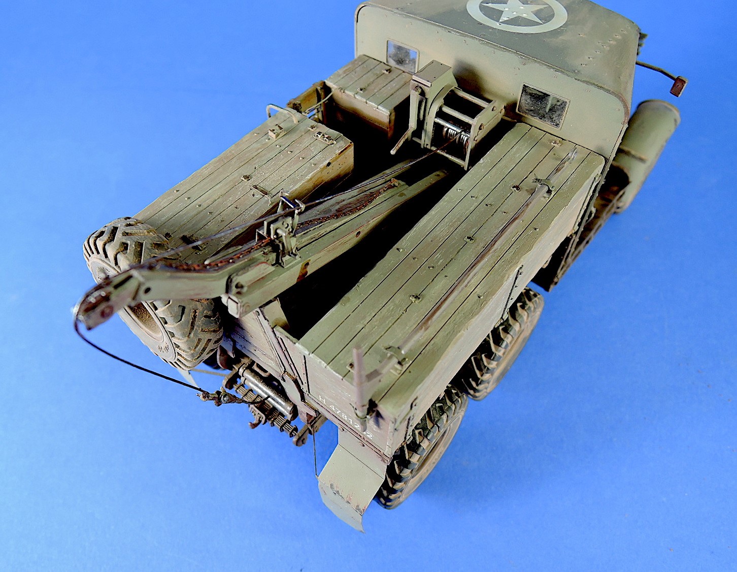
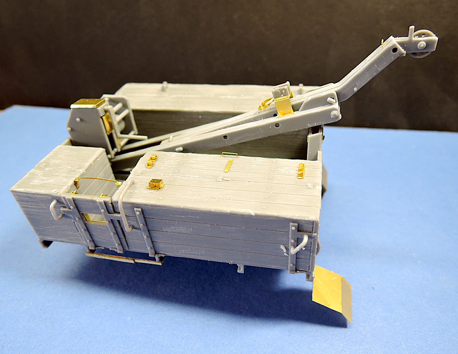
Steps 24 through 30 build the truck bed, install the boom, and build the toolboxes for the rear of the truck. The fit of these parts is excellent and the truck bed goes together well. Unfortunately, the wood pieces for the truck bed do not have woodgrain molded into the boards. I scratched them using a coarse sending stick, cut in the joints at the ends of the boards, and gouged the boards to make them look a little more realistic and worn.
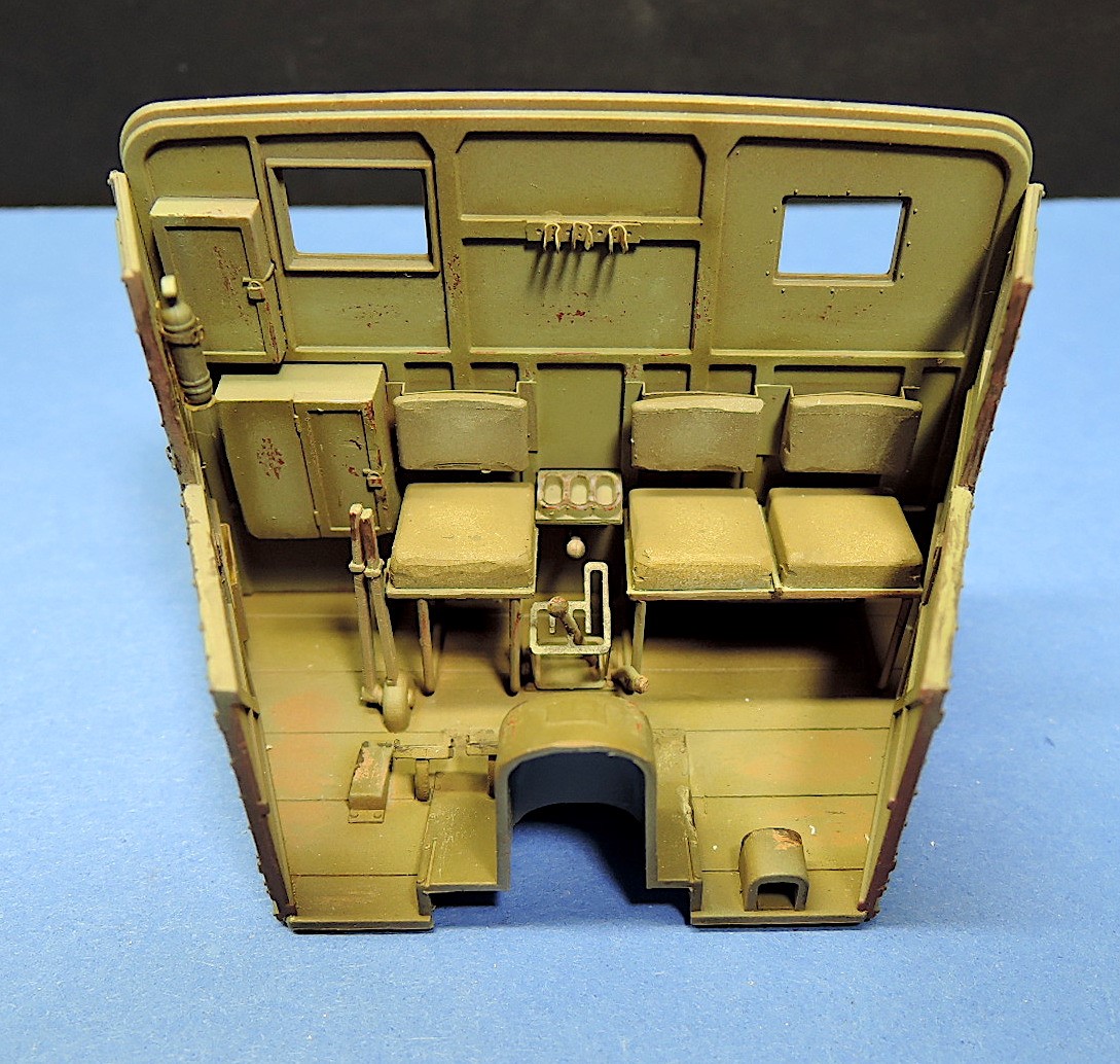
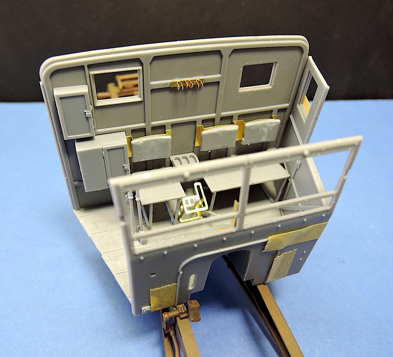
Steps 31 through 38 build and install the cab for the vehicle. The part fit is again excellent and the cab goes together well. There are no decals for the instrument panel. part. A photoetch piece, part PE12, is provided but the gauges need to be painted on. There are also some very small hinges for the out-swinging windows, parts PE41 and PE42. The doors to the cab do not open without cutting apart the sidewalls of the cabin. There is no clear piece provided for the rearview mirrors, so I fabricated one out of some spare clear plastic.
Step 38 installs the bed on the truck, and the wheels are installed in steps 39 and 40. The rear suspension provides a nice solid base for the rear wheels, but the front wheels are a little more flimsy. Also, the front fenders do not have a very substantial mounting, although the struts are probably close to scale thickness. The clear plastic windows fit very well, even after painting the frame areas. The sides of the windshield slope out at the top, which is not correct. The frame sides should be vertical as seen in reference photos.
The last page of the instructions shows photographs of the completed model and is the only indication of the cable routing. Again, the cable provided with the kit is way too thin. The remaining pages of the instruction booklet are the five marking options for the kit.
I painted the kit with Mission Models red oxide primer, olive drab, and faded olive drab acrylic paints, and A-K Interactive dark rust. Mr. Color wood color was used as a base layer on the wood parts under the olive drab paint, which was then chipped with the hairspray method.
The SV2S kit is highly detailed, has excellent part fit, and makes into a nice model. I spent about 30 hours on the kit assembly, and another 16 hours on painting and finishing. The kit includes photoetch parts, and the instructions are difficult to read, so this is a kit better suited for experienced modelers.
Thanks to IBG Models for producing this wonderful kit, and I look forward to building their other versions. Thanks also to the IPMS Review Corps for letting me do this review.


Comments
Add new comment
This site is protected by reCAPTCHA and the Google Privacy Policy and Terms of Service apply.
Similar Reviews