
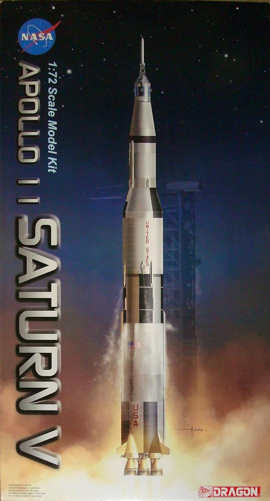
Saturn V Apollo 11
A direct descendant of the German V-2, NASA's Saturn V rocket was – and still is – the most powerful rocket in the world. It was developed over a period of seventeen years, with its final name and design being accepted in 1963.
Apollo 11, the subject of this Dragon kit, was in some peoples’ estimation the greatest achievement of mankind. The mission itself was the fifth in the Apollo program and the second with an all-veteran crew. Neil Armstrong, Michael Collins, and Edwin "Buzz" Aldrin comprised the crew, and Apollo 11’s LEM landed on the moon on July 20th, 1969. The first to step on the moon was Neil Armstrong who said, "That's one small step for man, one giant leap for mankind.. The command module is currently located in the Smithsonian Air and Space Museum.
Today there are three Saturn V’s which survive, one in Huntsville, Alabama, the second at the Kennedy Space Center in Florida, and the third at the Johnson Space Center in Houston, Texas.
This is a very large model, standing 5 feet 1 inch tall and containing about 288 parts. Some of the larger parts came with “flags” molded on them with their appropriate part numbers, but several were broken off. There were two kinds of rocket body parts – the smooth parts, molded in halves, and the corrugated parts, molded in several sections. Parts B-1, the half-circles of the first stage’s smooth section, were warped on my sample, which I minimized somewhat by sanding them out since they were flared at the end, almost like a flange.
There are the starts of mounting holes on the inside of the segments and I was forewarned to drill them out before assembly. In truth, there are hole starts everywhere, and it was difficult to figure out which ones I needed and which ones I didn’t. I believe the holes for the piping, part # B-3, which runs up the side of the first stage, are in the wrong locations. The instructions say to put them in a different position than what’s shown on the four-view drawing.
There were no holes started in the corrugated sections anywhere for parts G-1 and G-8 (sections of the piping going up the first stage), so I just cut off the mounting nubs. From this point on, I quit drilling holes and just cut off the mounting nubs, then glued the pieces flush to the rocket body. Done this way, the modeler can build the rocket and then orient the parts according to the four-view.
Section D-2 (the lower corrugated section of the second stage) was of a larger diameter than the sections above and below it, and had some sink marks in it as well. To get the best fit, I rotated mine 180 degrees…and it made a difference. There was a lot of slop between parts F-1 (the engine mounting platform) and E-4 (the second stage body). I moved part F-4 (the fuel tank top) from the second stage to the top of the first stage. It would not have been seen in the second stage and was needed at the top of the first stage.
Although part G-8 on the third stage is shown to be on the centerline, which is a seam on part B-4, the smooth section, I believe the correct placement is off-center as the four-view drawing shows. Also, the holes on the inside do, in fact, line up with part G-18, the section of piping on that stage.
On the CSM (command/service module), I installed the six arms (parts # B-11) and had to cut off the pads so the capsule would fit tightly on the round section (what would actually be the 4th stage) tightly; if you’re closing up the rocket, you don’t even need to put these in. I thought the instructions were confusing, but there are two different parts # C-8 (lugs on the bottom of this fourth stage) and they’re way different. Leave out the parts beneath the escape tower and on top of the capsule (parts C-12, C-1, B-8, B-6, and B-7) unless you’re going to display it with the launch escape system (LES) off because the capsule top won’t fit well with these pieces inside.
On the Lunar Module (LM) part G-1, the tapered corrugated LM adapter as shown on the instructions, is in reality part F-1. There are two sprues marked D – one with a small nozzle and the other with a large one. Although the box shows a clear LM, it states that the clear LM is not included, but it is. In fact, your only choice is a clear one. The escape system is also molded in clear plastic with a clear cover for the capsule.
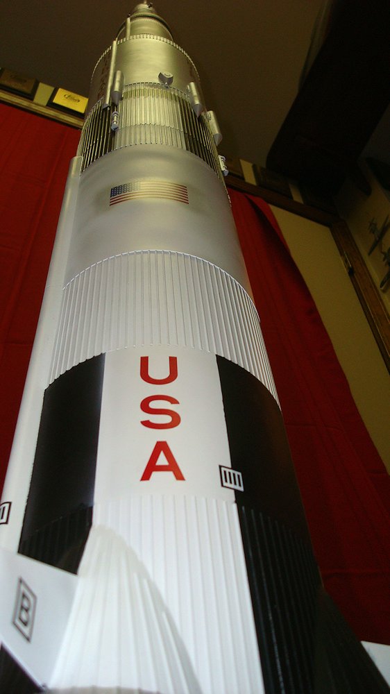
This model took a lot of paint. I used Krylon For Plastic, which worked out okay. Masking was time consuming – I used Tamiya tape and tried to snuggle it down into each corrugation, but I still had some underspray which needed to be touched up. The decals are on-register, and the clear bonding film is very close to the edge, so only a small strip of clear connects the letters in “United States,” etc. This was nice since there was no need to trim any decals.
There were two decals marked #48. The three-striped one is #48 and the four-striped one is #49. I used Micro Set, which worked fine, and if I had a bubble I used some Micro Sol to make the decal conform.
The kit includes a base with an aluminum rod on which to display the rocket. There are extra parts for the LM which makes it look like you could build it with the gear down, but the instructions only show how to build it gear up so it fits inside the rocket. A second small sheet of instructions was included but I couldn't figure out why.
The only English language part of the instructions are the names of the general areas of the rocket, i.e., first stage, lunar module, etc., and having the various other parts named would’ve helped. Although this kit builds into an impressive-size rocket. I found it a tough build.
Thanks to Dragon Models USA and IPMS/USA for the review opportunity.
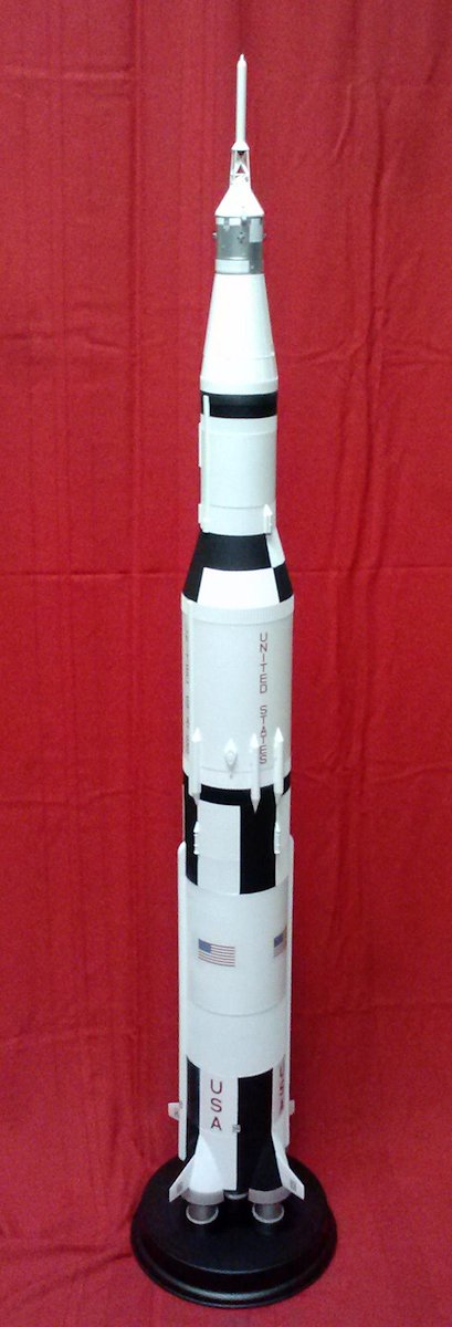
Completed model
Completed model from base
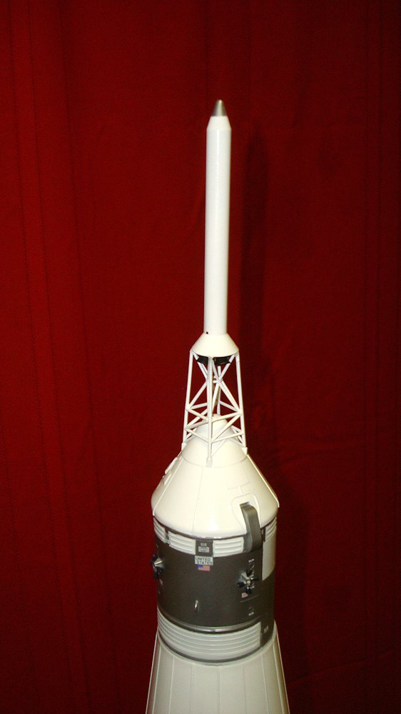
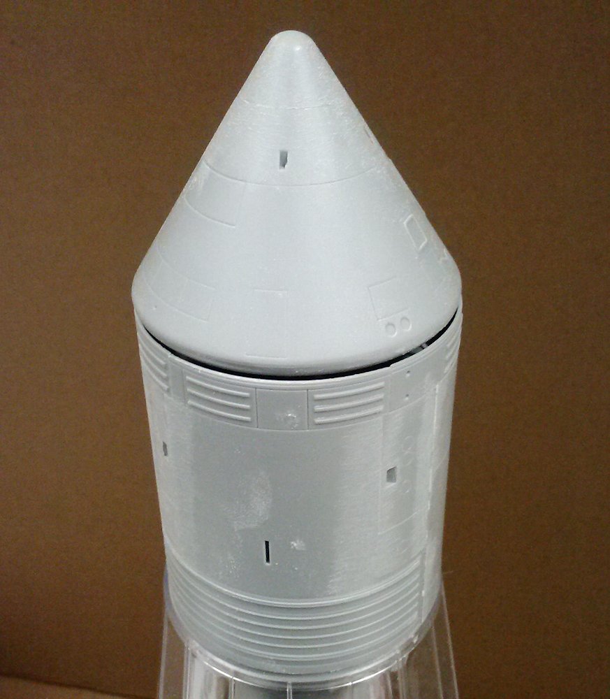
Command module with escape tower
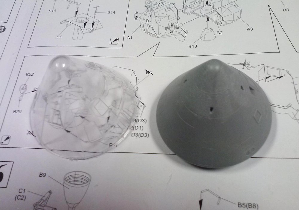
Command module with launch shield

Command module inside launch shield
Command module pads, which were too tall
Gap if pads were not cut down
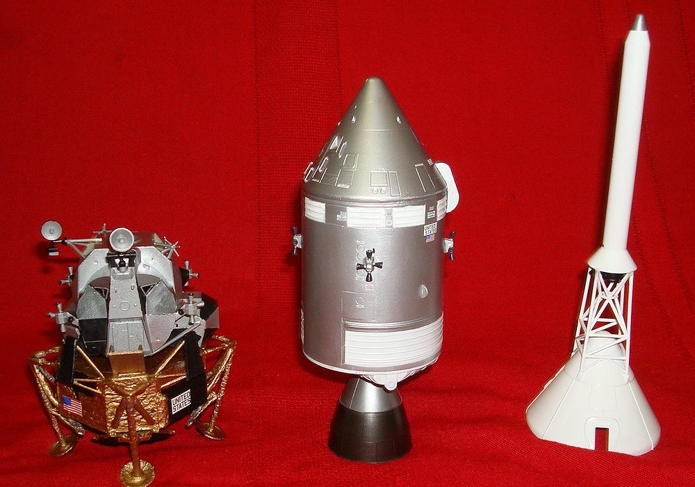
LM, CM, and escape tower
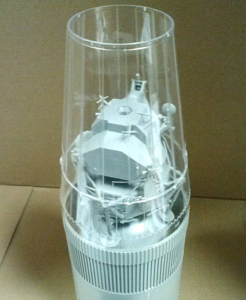
LM seen through clear section
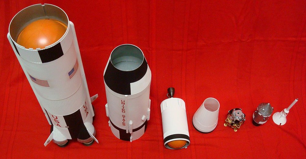
Rocket sections

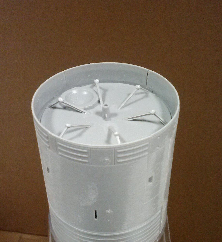
First, second, third stage engines
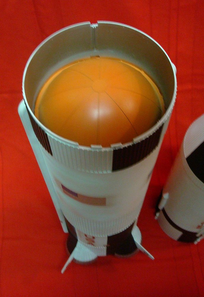
First stage fuel tank top

Comments
Add new comment
This site is protected by reCAPTCHA and the Google Privacy Policy and Terms of Service apply.
Similar Reviews