
Russian Heavy Tank KV-85
The KV-85 was an interim tank solution to field a heavier gun than the 76mm mounted on the existing KV-1 series. By 1943 the 76mm gun was no longer effective at long range against Germany’s newest tanks like the Tiger 1 and Panther. The solution was to mount the 85mm D-5T in a new larger cast turret. Only 148 were made until production of the new IS series was brought up to capacity.
Bronco’s kit comes in a larger-than-normal sturdy cardboard box packed with sprues, an eighteen page instruction booklet, a small sheet of brass PE, braided copper wire, and a generous decal sheet. The instructions are well laid out line drawings which are not too cluttered given how many small parts there are in the kit. The PE mostly covers the air intakes and exhaust screens. There is an option for solid plastic intake screens but the exhaust screen is only offered as brass.
The plastic parts are nicely molded with overall fine details. The turret halves and front have simulated-cast texture. Fine weld beads are present on the upper hull. There are some very small and very thin parts in this kit. A sharp knife and tweezers are going to be necessary tools. This is a highly detailed model, not a shake and bake kit.
The kit includes individual track links and pins that will remain workable with careful gluing and handling. The tracks and pins need to be trimmed from sprues, which might get tedious for some, but a handy fixture is provided to make holding the tracks and installing the pins easier.
Four marking options are provided; three solid green with basic turret numbers, and a fourth shown as captured and put into service with the German Army with a whitewash finish. Paint numbers are called out in the front of the instructions for Mr. Hobby, Hobby Color, Humbrol and Tamiya paints. I can’t comment on the first three, but I know that Tamiya XF-62 Olive Drab is not a close match for Russian 4BO Green.
A nice bonus is a glossy print of the box art suitable for mounting on the hobby room wall.
I am not an expert on Russian armor. I cannot personally attest to the dimensional accuracy of Bronco’s kit but it looks like a KV-85. I have checked parts against 3 different sets of drawings, but each drawing differs from the next and it’s hard to know which one is right. One thing I did notice while examining reference photos of the KV-85 on display in St. Petersburg are the weld beads around the engine deck plates, or lack of actually. The KV series engine plates were bolted on. Bronco’s kit has nice bolt detail around the engine plates, but also has delicate weld beads around the edges which are incorrect. This seems a relatively easy fix and I will try to address this in my build.
Steps 1-4
Construction begins with assembly of parts to the lower hull pan. This includes mounts for the torsion bars and the driver's station. A lot of time is spent on tiny little parts forward of the driver’s station, but none of this detail will be visible even with the vision block armored cover raised. Take care when installing parts Gb3 and Gb4 - which should be Cb3 and Cb4. They look nearly identical but the slots are different and affect how the torsion bars orient.
Construction continues in Step 2 with assembly of small details to the lower hull like the bump stops and mud scraper. Steps 3 and 4 install the driver’s station: seat, controls, etc. The parts are very small and need careful trimming. Unless there is something I am missing, these parts are not visible when the model is finished so it is up to you to decide if you want to deal with these.
Steps 5-8
The next four steps cover the road wheels, idler wheels, return rollers and drive wheel. Plus some more invisible details for the nose of the driver’s station. The rear drive wheels assembled with no issues. I pre-assembled the two drive wheel halves first and let dry. By carefully gluing part Gb16 to Gb1, the wheel freely rotates. Also, by carefully gluing the torsion bars and swings arms, the suspension is fully workable too.
In Step 6 there is an option for armored covers for the road wheel swing arms. Part E2 is the correct choice but no orientation features are provided. The correct orientation is for one of the bolts to be axially oriented with the swing arm and facing away from the road wheel. Check the links provided for ref images.
The assembly of the idler, return rollers, and road wheels is a little unique. There is a pin Gb15, Cb1 and Cb7 respectively, that is inserted through the inner wheel and glued to the mount. If the pins and wheels are glued together first, the pin may push back into the wheel assembly and it will be difficult to mount to the swing arm. I found it easiest to apply a small amount of thicker slow-setting liquid cement in the receiving portion, insert the pin through the inner wheel, and allow this to dry. If a little extra glue gets on the axle, gently turn the wheel occasionally while the glue sets and it should remain free to rotate. This can be said for all the wheels. By carefully gluing the pins into the sockets, the idler, return rollers, and road wheels are all free to rotate. I pre-painted the inner wheel halves with Tamiya NATO Black since these areas are going to be difficult to paint later on.
The PE screen for the air exhaust is installed in Step 8. There are a couple of issues with the PE screen. First, it is too long to fit properly in the opening but too short to rest outside the opening. I trimmed about .6mm off one side but this destroys part of the frame which I replaced with styrene strip. Second, there is nothing for the PE screen to glue too except for the thin edge of brass. I knew this wasn’t going to work well, so I glued thin strips of styrene to the inner hull sides and rear plate. This gives a perimeter for the brass to be glued.
Step 9
Step 9 builds a nearly complete engine as seen through the open engine hatch. The detail that is present is very nice, the only thing missing are the wires. The engine compartment misses a few things though. First, there is no forward firewall or additional rear details for the transmission. An empty interior will be visible past the engine on either side. Bronco also missed an opportunity to provide details for the air intake vents when the optional brass screens are used. No detail is provided here.
Step 10
Step 10 starts off assembly procedures for the engine deck, but before any parts were glued on I needed to deal with two issues of the single top hull plate A22. The first issue is the overall length. The kit part appeared a little short. When I lined up the front features, the rear edge was too short. When I lined up the rear edge the front half would not seat properly. I cut the part in half at the forward most weld line (which should only a clean panel edge). I cleaned up the rear half and glued a strip of 0.010” sheet styrene to the newly cut edge. This extra spacing allows the parts to sit correctly. I also glued a strip of styrene to the rear half so the front half would have something to glue to.
The other thing I dealt with at this time with was the above-mentioned issue of the engine deck weld features that should not be there. I shaved off any raised welds and scribed in the correct panel edges. Careful sanding and scraping is needed to avoid destroying the bolt heads. The upper edges of the side hull plates were not flame cut as depicted; they were machined smooth edges. Rather than fill and sand this flush, I glued 0.005” styrene strip over the flame cut edge and blended this in with the side plates.
Step 10 also installs the engine and transmission vents. The engine hatch is labeled as “Open” or “Closed”. Hopefully that choice was made sooner rather than later if you built the engine. Step 10 also has an option for open or closed transmission vent covers. No transmission is provided so it’s best to glue these shut. If you choose to glue them shut, use the locking features molded on the underside to orient the parts properly. The flat edge should face forward.
Steps 11-12
Step 11 offers the option of molded solid intake vent screens or photo etch screens over a plastic frame. The screens are a bit complex comprising 5 parts each. One for the screen, which is some of the finest PE screen I’ve seen, and two pieces each for the top and bottom frames. I found the screen to be too small. It only just fit within the frames and wasn’t properly sandwiched so just sorta rested there. I assembled one side for the review but gave up on the other. A one piece screen/frame combo would have been more than adequate for a kit-supplied PE part. I eventually opted for the solid plastic screens because even if I got the PE version assembled there isn’t any detail under the screens. The louvers will need to be scratch built or sourced from an aftermarket PE set.
Step 11 also adds the horn and lights to the front hull. The conduit for the wires D9 went flying out my tweezers never to be seen again. I made a replacement with styrene rod and added the missing wires with very fine copper wire.
Step 12 adds small details like the fuel caps and lifting points. It also adds additional interior details to the roof of the driver’s station. The PE rain shield above the visor is not a production feature and can be omitted.
Steps 14 and 15 assemble the left and right fenders. The steps have you glue everything to the fenders, brackets and armored cheeks and then glue this to the hull. I knew there would be alignment issues with this later on so I skipped a step and glued the upper and lower hulls together first. I then glued the hull bulges D22 and D23. The seam along the sides had to be cleaned up first with putty and a bit of primer. When this was cleaned up, I glued the fenders to the hull. There are no location tabs on the hull sides so it will be easy to glue the fenders on out of alignment. I would recommend drawing a pencil line based off the bottom of the hull bulges. After the fenders were glued to the hull, I glued on the support brackets making sure they mated with the hull properly.
Step 16 assembles the tracks. The individual track links are nicely done. An “A” and “B” link (with guide tooth, without guide tooth) are joined with two small pins. There are two part numbers for the pins Cdi and Cdo. I’m assuming these are for Inner and Outer. The head of the pin faces the hull. Lots of trimming is involved but the parts clean up nicely. I tried a few times to get into a rhythm with assembling the tracks and eventually decided that it was easiest to trim everything off the sprues first, clean them up, and then worry about assembly. It was tedious, but assembly felt quicker.
The pins are sized smaller than the hole in the track, so they will need to be glued to the outer face. Normal liquid cement is a little too thin, and capillary-action will draw the glue in and fuse the links together. I finally settled on using thicker liquid cement, and brushed a small amount onto the outer hole and then pushed in the pin. Sometimes a little got onto the next link so I kept working the joint while the glue dried and the links remained fully functional. Once assembled the links are robust and held up well to painting with Tamiya acrylics.
Step 17 assembles the spare fuel tanks. Bronco was very clever with parts breakdown. The ends glue to a central tube and a long seam to clean up is avoided. The strap detail on C1 and C2 was a little soft so I scribed the edge to add definition.
Step 17 also assembles the grab handles to the rear engine deck. These are very thin parts, so a lot of care should be taken trimming them from the sprue. I cleaned as much of the small seam lines as possible before trimming. Thinking clippers might crack the parts, I made light cuts with an X-acto blade until the parts were free. The sprue remnants were cleaned up with files and sanding sticks. The attachment points for these parts are very small; just tiny little ends. To attach the rails I used faster-setting liquid cement to first glue the end points then glued the center points. The rails are surprisingly robust and have done a good job of staying in place.
Steps 18-25
The last portion of the instructions covers the main gun assembly and turret. The main gun is very well detailed down to an individual pinion gear for the gun elevation. A nice bit of detail is also added to the inner roof of the turret including the periscopes and rear MG. The periscopes even have little PE bolts added, but these parts sit so far forward that none of this will be visible even with the hatches open, but its nice to know it’s in there.
The gun elevation gears can actually mesh and allow the gun to freely move but there is a small fit issue. There is a little pin B10 that secures the pinion D4 to the elevation frame B22, but the hole in the gear is too small and will need to be drilled out. I chose another route. I glued the gear in place, sliced off enough of the teeth to allow the gun to still move freely but left enough engagement that the barrel elevation stays in place.
The details provided in the turret are very well done, but there is still a bit missing if you want to show the hatches open. The commander’s hatch has a complete hatch periscope assembly and vision blocks with little PE handles. The commander’s cupola A23 is a delicately molded part. Drawings indicate this has an armor thickness up to 82mm thick. The kit part is too thin to replicate this and will need to be built up if you choose to show the hatches open. Or stuff in a figure and you should be OK. Or, even easier, glue the hatches closed.
The vertical seams formed when the copula is mated to the turret roof should be eliminated, but be careful not to accidentally fill in the vision slits. The slits should have rounded ends. I used epoxy putty to both fill the seams and add the rounded features to the slits. I also used epoxy putty to add the weld around the commander’s cupola and armored vent cover Ga3. The KV-85 turret has two armored plugs as machine gun ports, one on each side. These are just lumps on the side on the kit with no detail line. I used a circle template to scribe the reveal line to better define the plug.
The kit turret halves B34-B44 and cheeks B33 have a nice simulated-cast texture but is a little consistent. I used Mr Surfacer 500 jabbed on with an old brush to enhance the texture. When dry, I smoothed it out with fine sandpaper. The interesting horizontal marks on the sides match those of the one on display in St. Petersburg, Russia, but I am not sure if these are unique to one vehicle or present on all KV-85 turrets. The casting numbers also match those on the display piece.
The KV-85 cast turret has a prominent rough edge where the mold halves met. On the real turret there is a bit of flash left from the casting process and this was ground off. On the model this feature partially falls where the turret top and bottom meet so the seam should be easy to clean up. The portion on the forward section was a little soft compared to photos so I glued a piece of stretched sprue, softened it with liquid cement and sculpted the rough features.
The kit mantlet B43 and commander’s cupola A23 should have a fine cast texture. I used Mr Surfacer 500 jabbed with an old brush to replicate this.
Step 24 assembles the turret halves and the main gun D11. The barrel is molded as one piece. There is some misalignment in the mold and this results in a seam that needs to be cleaned up. It also results in an out of round lip at the business end of the barrel. I had to file and sand and shape and build up this feature with putty to reclaim the profile. A better solution would be a turned aluminum replacement.
Step 25 attaches the turret details. The lifting hooks C6 should have a prominent weld all around. I replicated this with epoxy putty. Part B8 doesn’t match any reference photos.
Steps 26-27
The last steps assemble the turret, fender brackets and nose armor. The turret has a nice fine tooth interlock that keeps the turret seated properly and prevents it from falling off. Be careful with this, as too many on/offs of the turret will snap the little tabs. The final assembly step #27 assembles the tow cables. The instructions are a little confusing here. It shows two different cable ends being installed on both the front and the rear. The rear illustration looks like a holdover from the Bronco SU-152 kit. The correct part is Ga13 and this should be used on all fours ends. The supplied copper wire is very pliable and conforms nicely.
Paint
After primer, I airbrushed the model with Tamiya NATO Black to pre-shade the recesses and undersides of the model. The main body was painted with a custom mix of Tamiya Acrylic colors. The tracks were painted in two steps. First the ground contact face was airbrushed with earth tones - Buff, Deck Tan, Flat Earth - in a mottled pattern for variety. The inside face was airbrushed with a dark brown/gray color to simulate the base metal color. This same color was dry-brushed on the ground contact face. The result is the prior earth tones look like ground in dust and dirt.
I dry-brushed the wheel rims with Vallejo Model Color Natural Steel to simulate bare metal. The model was then given a couple of light coats of Tamiya Satin thinned with their lacquer thinner. To help the decals settle down and avoid silvering, I brushed on a coat of Future for a smooth glossy surface. The decals settled down nicely with the use of the Micro Set/Micro Sol combination. I chose to mimic the first marking option since the red star was the only bit of color on the model. I used the individual numbers since I wasn’t trying to replicate a particular vehicle. When the decals had set overnight, I airbrushed a light coat of the base color to tone down the contrast.
Rather than slather the model with a bunch of dust and weathering that obscures the details, I’ve decided to leave this review sample clean to better show off the kit details.
Overall this was a very interesting subject to build. This is my first Bronco armor kit. I am very impressed with the quality of the molded parts, high level of detail, overall good fit and clear instructions. I was a little disappointed the PE intake screens didn’t work out better but the plastic ones are very nice and can look good with a dark wash.
Thanks to Dragon Models USA and IPMS/USA for the review sample.
Useful Links
- KV-85 Walk Arounds (https://legion-afv.narod.ru/)
- Note: This display piece has had numerous post war patches and modifications but is the best walk around available. Possible KV-1S-85 early prototype.
- https://www.net-maquettes.com/pictures/kv-85-obekt-239/
Historical Images

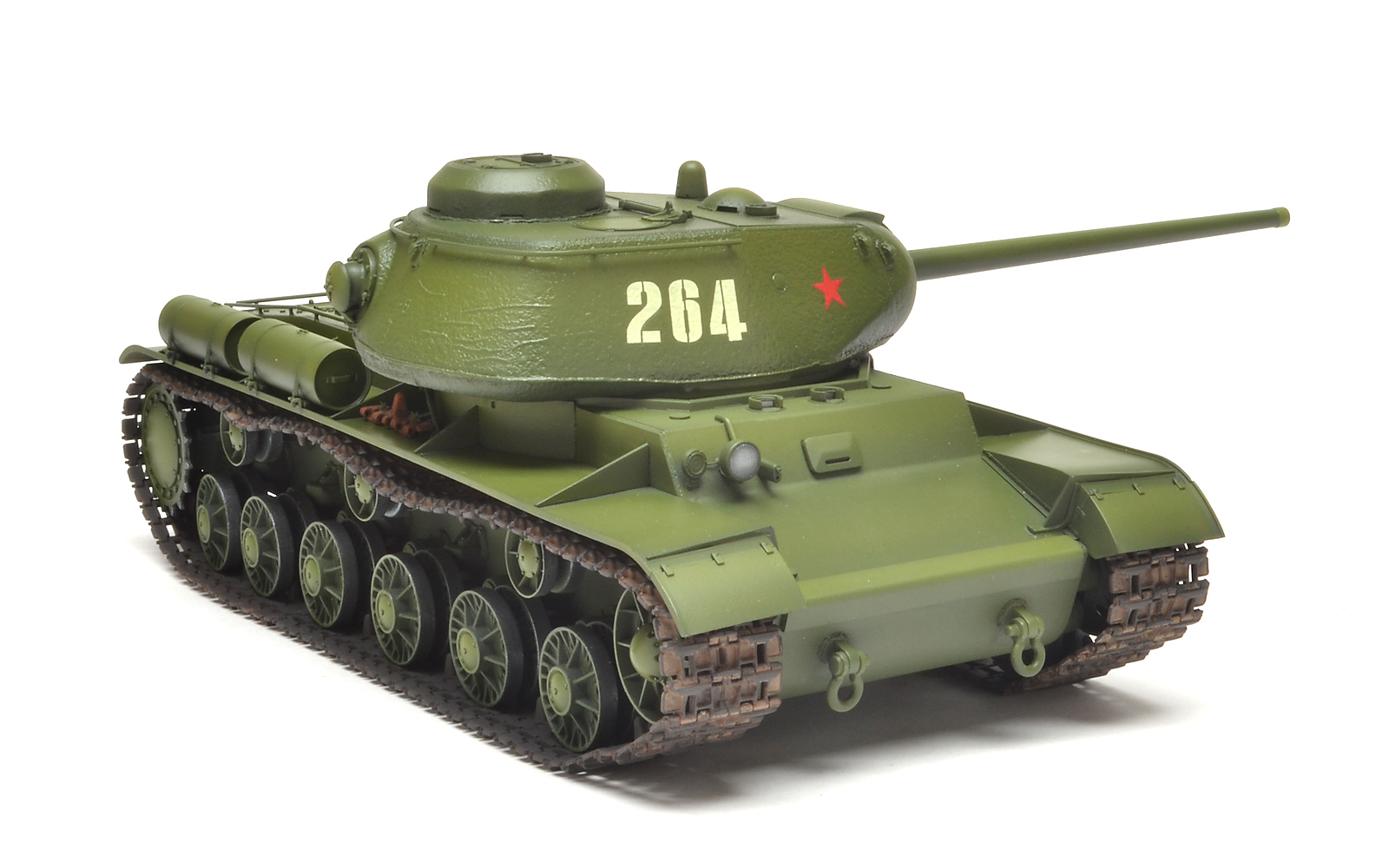
View from right-front - ground-level.
View from right-rear.
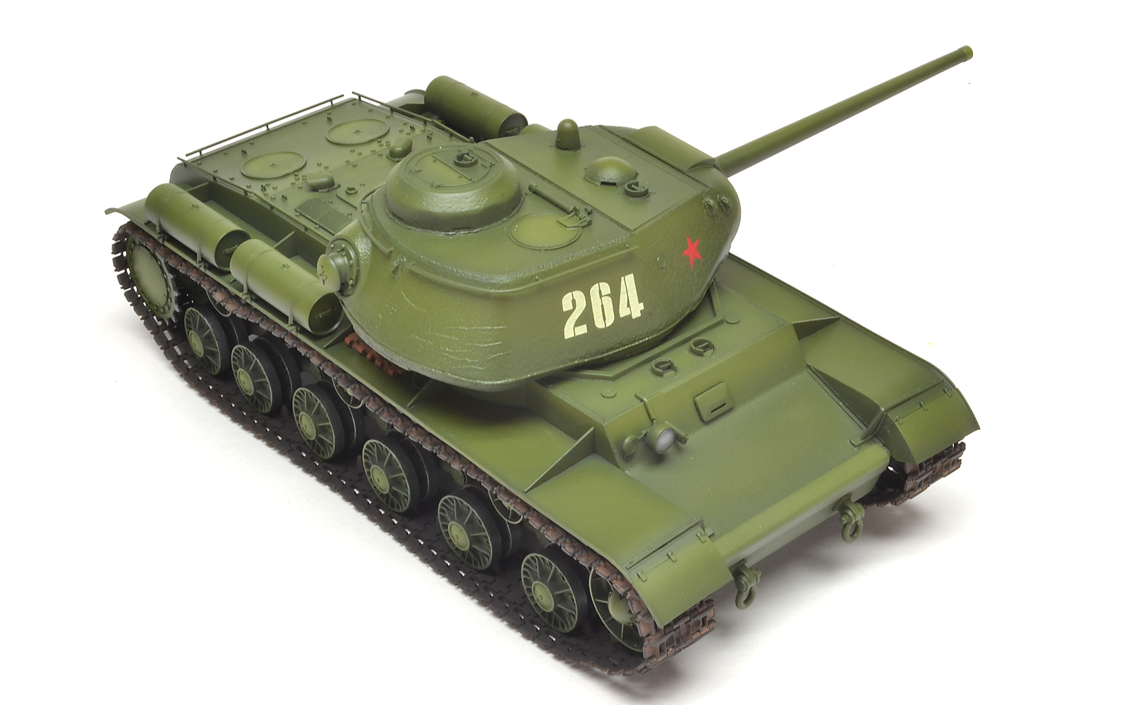
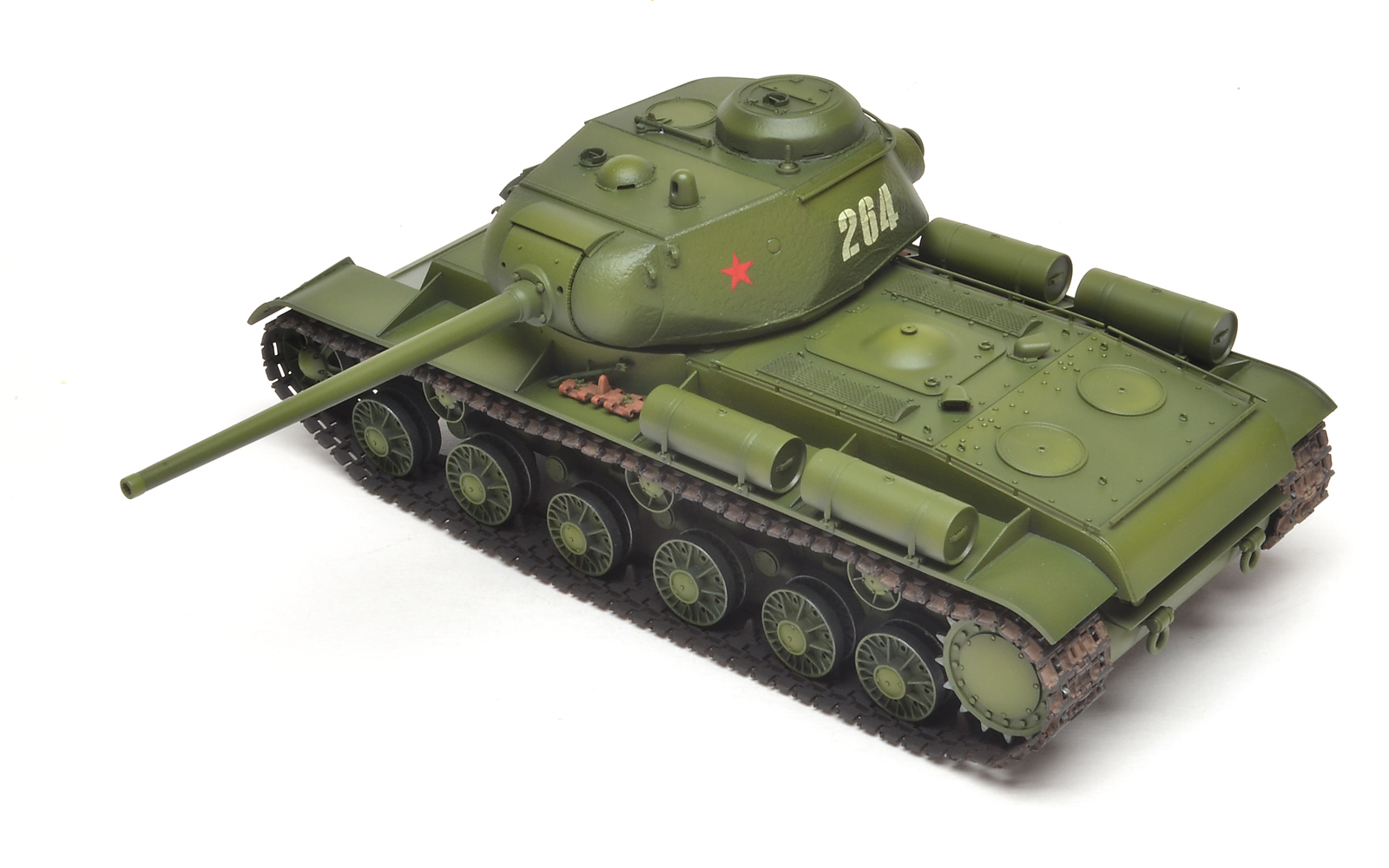
View from above right-front.
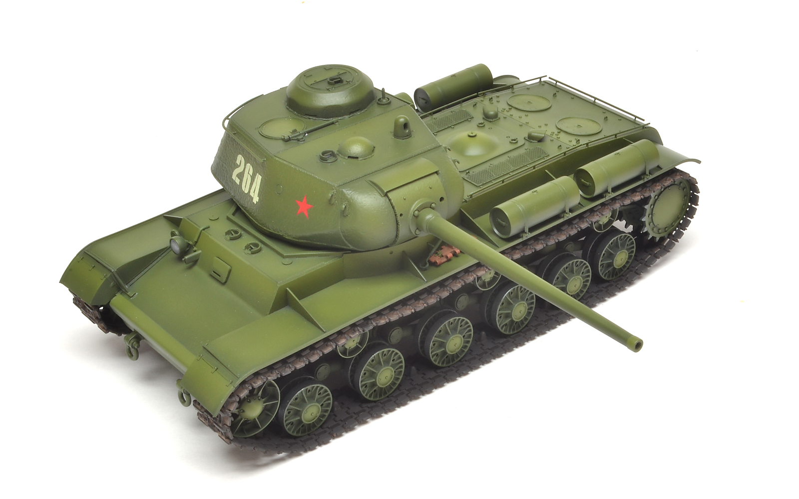
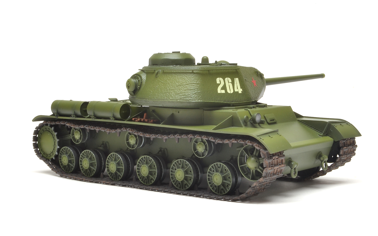
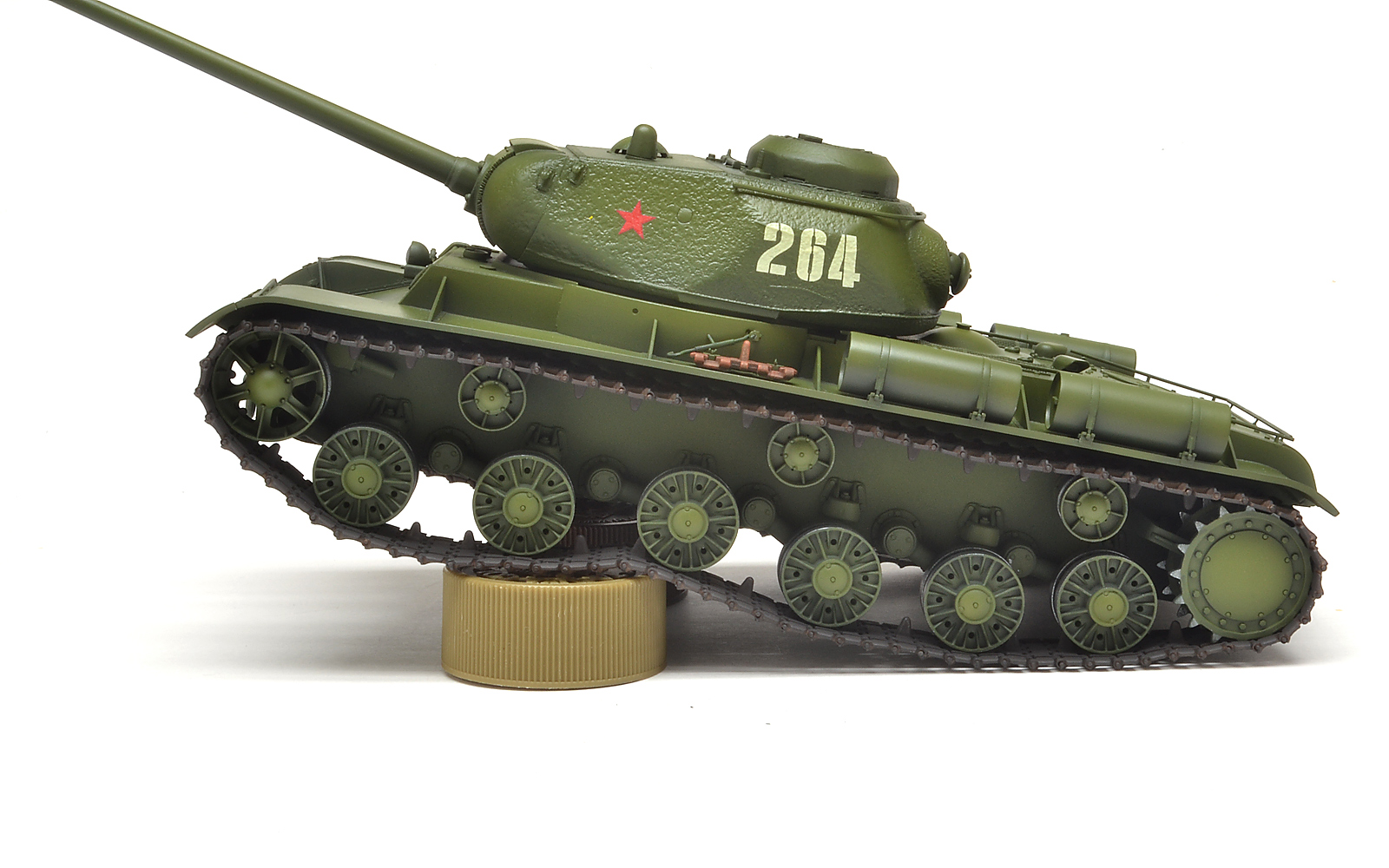
Closeup of left side showing the large cannon and nice turret detail.
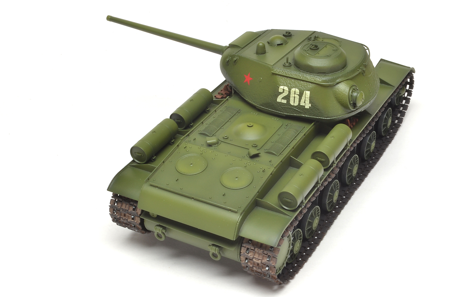
From left-rear, this shot shows the fine weld lines and the deck detail, including screens, and no-seam spare fuel tanks.
Left side ground-view shot showing tracks with realistic sag.
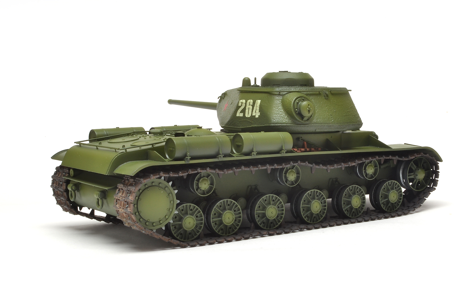
Photo of rear of turret showing the nicely-applied stippling adding surface detail, and the find weld lines.
Another view of the rear of the turret, showing the simulated-cast texture.
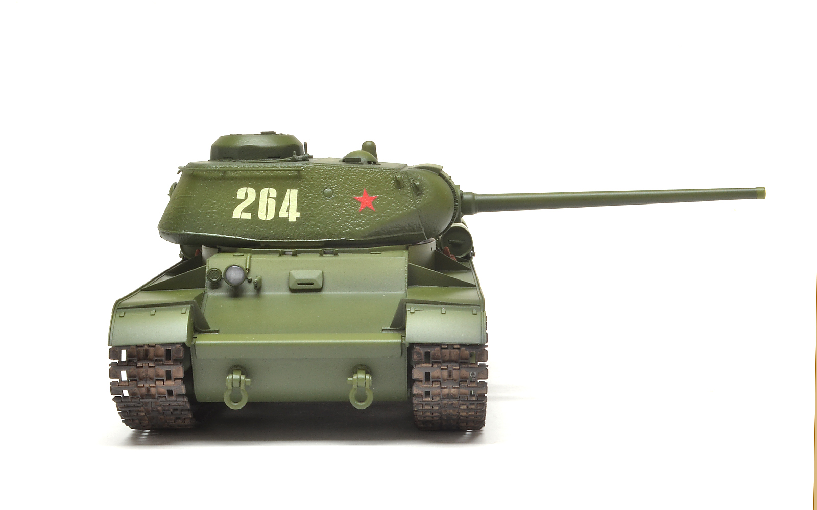
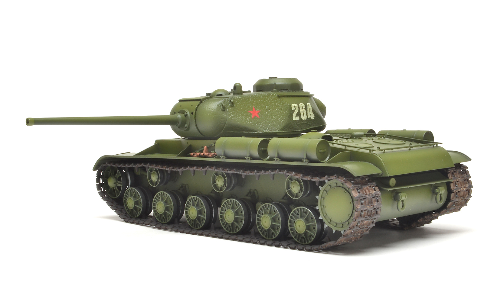
Head-on photo.
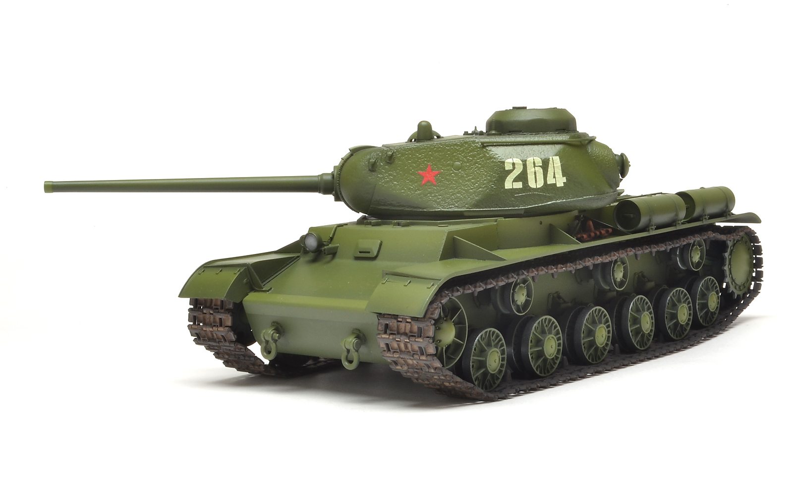
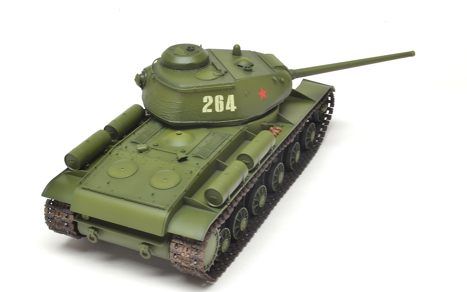
Photo from front-left.
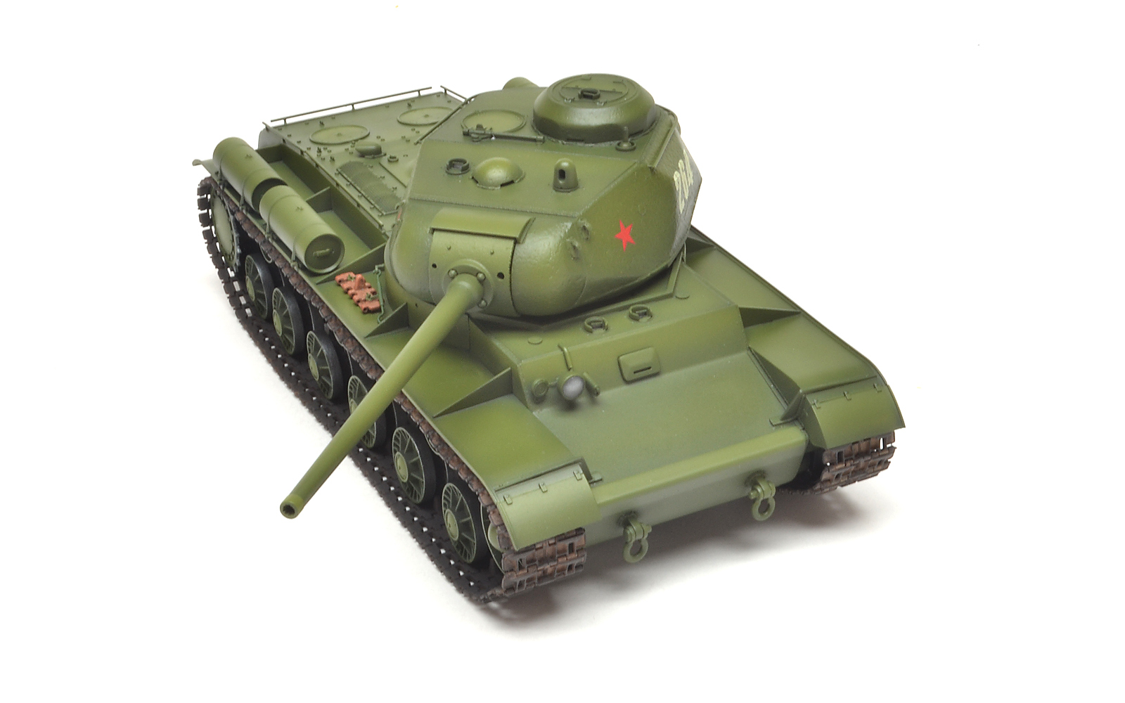
From right-rear above, highlighting grab-rails.
Close-up of barrel and front of turret.
Comments
Add new comment
This site is protected by reCAPTCHA and the Google Privacy Policy and Terms of Service apply.
Similar Reviews