
Rommel’s Mammoth DAK AEC Armored Command Vehicle
Summary
Following the release of the AEC Armoured Command Vehicle Dorchester ACV, AFV Club has “converted” the model to those captured by the German’s in North Africa in 1941. My guess is this is essentially the same kit, but with the addition of resin German radios and different decals. This thought is supported by the fact that the sprue for the exterior tools also has British radios and weapons on it.
The model is extremely well detailed, but requires an extra effort when handling due to scale thin parts that are easily broken. The parts layout and build sequence is simple and straight forward.
Background (Excerpted from the AFV Club description.)
Before the outbreak of WWII, the British Army was planning a wheeled armored vehicle to provide the armored troop commander and staff an appropriate command post.
Associated Equipment Company (AEC), best known for their London double deck buses, was awarded a contract in April 1941 to produce a Matador 4x4 artillery tractor and an armored command vehicle with a Matador 4x4 chassis. By 1941, AEC devoted itself exclusively to military needs. The armored command vehicle entered mass production in XXX 1941. With armor up to 12 mm thick and a weight of 12.2 tons, the vehicle was able to accommodate 7 to 8 personnel. Both High Power and Low Power versions were built. The “Power” refers to the signal strength of the radio equipment. A total of 415 were produced. Due to the very comfortable ride and interior the troops nicknamed the vehicle Dorchester after the luxury hotel in London.
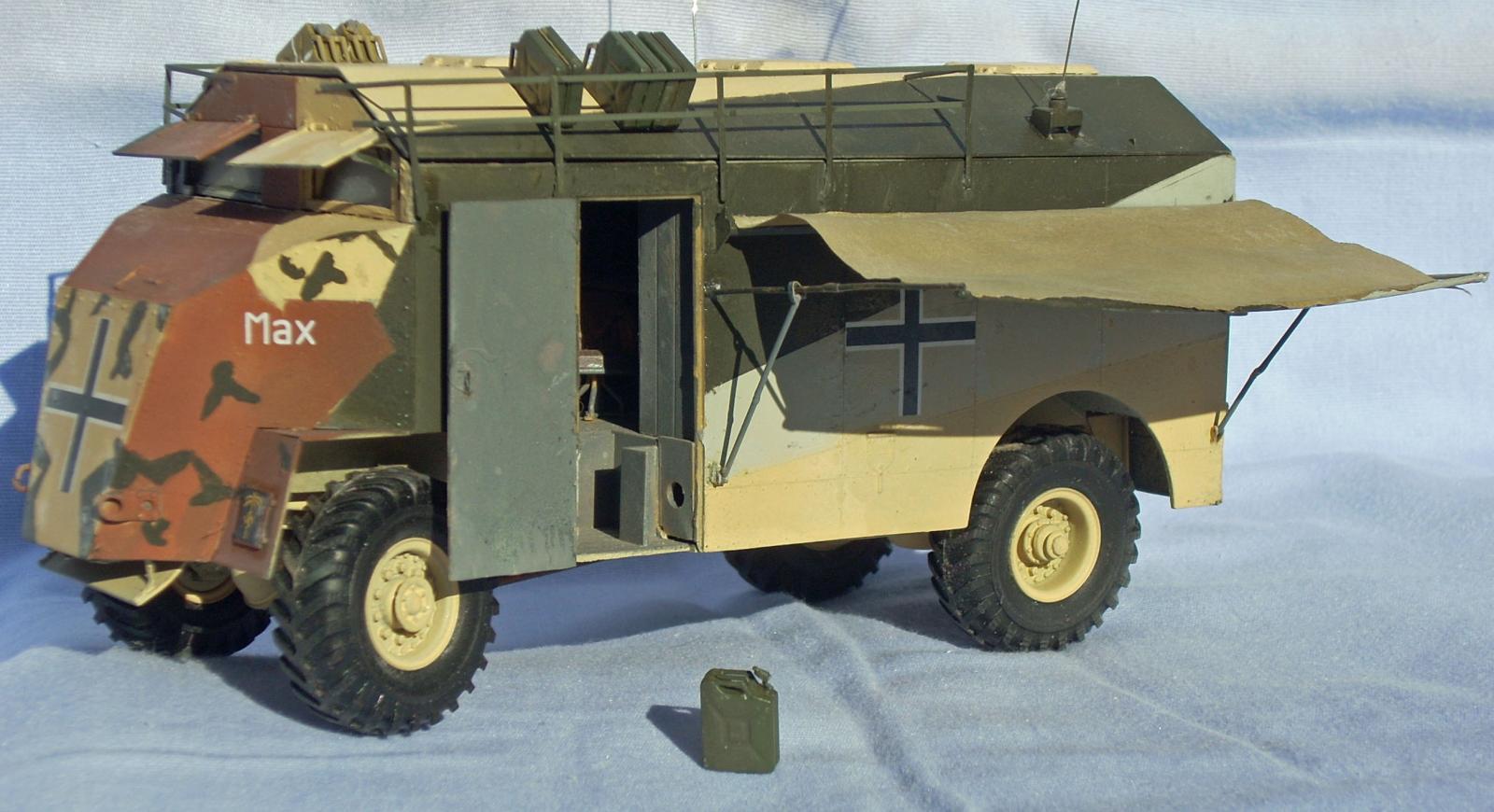
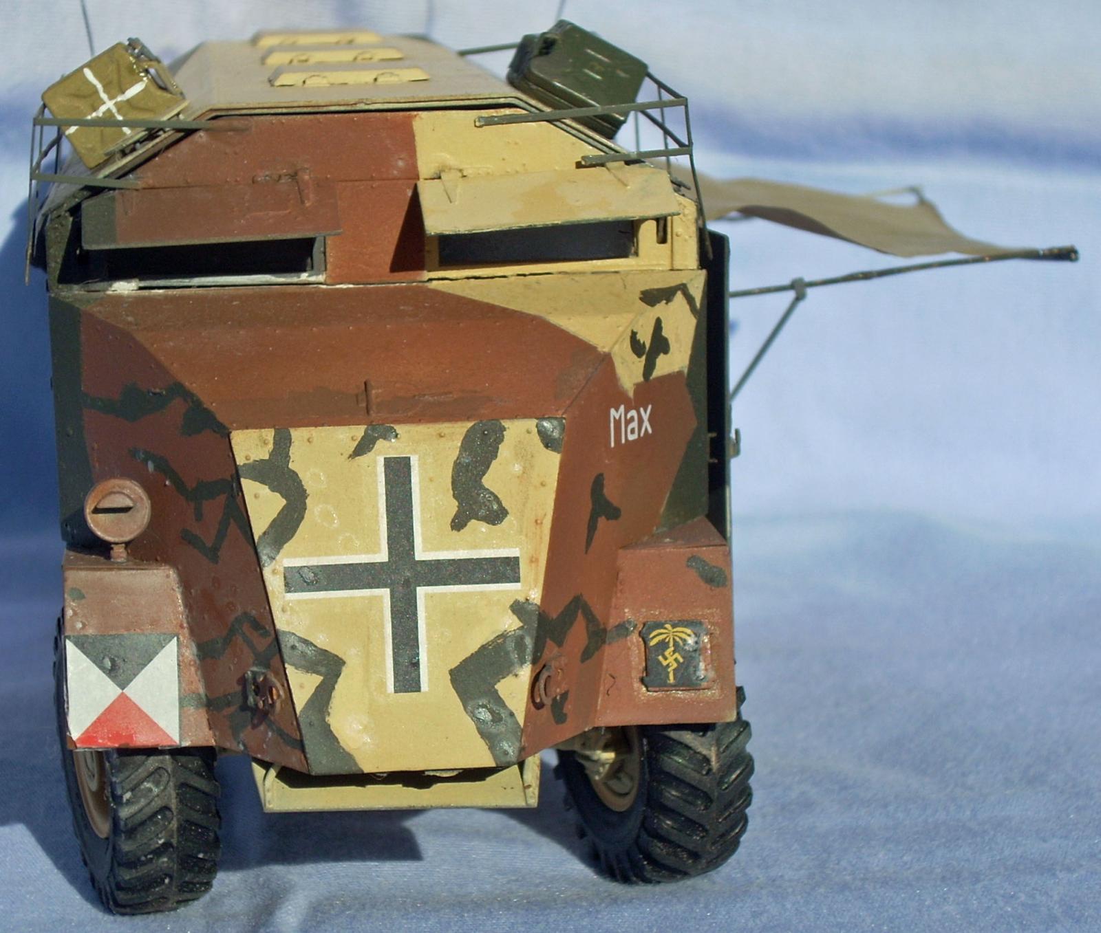
On the night of April 6, 1941 the command vehicles of the Western Desert Force became lost in the darkness. Things got even worse when they bumped into a Recce Unit of the German Deutsches Afrika Korps (DAK). As a result three of the AEC command vehicles, in good condition, became trophies of the commander of the DAK. Lieutenant General Erwin Rommel. The vehicles were nicknamed “Mammut” (Mammoth) by the Germans because of their tall height. Two of them were to be employed by Rommel as headquarter units. They were modified with German diesel engines and named “Max” and “Mortiz” after characters in a German children’s story. The third vehicle went to 5 Leichte Division. All three vehicles served with the DAK throughout the North Africa Campaign. In May 1943 the vehicles were found deserted in Cap Bon, in the northeast corner of Tunisia.
What’s in the Box
- 12 sprues of tan plastic (3 of them duplicates)
- 1 sprue of clear plastic
- 1 bag with nine well detailed resin radios
- 1 bag with rubber four tires
- 1 sheet of photo-etch
- 1 sheet of decals, with markings for all three vehicles
- 1 color paper sheet with British tactical maps.
- 1 sheet of a thick tissue paper to represent the extendable canvas tarp.
- 1 large instruction booklet, totaling 16 pages with 22 steps.
The Instructions
The instructions come in a fully illustrated 8.5x11 booklet. The images are sharp and show the assembly as an exploded view from one side. The first two pages of the instruction booklet have a brief history of the AEC “Dorchester” and the three captured vehicles, in English and Taiwanese. The second page also has a construction illustration key, method for applying decals, and a color list. Colors are provided in a matrix for: Gunze Sangyo Hobby Color, Mr. Color and Mr. Color Spray; Humbrol, Revell, and Lifecolor (very handy if you don’t happen to have Gunze Sangyo paints). The multiple paint call-outs also makes it easy to use any of the online paint conversion tables to cross reference other manufacturers (such as Tamiya or Model Master).
Page three of the instructions has some well drawn sketches of Low Power and High Power command vehicles as well as a sketch of the interior identifying some of the interior components, and sketches of the vehicle in use by the Afrika Korps.
Page 14 is the parts map and order form for broken or missing parts. Pages 15 and 16 are color five view (left side, right side, front, rear, and top) drawings of the three German vehicles for decal placement and painting.
Assembly sequence starts with the well detailed chassis (only the lower part of the engine is provided) (Steps 1 through 5). Steps 6 through 12 cover the detailed interior and main body (more on this later). The drivers station and vehicle front are covered in steps 13 through 16. Step 17 brings the front and body together. Steps 18 and 19 complete the drivers interior and exterior. Steps 20 through 22 cover exterior detail. Step 23 is construction of the roof, while step 24 is for the three types of jerry cans provided. Finally step 25 (misprinted as 22) mates the roof with the body and includes some delicate exterior detail, such as mirrors, antennas, and the photo-etch (PE) stowage racks.
A quick scan of the instructions and two big issues jump out. One is the lack of any color call-outs for the entire frame. The only color is gleaned from the five view drawings in the back that show the frame the same “tan” color as the rest if the vehicle. Not sure how accurate this is, as I can’t imagine spending time to spray paint the underside of a vehicle, but I couldn’t find any online images to counter it. Online images from other builders show the frame as flat black. I went with the main tan body color and only painted the exhaust pipe rust. The other issue is attaching the completed frame to the completed body. The wheels (and assumed frame to which they are attached) simply appear in the final step. I discuss this more later in the text.
Things to Consider Before Starting
This kit has excellent detail and many scale thin parts. Translation, in later stages of the build, handle the vehicle as little as possible, and when handling it use extreme caution. (I broke most every thin part in the kit at least once.) Parts on sprues A and E have extremely fine attachment points so be careful that parts don’t release themselves. One general comment, there are LOTS of identical parts that are handed, so it is very important to remove only one part at a time to avoid using the wrong part. The parts do fit well, are well-engineered, and with a little care and patience, will build into a great model.
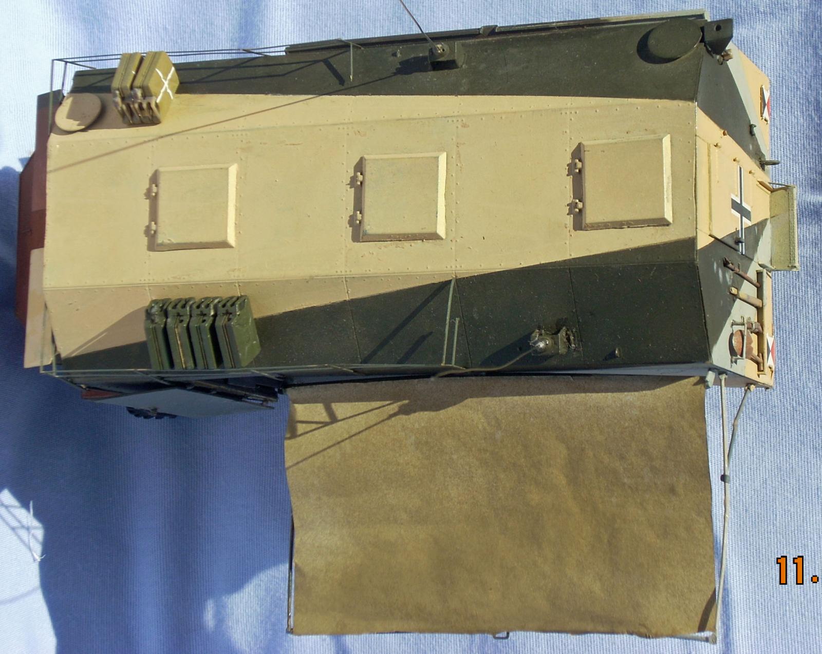
All three doors can be modeled open or closed (even though they are only shown open), as can the armored windshield covers. Although the extended canvas tarp is shown opened on the left side of the vehicle the left and right parts are interchangeable so the open tarp can be placed on the right side if that is one’s preference.
One major drawback is that once the roof goes on in step 25 (22) the detail you worked so hard on in steps 7 through 19 all disappears. Even with the three doors and windshield guards open. To counter this I suggest attaching the PE roof luggage rack only to the sides. Then one can, carefully, slide the roof off the rear to expose the comprehensive interior.
Construction
I start all my builds by scrubbing the sprues with an old toothbrush in warm water and dish soap (Dawn) to remove any residual mold release residue. Another thing to watch is that many parts attach to edges, so make sure that corners remain clean and square when removing mold seams.
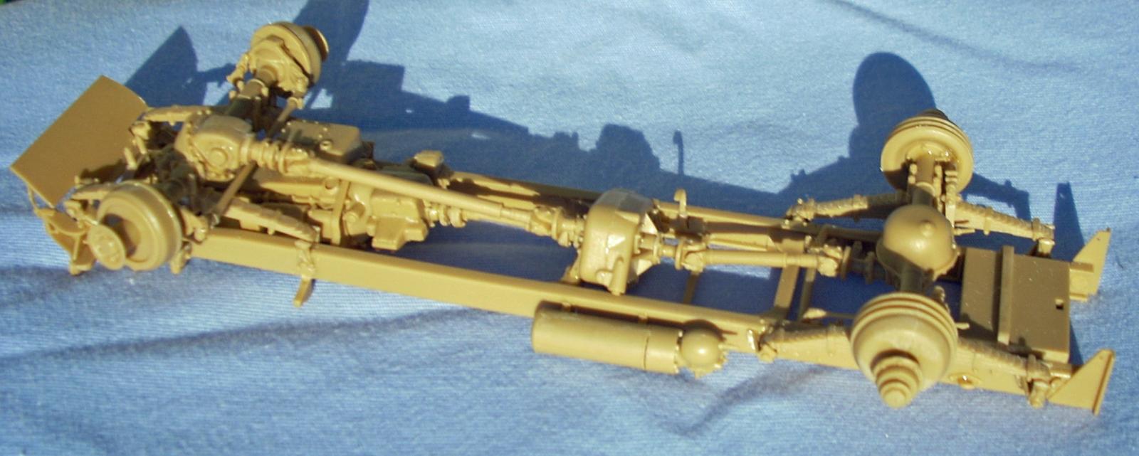
Frame and Suspension
Construction begins with the frame and suspension. The frame is made up of two side rails connected by one front and two middle cross members, the fuel tank, a thin rod and the lower engine compartment. As with many frame build-ups of this type I found it easiest to cement all the cross pieces to one frame side rail then align and glue the opposite frame side rail onto them.
The insets in step 2 have you assemble the left and right rear suspension arms (right side parts A45, A20 and I20, left side parts A45, A19, and I 22) as a subassembly then attach that to the frame. I found it easier to attach I20/I22 to the frame and then attach the A45-A20/A19 bell to them. NOTE: Parts I20/I22 should angle up towards the rear so the end is about 3/16-inch above the frame. This is important as later parts attach to the free ends. It is not clear from the instructions, but the bolt head detail on parts A42 (Step 2) and A41 (Step 3) point out and the single pin inserts into the frame side rail.
Step 2 is the first place not having a step for attaching the completed frame to the completed body requires forethought. Rather than guessing where parts C10 attach to the cross members, I attached them to the underside of the body in step 6. When you look at the body underside it’s not hard to find which holes these parts go in (only one set has the correct spacing for the pins on C10.
In step 3 parts A23 and A24 have a slight angle on the bottom of the bottom “plate,” glue the part parallel to the frame rail. I’m not sure what the leaf spring insets are trying to show as the leaf spring center is identical on both sides. The four leaf springs (I17, 18, 23, and 24) have sink marks and mold seams that are difficult to clean up because of the spring layers. It is not clear from the instruction drawing, but parts E26 and I45 go on top of the frame rails and form a “box” on the frame front.
WARNING: The front leaf springs (I17 and I18) are “handed” AND “ended”. I found that by building most of the front axle from Step 4 I could use it to determine the front and back of the leaf springs. The U-bolts on the axle don’t align with their bottom portions on the leaf spring if incorrect. (This might be what the inset drawings are trying to show. Maybe(?))
Part I44 is an exhaust bracket. It is scale thin and I broke it several times. Where I to do this build again I would wait and attach it directly to the exhaust pipe after that is painted/finished and then glue it to the frame.
In step 4 the rear drive shaft (I33) is angled. To get the correct alignment I first installed the transfer assembly (I3/I4, et. al.), then, while holding I33 lose between them, cemented the rear axle/ differential (I10 etc.). Once the glue setup on the center and rear differentials, I rotated part I33 until the angle aligned then touched the attachments with liquid cement to hold it in place.
The inset shows part A1. These are bolt heads molded onto the “A” sprue that must be “scrapped off” to be attached. (Not an easy task. I lost two before getting a third to stay on my knife blade long enough to place it in a drop of cement already on part I10.) Because the instructions show only a left side view the attachment points for parts I53, I5 and I7 are really vague.
The attachment point of the air brake cylinders (parts I52/A25/A51 and I51/A25/A52) to the front axle is really vague. Upon careful examination there are small pins on parts I51/I52 that fit into equally tiny holes in part A25. The whole brake cylinder assembly angles above the axle (pointing down in the instruction view). For the front differential and drive shaft, I found it easier to glue the upper differential (I25/I29) together first and attach it to the other half on the front axle, let the glue dry, then insert the drive shaft (I32) between the front differential and transfer case. The exhaust pipe is just odd. The engine end angles into the frame instead of into the hole in the lower engine, and the exhaust end points inward instead of outward. I painted and weathered it with rust tones and left it off until after the frame was painted. I then installed it with the exhaust end pointing out and down.
Parts I41 and I 42 have clips on the bottom of the flat arms that attach to parts I20/I22, from Step 2, respectively. Since I20/I22 were installed in Step 2 if you didn’t get the correct angle then it is really difficult to adjust them so that I41/I42 clip on them and still align level with the inner brake disc.
Part E16’s placement is also difficult to work out. And it isn’t helped by the fact that the inset is with the frame right-side up. It fits between and attaches to Parts I38/I39 from Step 3. The free end of Parts E42 and E43 actually do remain loose.
I left the rubber tires off until after painting. If you choose to do this, only push fit the wheel caps (A46 [front] and A40 [rear]) so the wheel assembly can be removed later and the tires pressed on.
That completes the chassis.
One other item of note, in Step 4 if you don’t cement the inner wheel bearings (Parts A38/A39) to their respective axle ends the direction of the front wheels can be changed from just straight. I found a build online that went even further and drilled out the holes in part I5, and replaced the attachment point on the axle to make the front axle steerable. The only disadvantage to a fully steerable front end is that the steering linkage (Parts I40/I53/I54) cannot be attached to the axle.
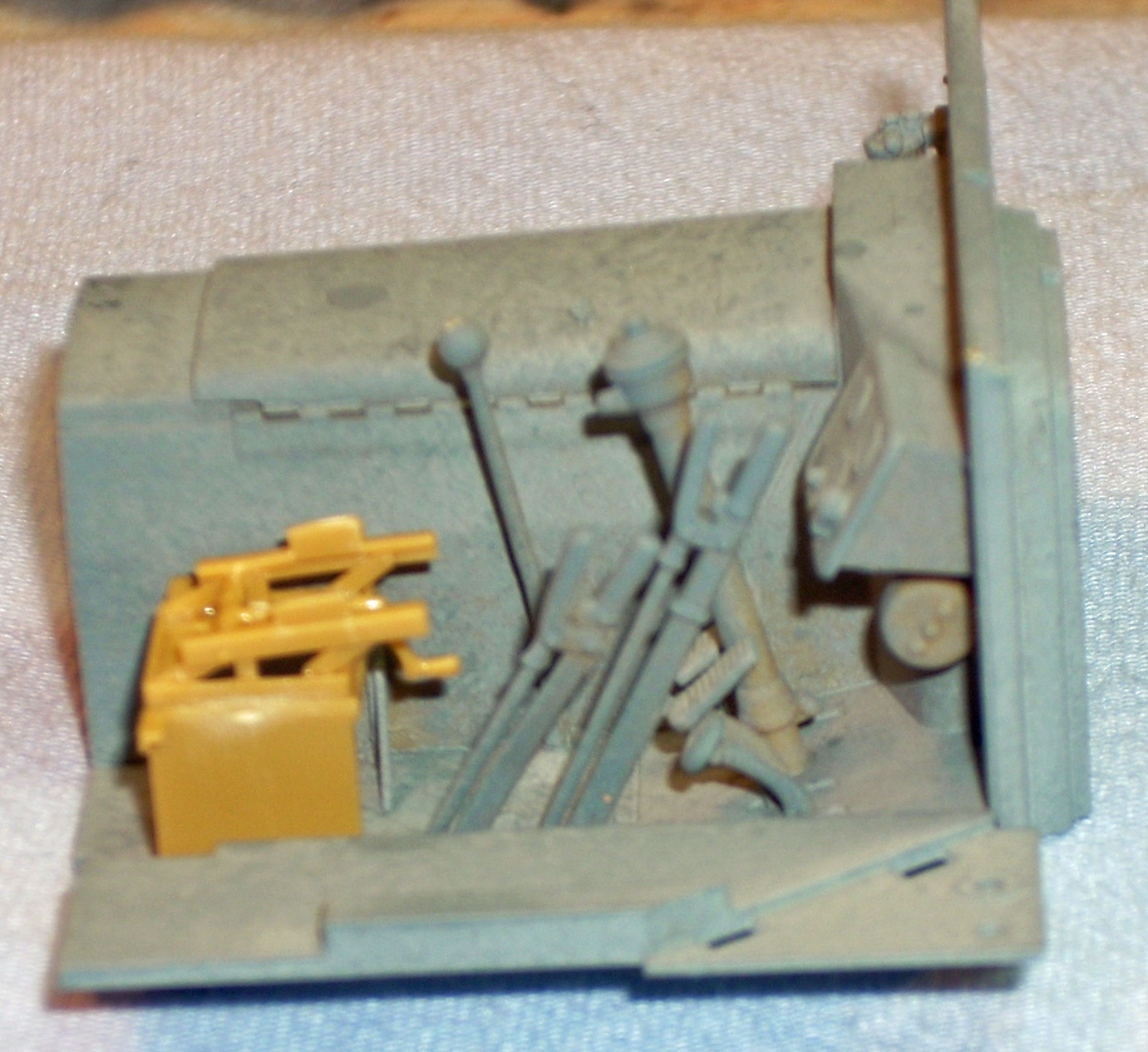
The Command Center Interior and Drivers’ Compartment
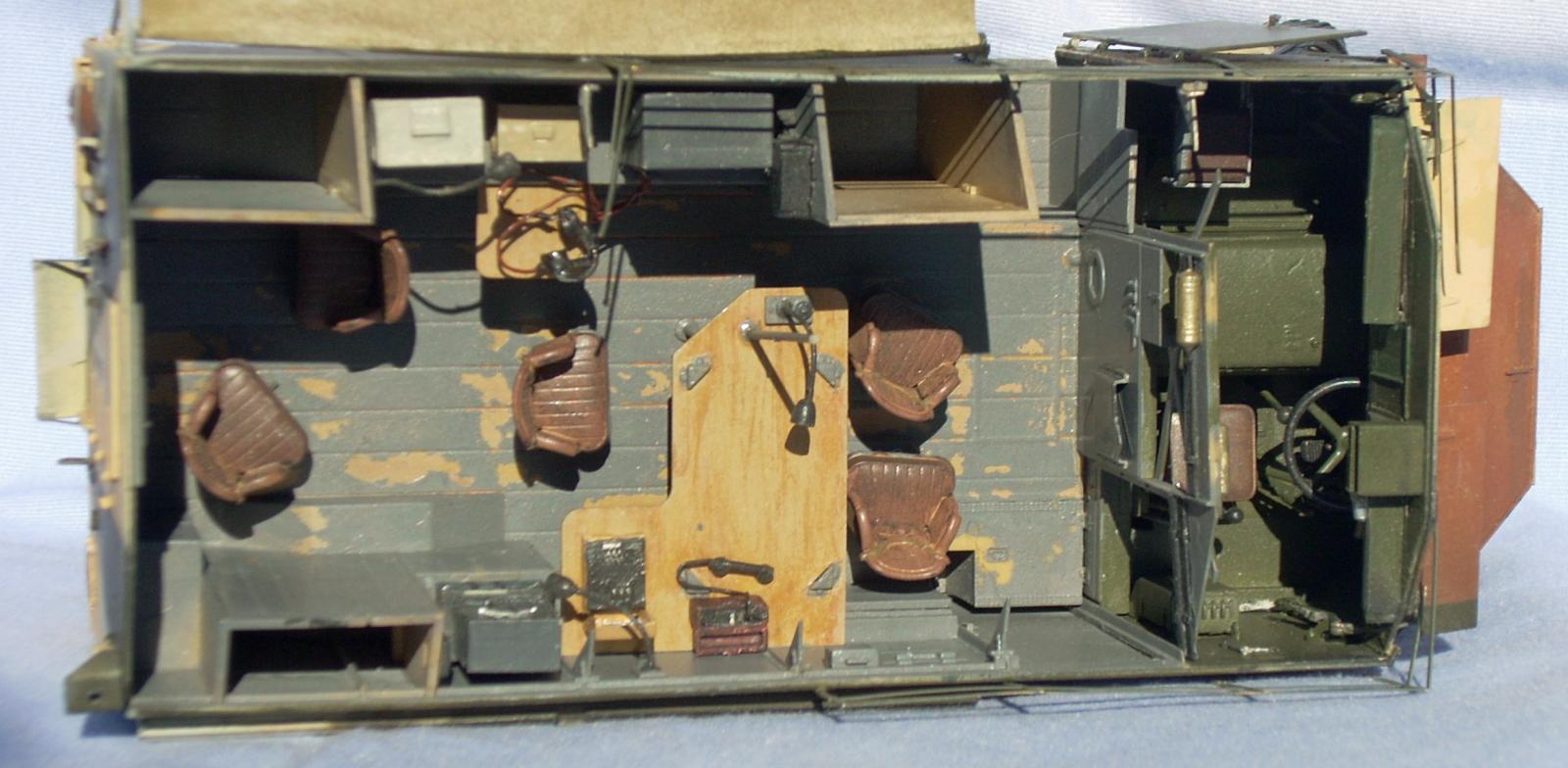
The body interior and drivers’ compartment are extremely well detailed. AFV Club includes excellent resin radios and field phone for use in the body. The down side is it will all pretty much disappear if the roof is permanently attached (more on that later).
In Step 6 it shows x4 batteries, but there are only 2 parts F12. Parts F13 are the other two battery tops. The drawing of the PE battery holder suggests that the end of the bottom pieces (G9 and G11) extend past the edge of the frame. I found the braces were too short and could only be extend beyond the frame on one side. I chose the side facing out and the front.
Parts D19/D21 in Step 6 and E35/D18 in Step 7 are covers for the entry stairs. If you are going to use the completed vehicle in a diorama then leave these off until the end so they can be glued in an open position. (Note: To show either D18/D19 open one will have to shave off the hinges so the cover sits flat against the front wall.) Step 6 is also where I cemented Parts C10 to the bottom of the body. These parts fit between the rails. It is easy to determine where they go as only one set of holes line up with the pins on C10.
In Step 7 the upper connection arrow for part C21 is incorrect. The part should be angled with the tabs on the lower left interlocked so the slot on the upper left fits over the internal wall brace. The same applies for part C22 on the left-hand side in Step 10.
At this stage I deviated from the instructions attaching the small interior details, except clear part H9, including the roof braces (parts C19). The actual position of these is vague. It took me a couple of tries before I settled on the small (tiny) angles attach to the interior wall, while the brace itself attached to the center of the wall braces. The break in angle of the brace must be flush with the top of the wall. Too short and the braces don’t reach the roof. Too high and the roof doesn’t sit flush to the side walls. I then attached the right side wall to the floor. I also attached both parts of the rear wall (C6 and D7 (shown in Step 12). I built the cabinet as shown, but left it loose to paint separately. I also constructed the seat bottoms (parts K3/K6/K8, Step 9) and attached them to the floor. I then painted and weather the interior of the right side wall, and floor. I painted and weathered the right-hand cabinets before attaching them to the right-hand wall.
Take extra care when attaching the side walls and rear to make sure everything is plumb and square. One way to ensure this is to start gluing the side wall to the floor at the door. The steps in the floor fit between the jams on the side wall. This will also ensure that the rear of the side wall doesn’t extend too far past the rear of the floor and interfere with the rear wall.
Steps 8 and 10 show the side wall ahead of the doors (extending past the floor front) as being painted silver, maybe to represent natural metal. I was unable to find any reference photos that indicated these walls were natural metal. Most online builds show these walls painted the same Dark Sea Gray as the rest of the wall, but I chose to paint them the same Khaki Green as the drivers’ compartment.
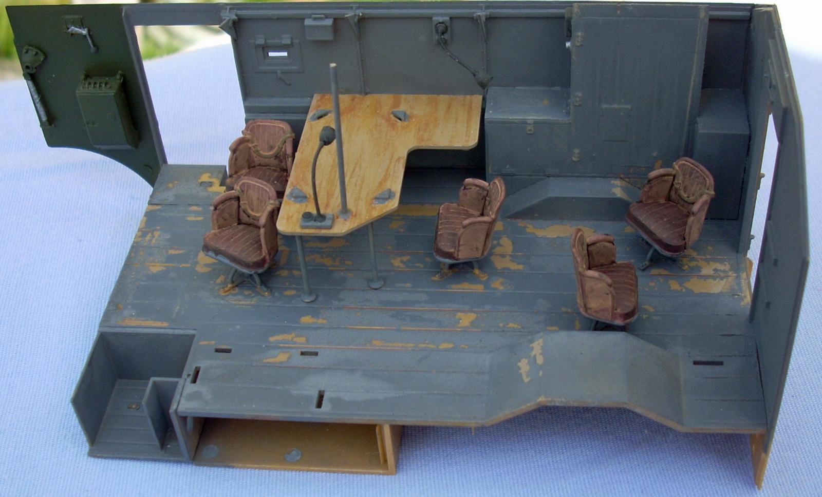
Having painted and weathered the interior walls and floor I attached the table, swivel chair seats, and radios as shown in the instructions. The resin radios are incredibly detailed and careful painting really makes the details pop. One minor drawback is with such exquisite radios it would have been nice to have a head set and microphone to go with them. I scratch built a set of headphones and wired them to one of the radios. I also wired the field phone handset to the phone box. I had difficulty painting the resin radios as paint didn’t want to stick even after multiple soapy warm water scrubs and primer.
In Step 10 I added the rear flap C22, small handles (E37 and E41), and roof braces (C19) to the left-side wall before painting and weathering. See above for notes on attaching the roof braces (C19). I attached the wall mounted seat after painting and weathering the interior wall. As I did above I built the left-side cabinets and painted and weathered them separately. I also painted and weathered the pull-out shelf (L14) separately from the cabinets and installed it before attaching the whole set to the floor and left-side wall. Use the same approach as described above for the right wall to attach the left wall.
The drivers’ compartment is built-up over three steps (13 thru 15). Part B7 had a large ring of flash around it, so be careful when removing it from the sprue. Step 14 shows an option of hand brake levers (B16 or B17). But there are location slots for both levers in the floor (part E1). An online search found only one image of the chassis and it showed two levers. Also, most of the online builds used both levers, so I also went with both. Make sure both levers are angled forward or else they interfere with the driver’s seat. Part B16 is also “kinked” to the right when installed properly. I waited to install the black steering wheel (part B4) and red brown seat cushion (part B2) until after painting the khaki green interior color. In step 15 the drivers’ side of the wall is called out as being painted silver. I went with the khaki green like on the side walls. After painting both sides of the wall I installed the pre-painted smaller parts.
The engine compartment goes together easily. The only item of note is the inset to remove the hinges if you’re building Max or Mortiz.
Completing the Body and Front Armor
The back drivers’ compartment wall sits ON TOP of the floor. Make sure the hinges for the stair covers are aligned. Follow Step 18 and 19 and attach the front armor plate (part E2) BEFORE adding the windshield boxes. I didn’t and the plate bowed and required filling.
Again I painted all the parts khaki green instead of the called out silver.
The levers for the armored windshield covers (parts E34/E45 and E44/E49) are extremely thin, fragile, and finicky. I had luck by gluing the levers (E34/E45 and E49/E44) together first, then slid the front (Parts E34 and E49) through the slot in the front plate, and then glued the lever handle (parts E44 and E45) to the side walls. While the glue was still soft I held the armor covers (E10 and E11) in place and adjusted the lever assemblies until they fit into the slots on the armor covers. As an aside I built both sides with the covers up, but they can be built with both closed, or as shown in the instructions with one open and one closed.
In Step 19 it is easier to pre-paint the framing on clear parts H1 and H2 before installing the wipers and wiper motors (which should also be pre-painted).
Exterior Detail
CAUTIONARY NOTE: Use extreme care when handling the model from this point on!!
Steps 20 through 22 add details to the exterior. Parts D15 and D17 are interchangeable so the awning can be built extended on either the left (as instructed) or right side. The lower awning brackets and pins (Parts C24 and C20) are minute at best, and, as a result, extremely fragile. I wasn’t as careful as I should have been and smashed/lost all the lower awning brackets (C24).
CAUTIONARY NOTE: I recommend NOT attaching the awing frame until after painting the vehicle!!
One can construct the awning frame in step 20. But DO NOT ATTACH until after painting the vehicle. The frame parts are scale thin, and require excessive caution when handling, (I broke all of them at least once, and had the ends break-off of parts C12). PE part G5 can be difficult to install and have the correct angle on the awning brace (part C12). There are tiny pins on both ends of the awning brace (part C12). Using great care one can twist C12 into place between the brackets (C24) so the pins fit into the holes in C24 and the part will move freely. Next I bent part G5 into an open U-shape. Then, with part C12 locked into the brackets (C24) and held at the correct angle/location I superglued one side of the U to the very small pin on one side of C12. I then squeezed the U closed so that the hole in the unglued side fit over the pin on C12. I then applied superglue this side.
Step 20 also shows the interior side of the open door painted a Radome/Flat white mix. This struck me as odd as it would make the doors stand out against the dark green camouflage to come. I painted the door interiors the same dark sea gray as the command center interior. The PE door handles (parts G16 and G17) are different lengths. The outside handles (G17) are the longer ones.
Step 22 shows the right side and rear doors being attached closed. This is fine if you don’t mind never seeing all the work you put into building/painting, and weathering the command center interior. I recommend gluing them open or, as I did, attach them with a couple of dots Elmer’s white glue, just enough that they stay on, but can still be removed to show off the inside.
Part D29 (Step 22) is another extremely thin and fragile part (mine broke just clipping it from the sprue), so handle with care.
Roof
The roof hatches can be modeled open or closed. Again, closed is fine if you don’t mind not seeing the interior. I left mine loose. Although not shown in the instructions there are three clear windows that will fit into the inner roof hatch openings (L9, L10, and K2). These may just be left over from the Dorchester kit, but I didn’t use them.
Final Assembly
Step 24 builds the jerry cans. Although it shows each side and filler as options there are actually only parts to build two of each model with two of each filler.
Step 25 (22) is the final assembly. As noted at the start of this review. This is the step where the frame suddenly appears under the body. It was straight forward to attach the two back cross members to parts C10 that were previously attached to the floor. What was more difficult was determining how (or if) the front of the frame attached to the body. The best I worked out was the engine side mounts (parts I49/I50) attach to the bottom of the drivers’ compartment just behind the front wheel well.
Once more, as I stated at the start of this review, I glued the PE luggage rails (G18/G19) to the sides only. This way one can remove the roof by C…A...R…E…F…U…L…L…Y sliding the roof of the back of the body. Use extreme care, remembering that there are thin roof supports attached to the interior braces.
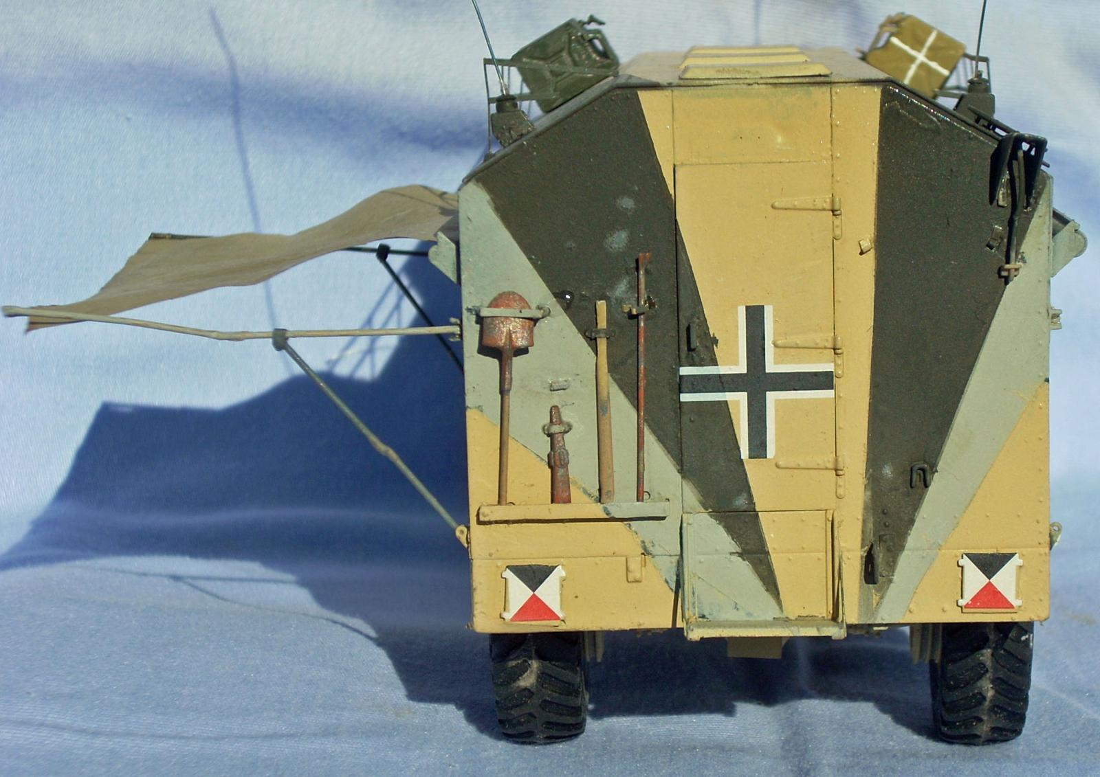
At this point it is best to paint the exterior camouflage then attach the awning and “canvas” (tissue paper) tarp awning. Though not shown in the instructions, there is a selection of tools (along with a selection of British firearms and radios) on sprue (outline) E. I painted them and slid them under the PE braces on the rear wall as shown on the rear color views.
Painting and Finish
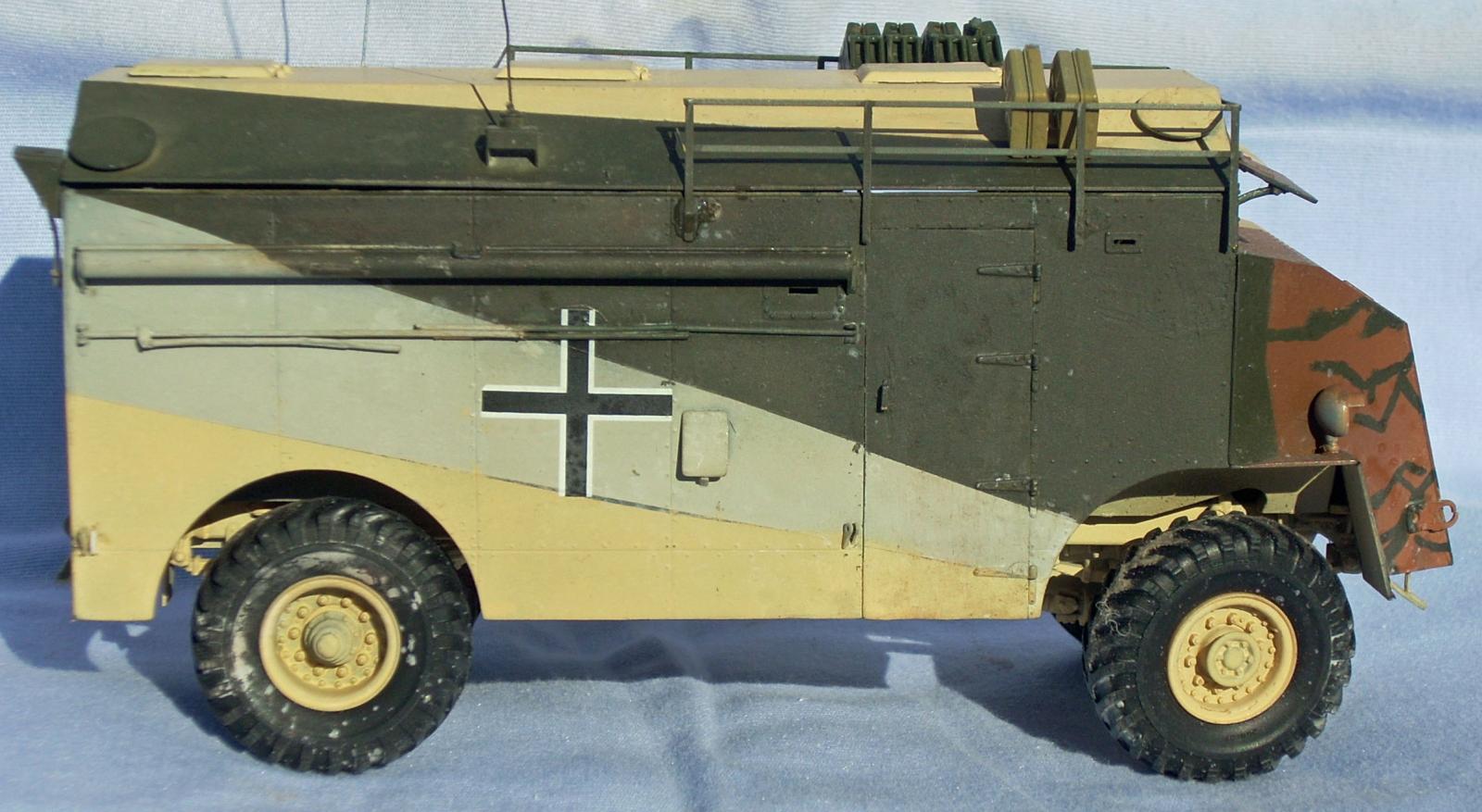
The camouflage on all three vehicle uses the same three color scheme RLM71 Dark Green, FS26440 Gray, and a 2-to-1 mix of Radome and flat white. These are applied in broad angled swaths with hard edges. “Max” has the hood and front armor plate painted RLM79 Sandy Brown, with hard edged “squiggles” in RLM71 Dark Green. I used an online paint conversion chart to find which of the paints I owned matched with the paints called out. I am terrible at mixing colors so opted for straight FS33613 Radome Tan (MMP-070) from Mission Models as a replacement for the Radome/flat white mix. At least to my eyes the straight Mission Models paint appeared slightly lighter than the straight Mr. Color paint.
(Note: I thin all acrylic paints 50/50 with Tamiya Acrylic Thinner. I mix the paint in the color cup with a round toothpick stuck in the end to prevent the paint mix from pouring out. I fill and empty a disposable pipette until mixed. Then attach the color cup on my Aztec 401 airbrush, Black tip (0.40 High flow acrylic), set at 20 lbs. pressure.)
Primer and Base Coat
All the interior walls, floor, cabinets, fixtures and drivers compartment bits-and-pieces were primed with Krylon ColorMaxx Gray Primer.
The frame and body exterior were primed with Krylon ColorMaxx Flat Black Paint+Primer. Both of these products spray on “fire-hose thick” but dry down to a tight coat that shows all the detail (and any flaws). Let the primer coats dry and de-gas at least overnight (though a full 24-hours is better).
Interior, Tools, and other Details
After priming with Krylon Gray Primer the interior wooden parts (floor (Part C1), and assembled left and right hand cabinets) were painted Tamiya Dark Yellow from a spray can (TS-3). After drying I applied an uneven, light coating of Burnt Umber oil paint. Allow this to dry for 15 to minutes then wipe off in the direction of the wood grain. You don’t want to wipe it off completely, just enough to make streaks to simulate wood grain. Allow the oil paints to dry for a couple of days between applications. I repeat the same coat-streaking wipe-dry process with Burnt Sienna and finally Yellow Ochre oil paints. I used this same technique on the table and pull-out shelf, but these were base coated with Model Master Acryl Wood (no. 4673).
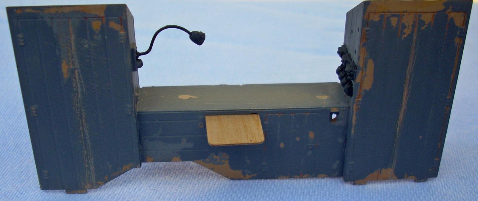
After the last oil coat I let the model dry for about a week, you want the oils well set before moving to the next step, which is: Apply a coat of hairspray as a chipping medium and allow it to dry (about five to ten minutes). Any brand will do, I use TRESemme’ Extra Hold. Over the hairspray I apply the main interior color, Tamiya Dark Sea Grey (XF-54) using my airbrush. Give this coat about 15 to 20-minutes to dry (so it is dry-to-the-touch). Once dry, use an old stiff bristle paint brush dipped in water to gently scrub the floor and cabinets. The water will activate the hairspray so as you scrub the grey paint will begin to loosen creating chips. Be careful not to scrub to hard or use too much water as this may remove too much paint. I made heavier wear in areas that would get heavier use, such as around the swivel chairs and edges of cabinet doors. The images show views of the painted and weathered command compartment.
When spraying the floor and cabinets mix enough grey to spray the interior of the side walls and the back of the driver’s compartment wall. The other interior components swivel seats, radios, lamp, table, etc., were painted per the instruction call-outs. I substituted the following colors for those listed in the instructions: Tamiya XF-2 Flat White, XF-49 Khaki, XF-61 Dark Green, XF-63 German Grey, XF-64 Red Brown, XF‑85 Rubber Black, Lifecolor LC11 Bright Green, and Model Master Acryl Brass (no. 4872) and Wood (no. 4673). For the interior parts that are silver I used Model Master Acryl Steel (no. 4979) as my jar is a medium silver color. For the radio silver I wanted a brighter color so I used Mission Models Aluminum (MMM-003).
The driver’s compartment and inside of the hood were airbrushed Mr. Color H80/C54 Khaki Green.
Camouflage Coats
After the primer coat and masking the front windows, the roof, lower sides, hood front, and upper right front were sprayed with Mission Models Radome, allowing some of what’s underneath to show through along the edges and in recesses. Let this dry for a good 24-hours. (Note: Best to work from light to dark colors.)
I then masked the Radome color on the sides and rear for the gray. (The color call out is for FS26440, but FS36440 [flat gull gray] is essentially the same color [and much easier to find].) I used Model Master enamel flat gull gray (No. 1730) thinned with Testors airbrush thinner, and sprayed at 20-psi. This coat is then left to dry for 24-hours.
Leaving the Radome areas masked I mask off the flat gull gray areas. I also mask the Radome on the front and roof. After masking I applied Tamiya XF-61 Dark Green, and let this coat dry for 24-hours. After drying I masked the front and sprayed Model Master Enamel Leather for the sandy Brown color. I then removed all the masks and made any touch-ups that were needed.
Once dry I applied a coat of Model Master Gloss Clear Lacquer from a spray can in preparation for decaling.
Decals
I used the Red and Blue MicroSol/MicroSet products to apply the decals without any problems. Once dry, I gave the entire vehicle a good coat of Model Master Gloss Flat Lacquer to seal the decals and prepare the surfaces for weathering.
Finishing Up
I haven’t weathered the exterior yet, but do plan to do so at some point.
After having completed painting and the majority of handling the model I would suggest that now would be a safe time to attach the canopy frame and tarp. Use extra care as the parts are scale thin and easily broken. I broke all the frame parts at least once and a couple broke just removing them from the sprue.
Conclusion
This is only my second AFV Club build. I find that the model is well detailed, but the scale thin parts take extra effort in handling, both when removing them from the sprue and after attachment to the model.
As stated earlier my biggest complaint is the lack of a step for attaching the frame to the body. In attempting the attachment in Step 25 (22) the front wheel wells interfered with my efforts to get the frame in. Once I got parts I49/I50 past the interference there wasn’t a way to glue them on, so the front of my frame is loose, but held in place because the brackets (parts I49/I50) won’t drop out.
My second complaint isn’t as major as the previous one. By showing only views from the left front side in each step the attachment of parts to the back or right side of an assembly or part is vague in some steps. Not a big deal, but it makes for some creative placement.
I recommend this kit for intermediate modelers. Anyone with other AFV Club builds under-their-belt should not have any troubles this kit. The scale thin parts require care when removing them from the sprue and especially once attached to the model. All things considered, the build went relatively smoothly and the result is worth the effort. The completed model is certainly an interesting project.
I would like to thank AFV Club for providing this kit for review, and to IPMS USA for giving me the opportunity to build it.


Comments
Add new comment
This site is protected by reCAPTCHA and the Google Privacy Policy and Terms of Service apply.
Similar Reviews