
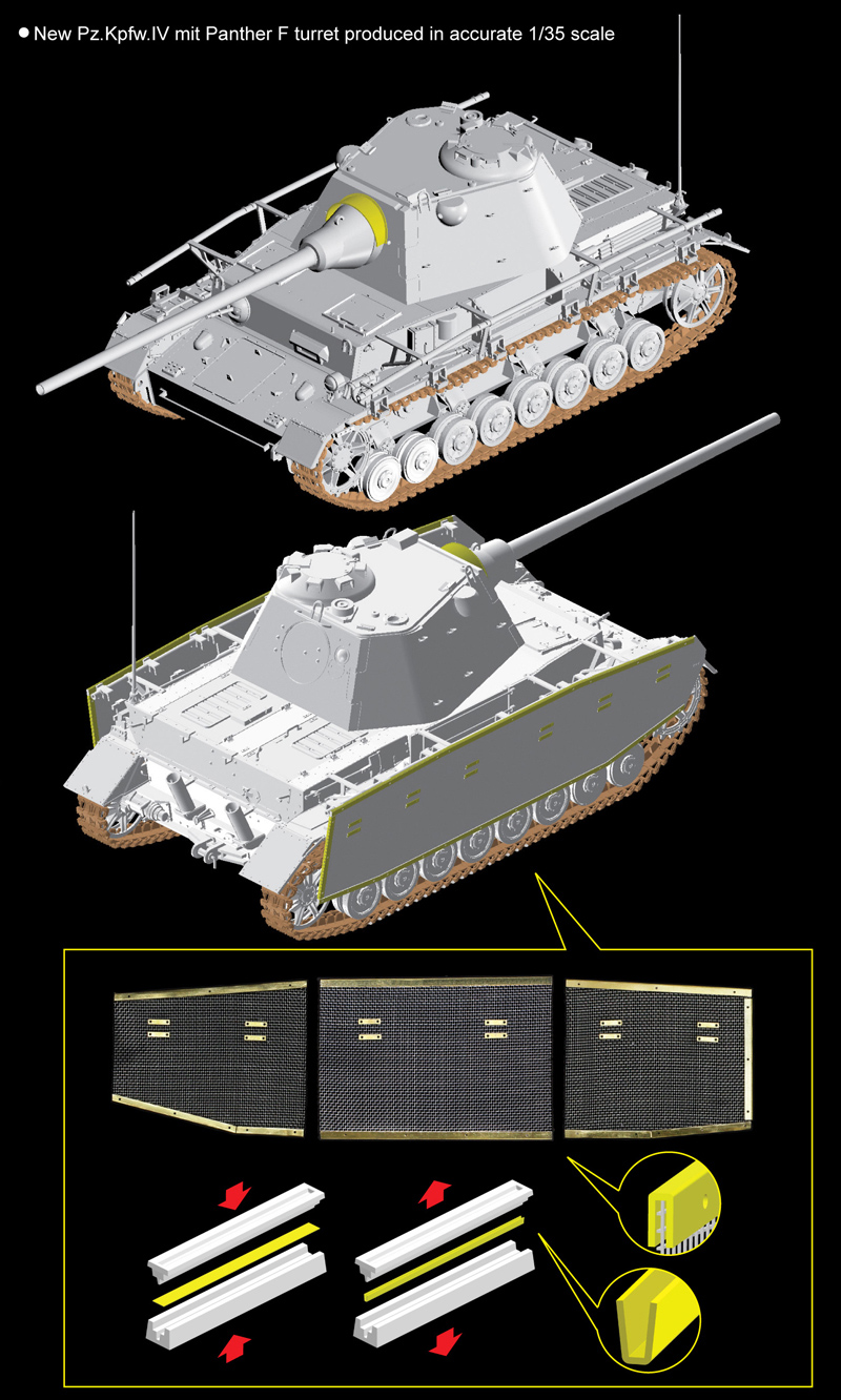
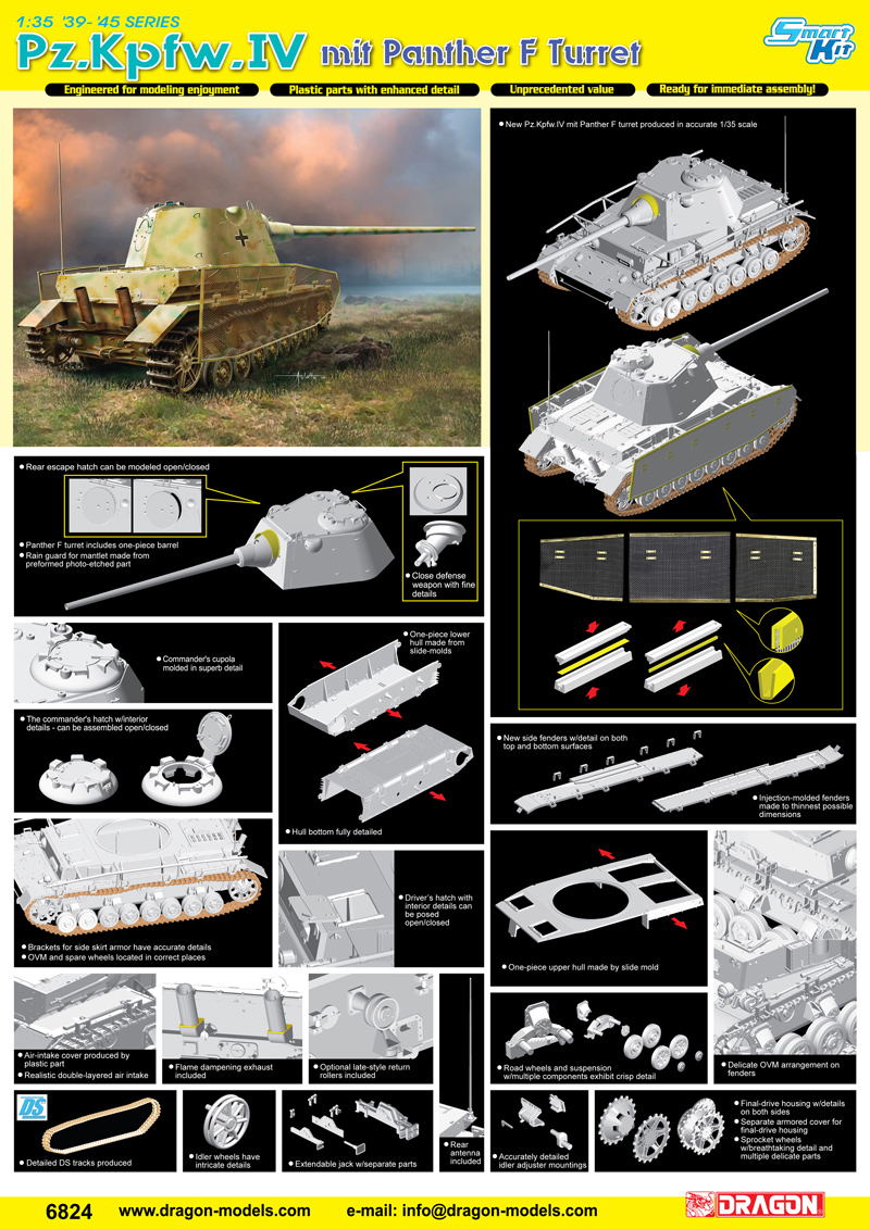
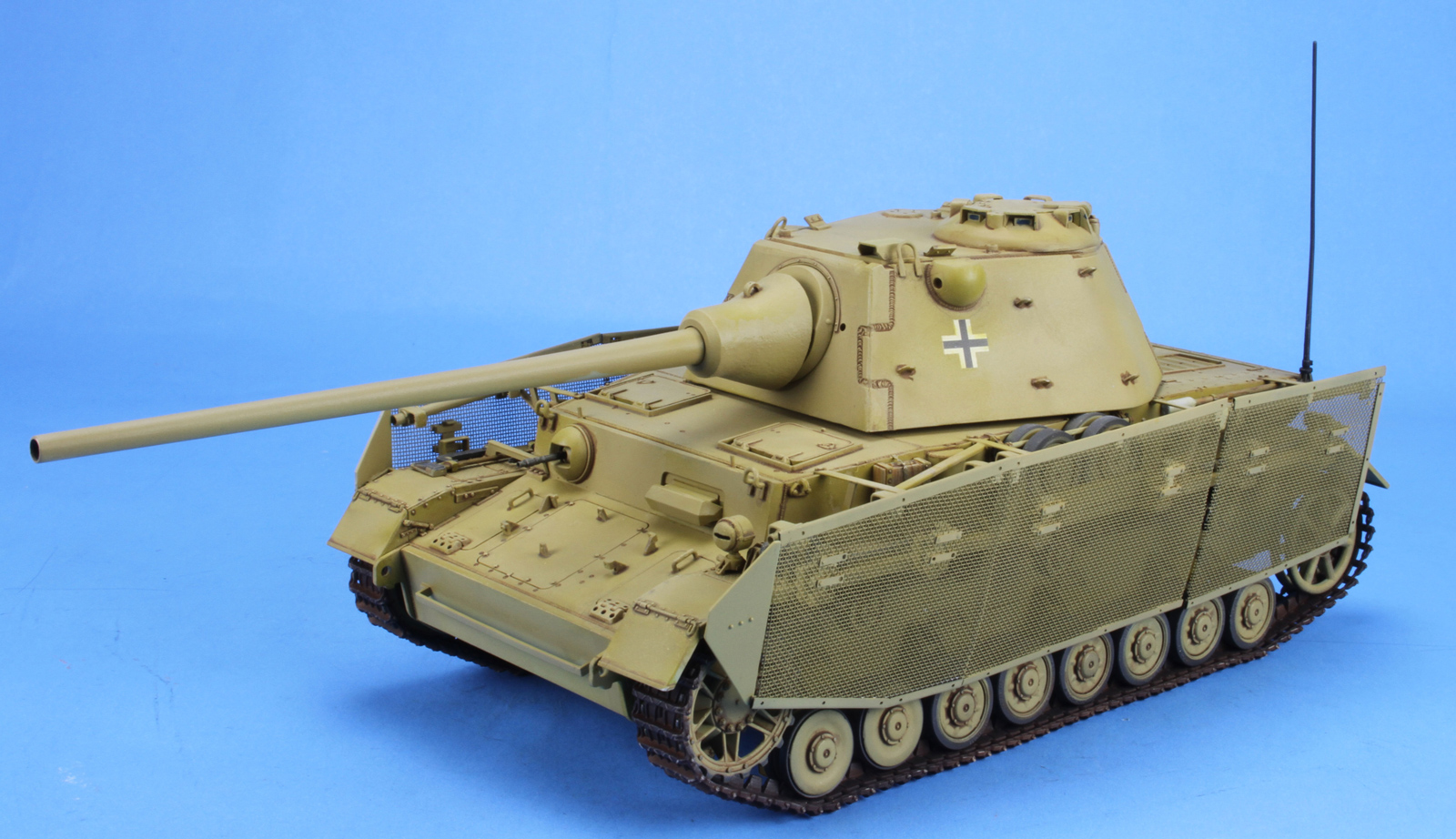
Pz.Kpfw.IV mit Panther F Turret
This kit is a model of a proposed design by the Krupp AG company. The thought was to upgrade the firepower of the Pz IV with the newly designed Panther turret with its 7.5cm KwK L/70 gun. Nothing came from this proposal and the painting schemes are pure conjecture.
This is a multimedia kit comprised of 477+ styrene parts, DS tracks, 1 photo etched parts fret, and much worse set of instructions. They need to be reviewed very carefully before gluing any parts together.
This kit follows Dragon's current practice of taking sprues from different kits, adding a couple of sprues of new parts, and creating a variant that has not been done before. They have also done the same for the instructions, taking from multiple instructions and trying to paste them together to create a new set for the variant. They did not take the time to review the results or even try to build the kit from the instructions to see if there were any problems, conflicts or omissions. Be careful to read and look ahead before applying glue.
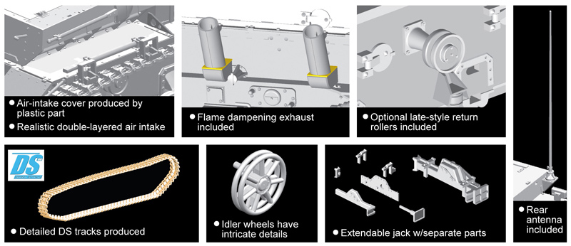
Step 1. This step is the assembly of the drive sprockets, road wheels (includes some new steel rimmed wheels), return rollers, and idler wheels.
Step 2. This step assembles the rear plate and the exhaust pipes. The towing hitch can be configured in two types. The problem here is that the instructions show the hitch glued to the lower left side of the rear plate instead of in the center where it should be.
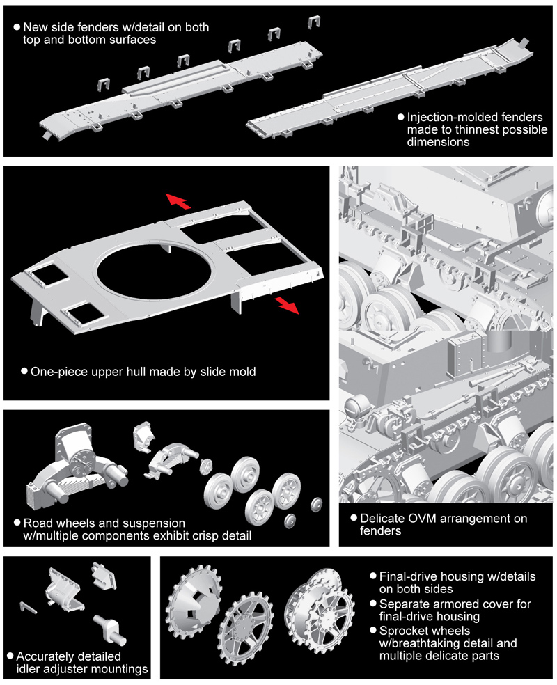
Step 3 & 4. This step attaches the basic items of the running gear to the hull along with the front and rear plates are attached in this step.
Step 5. This step builds the front upper hull plate and attaches the drive sprocket, idler wheel and the road wheels. The instructions show the leaf springs being attached to the D13(D15) plates, but those plates are shown being attached to the hull in step 4. It should not matter which step you use to attach these plates, but it is an example of how the instructions can be confusing.
Step 6. This step builds the two fenders by attaching the Schurzen holding points (T3). The fenders are then attached to the hull. Some fitting will be required here, make sure that you dry-fit before applying glue.
Step 7. This step attaches the hatches to the rear engine deck. You also build the subassemblies of the air intakes. There is an option here between the empty spare track rack (C12) and the addition of the full spare track rack (C15 & C14). The instructions show the option arrow pointing towards the air intake subassemblies instead of down towards the empty rack (C12). The left side upper plate (N6) shows adding part air intake cover (F7) with a possible optional item, but there is no other choice. Again the instructions are confusing. In this step you can add the retaining chain to the jack block (E15), but the instructions show this being done in step 11.
Step 8. This step builds the hull machine gun and completes the front plate that is in front of the driver along with the rear plate. I suggest that you leave tow cable storage rods (A52) off the rear plate build until the very end, as my experience has shown that these will be broken off before you get to the painting stage.
Step 9 & 10. This step completes the rear engine deck, the side plates, air intake subassemblies, and the front plate to the upper hull. The upper hull is then mated to the lower hull.
Step 11 & 12. This step adds the exterior tools, lights and fire extinguisher to the fenders. I have found that leaving these items off and painting them separately allows for more complete painting and weathering of both the individual items and the hull. In this variant, if you wait till the Schurzen brackets are attached, the access to these tools for painting is very limited.
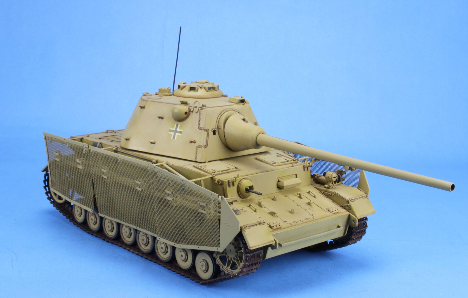
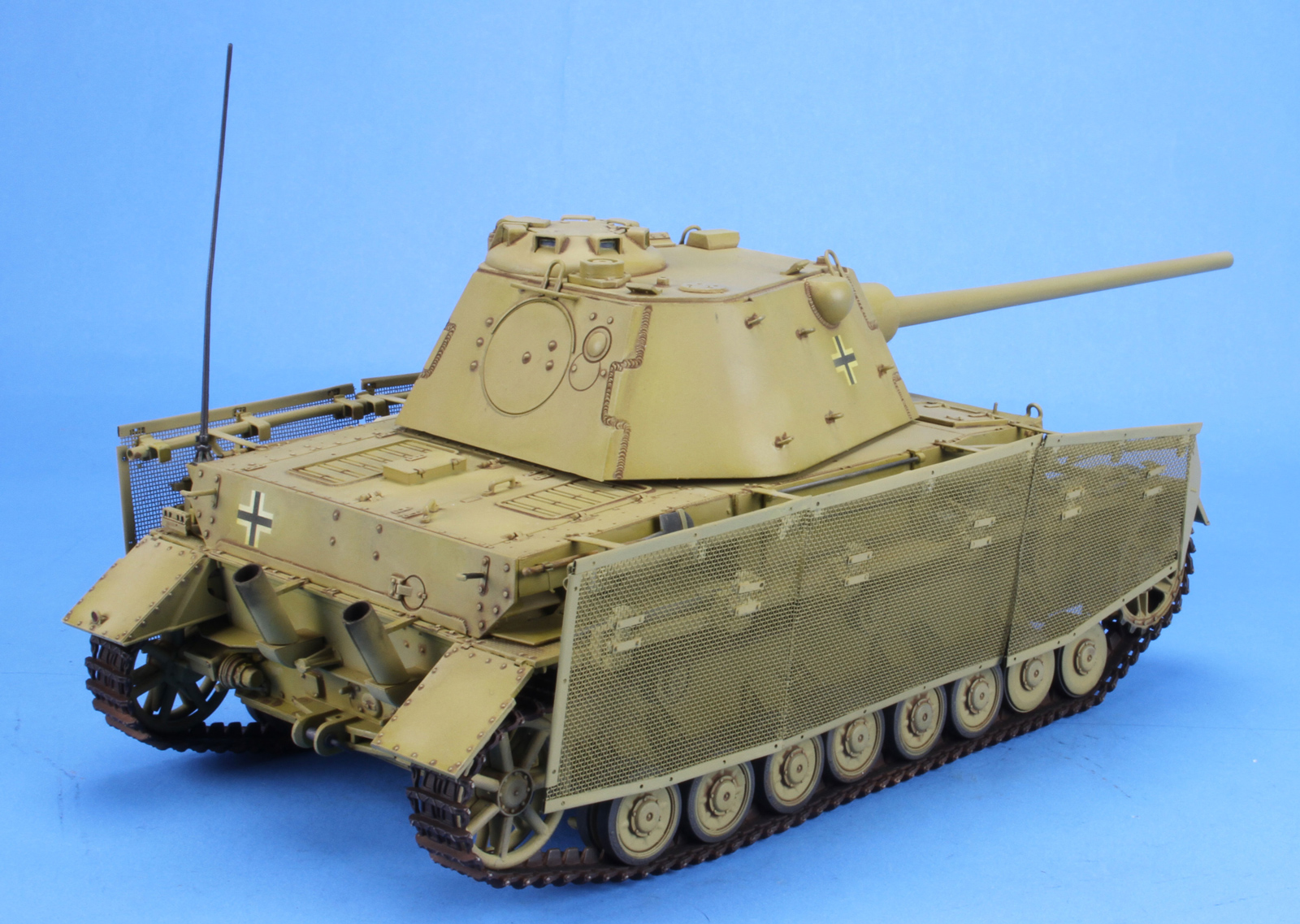
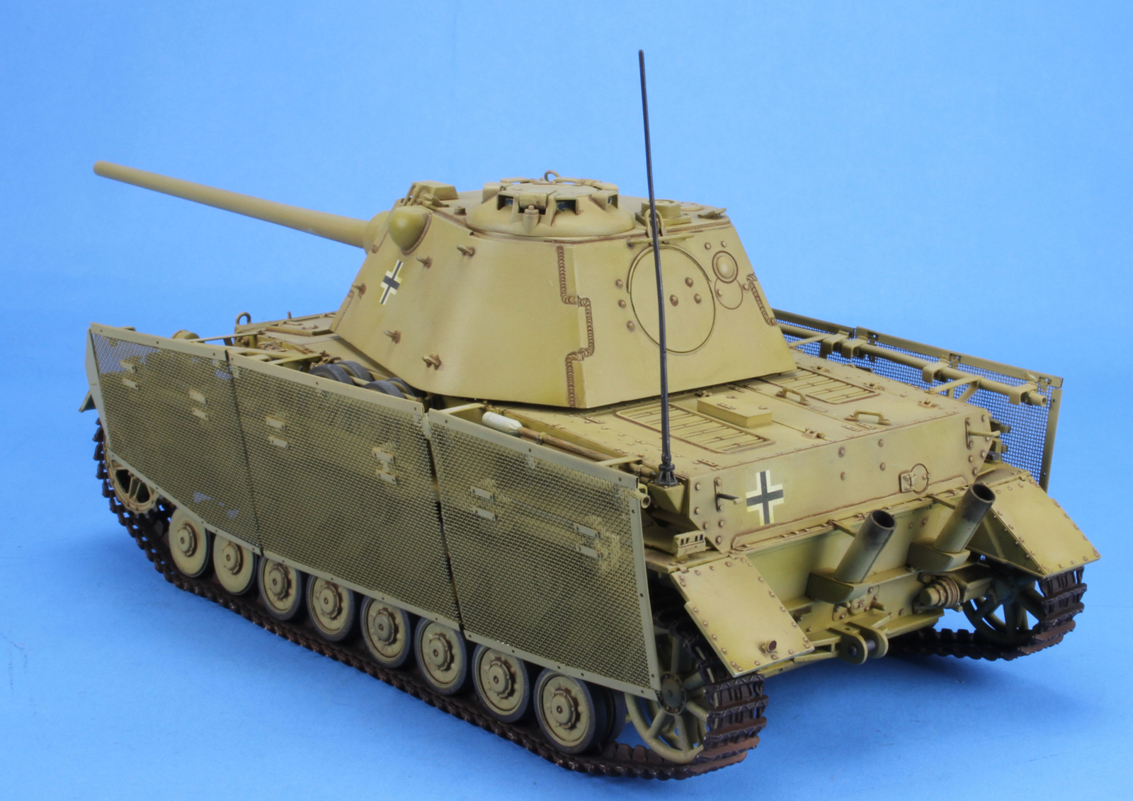
Step 13. This step is a choice between with or without the Schurzen (sideskirts). I chose with the Schurzen. Schurzen bracket brace (T31 and T32) are miss marked. T31 on the left side should be T32 and T32 on the right side should be T31. You have a choice of Schurzen hanging rod between T1/T2 (to install the side plates) and T33/T34 (to leave the side plates off)
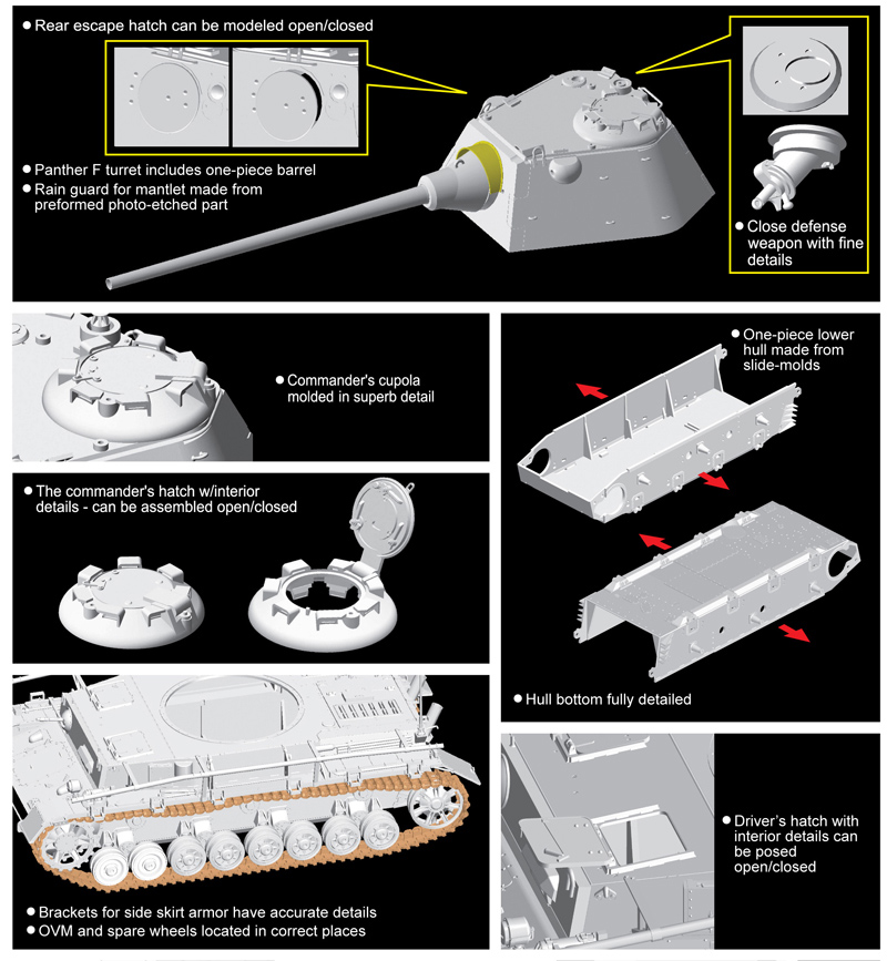
Step 14. This step finishes the gun and attaches it to the front turret plate.
Step 15. This step starts the turret by adding the rear hatch to the rear plate. There is very little inside the turret so leaving the hatch open is not really much of an option.
Step 16. This step builds the commanders cupola. The hatch can be left open if desired. Again there is not much to see in the turret, but there is enough detail of the cupola that inserting a figure to block the view into the interior will be okay but you can still see the interior of the cupola and its detail.
Step 17 & 18. This final step finishes the turret by adding the front plate and the bottom turret ring plate.
Step 19. This step builds the Schurzen (sideskirts). You will need to install the DS Tracks prior to installing the Schurzen (sideskirts) as you will have little to no room after the mesh installation. The wire mesh is precut to the exact dimension as shown in the instructions. The photo etch edge railings need to be annealed prior to using the forms T35 & T36. Once they are softened the forms work well. I did use a pair of pliers to do the compression forming. I had thought the precut grooves in the railings would match up with the indentations on T1 & T2, but they don’t. What I ended up doing was gluing the mesh bracket T10 to the mesh along with the MA4 photo etch plates. The instructions show the correct location for these bracket. You might want to copy the instructions and use them as a template for the placement of the mesh bracket T10. I then glued the upper mesh brackets (T25) to the railing rod T1/T2 in the slots indicated. After I finished painting and weathering the model and the Schurzen (sideskirts) I inserted them into the brackets on the fenders. That is the T10 bracket into the T3 bracket on the fender. These are sturdy enough to hold the Schurzen (sideskirts) in place. I then used superglue to attach the top of the Schurzen (sideskirts) to the upper mesh brackets (T25). Some of the upper mesh brackets will match the groove in the top railings, some will not. But, the Schurzen (sideskirts) will be glued in place and will not be removable.
Molding
I found the molding to be clean, with no sink marks and few ejector pin marks on the newer sprues. The mold seams were easily removed and I saw no flash. Dragon makes extensive use of the pin nodes to keep ejector pin marks on the parts to a minimum. However, you will need to handle the removal and clean up of the parts with care.
Instructions
As with all Dragon’s instructions, read them carefully and plan what you want to do ahead of construction. Check the fit over and over and over again to make sure that all items fit together. Also, check the number of the part being called out – or lack thereof.
Painting and Decals
The color call-outs are for Testors Model Master enamel and Gunze paints. There are 4 different camouflage paint schemes depicted in the instructions. The best I can tell, these are hypothetical, as this tank was never in production. The decals are by Cartograf and are up to their usual high standards.
Conclusion
This is a well-engineered and molded model. If you make sure that the instructions are correct, the model goes together very well. It is a good mix of styrene and photo etch. I can recommend this kit to all WWII modelers, especially those looking for something a little different. The only real complaint I have are the DS Tracks and their packaging. In the past Dragon would place these tracks in a tray that kept the horns from being deformed. However, recently they just started dropping them in the box with the rest of the sprues, and invariably some of the guide horns are bent over. It is a real pain to straighten them. I used a form from HobbyTrax that allows you to shape the tracks with the correct sag off the model, and then you can paint the tracks and then install them.
References consulted included:
- Panzer IV & Its Variants; Schiffer Publishing Ltd by Walter Spielberger ISBN:0-88740-515-0.
- Panzer IV & Its Variants 1935-1945 Book 2; Schiffer Publishing Ltd by Walter Spielberger ISBN:978-0-7643-3756-7.
- Panther Its Variants; Schiffer Publishing Ltd by Walter Spielberger ISBN:0-88740-397-2.
- PanzerKampfwagen IV; Panzer Tracts No. 4, by T. Jentz & H. Doyle.
Thanks to Dragon and Dragon Models USA for the review sample, and IPMS/USA for the review space.

Comments
Add new comment
This site is protected by reCAPTCHA and the Google Privacy Policy and Terms of Service apply.
Similar Reviews