
Pz.Kpfw.III Ausf. Type J/L/M, Part 2
Who is Gallery Models?
The following statement was sent to me by Model Rectifier Corporation (MRC) upon requesting a short synopsis of who is Gallery Models. “Gallery Models is a concept developed by Model Rectifier Corporation (MRC). The first model was developed in 2009 together with prominent designers, artists, mold-makers, historians, and modelers. The central idea propelling Gallery Models is to select subjects that will challenge the hobbyist’s imagination and building skills while providing detail and enormous intrinsic kit value. Gallery’s selection includes helicopters, armor, and ships.” Debra
The Pz. Kpfw.III (Panzerkampfwagen III - Panzer) or official designation Sd.Kfz. 141 was a German medium tank developed in the mid-1930s that was armed with cannon firing armor-piercing shells and machine guns for infantry support. The Panzer III consisted of different series ranging from A to N with additional variations. There were approximately 4,358 of the Ausf. J-N series was built by different manufacturers between 1941 and 1942. The J series had an improvement in armor plates on the hull front and sides along with a thickened mantlet. The L and M series were armed with the L/60 50mm gun as opposed to the 50mm L/42mm with the earlier J series. The side visors and loader’s vision ports were eliminated on most of the L & M series. Wading capabilities were added to the M series in 1943 and Schüzen or armored sides were added. For an in-depth discussion of the differences see the references provided or the numerous books written about the Panzer III.
Gallery Models provides in this new kit, the modeler with the option to build either options J, L, or M.
Full Build
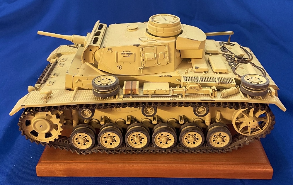
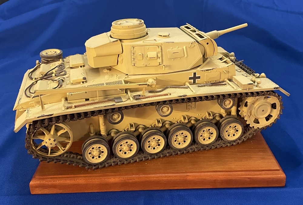
So, after careful review of both instruction sheets, one must decide which version to build. Either the J, L, or M. For this review, I have decided to build the Type J of the three. Pz.Rgt.7, 10 Pz.Div., Tunisia 1943. This version does not have the side armor (Schüzen) attached.
The complete build consists of:
- Lower hull and tracks
- Upper hull
- Turret and main gun
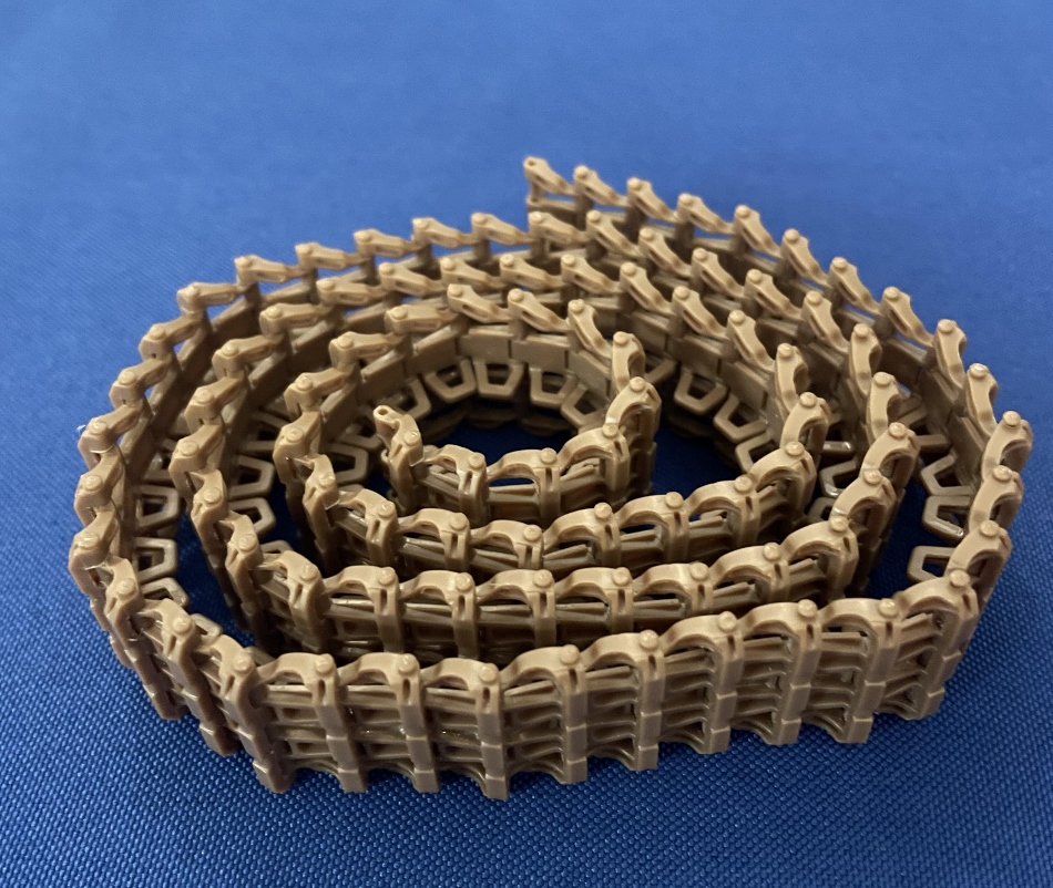
Note: As I find it tedious to put together individual track links, I decided to skip to Step 10 and start constructing the tracks over several days during the model build. Knowing I needed ninety-one links per side, I decided to construct 10-20 links per modeling session. The links are provided in pairs and need to be cut off the sprues and cleaned up. After a little sanding, the guide horns are glued on. Each link has a notch to accept the guide horn allowing proper placement. This was done for twenty links and set aside to dry. In the next modeling session, I followed the same procedures and constructed twenty more track links. Setting them aside after I had glued on the guide horns. From the day previous, it was time to start the track construction. The links snap together and are held in place with a guide pin. Careful installation of the pin is necessary. Any deviation from inserting straight in will result in a broken pin. Overall, each 10-link section takes less than 10 minutes to complete.
Get your mojo going because you have a total of 204 links to put together. Mind you each two links takes less than a minute. But, for me, it was a boring process, so I completed the tracks over several days.
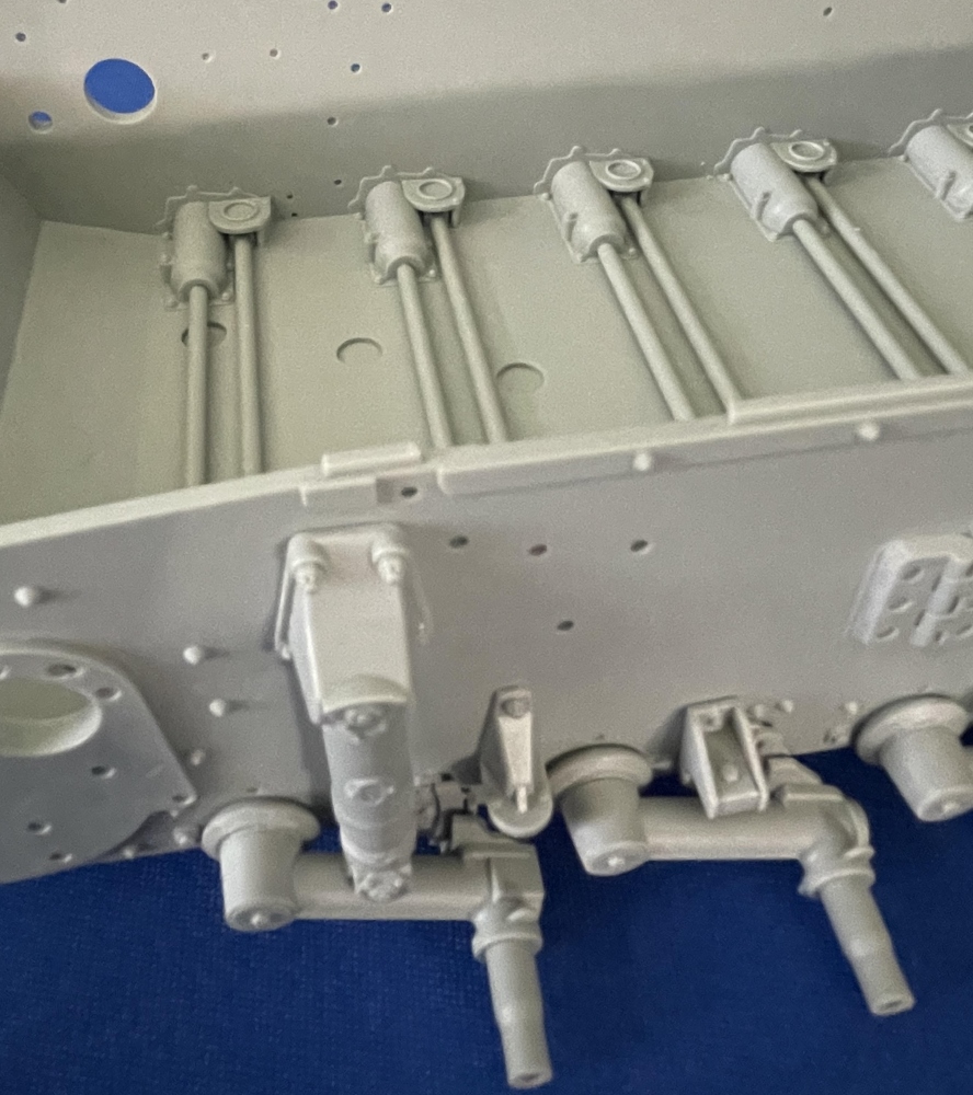
Steps 1-3 consist of building up the lower hull by adding a rear plate, crew hull access panels, and suspension rubber bump stop assemblies. Of interest is the rubber bump stops are molded on the black sprue (V). Did the manufacturer mold these out of black styrene to replicate rubber? Nevertheless, these need to be given a coat of flat black rubber paint. Exceptional detail is molded onto the bolt heads with the assemblies so far in the build. In Step 2 the construction of the workable torsion bars begins. The detail here is also excellent. The suspension damper-torsion bar assemblies in positions one and six consist of nine parts with the dampers molded as two pieces See parts E21 and E27. Unfortunately, this molding does not allow the torsion bars to flex as they do in two through five positions. To get around this, the modeler could use his scratch-building skills to construct workable dampers. With regard to installing the torsion bars in all the positions, the glue is only placed at the end of the torsion bar. Steps 2 and 3 are the same except one is for the left side and the other for the right side assemblies.
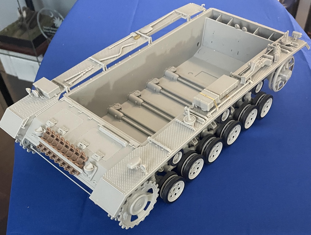
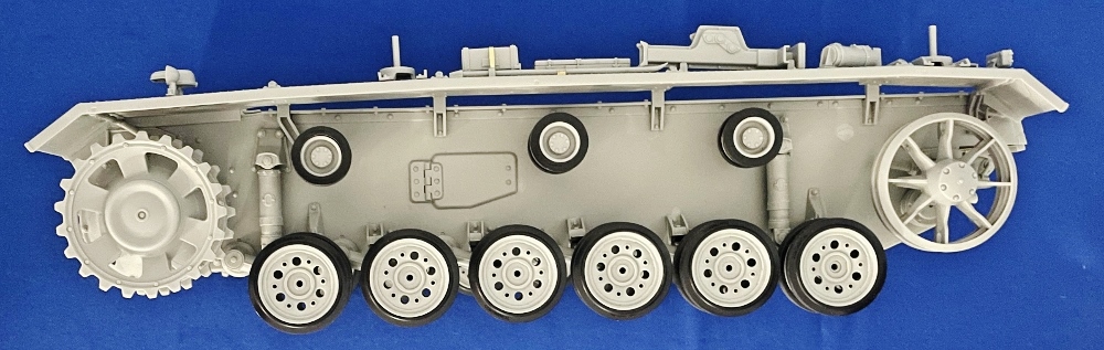
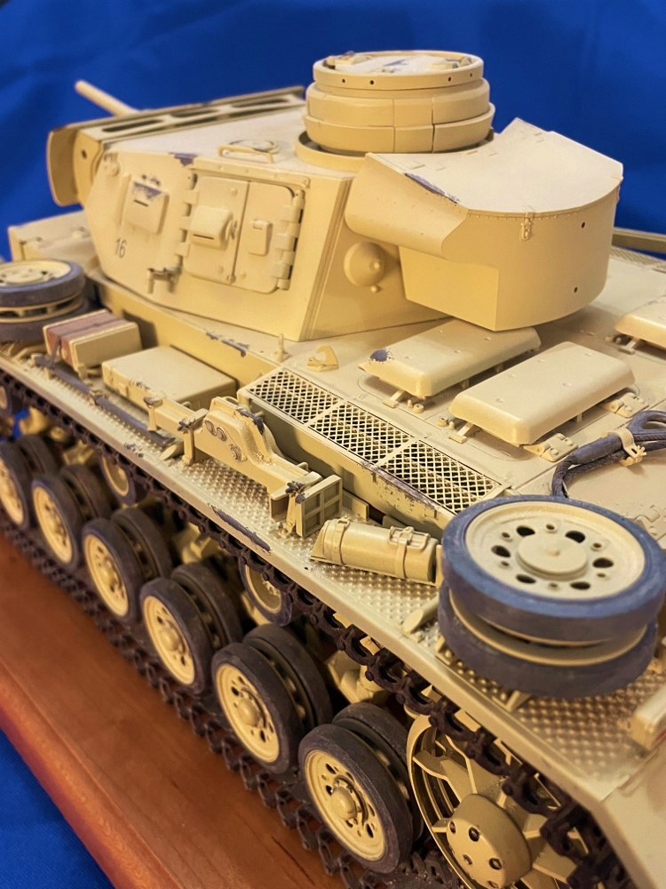
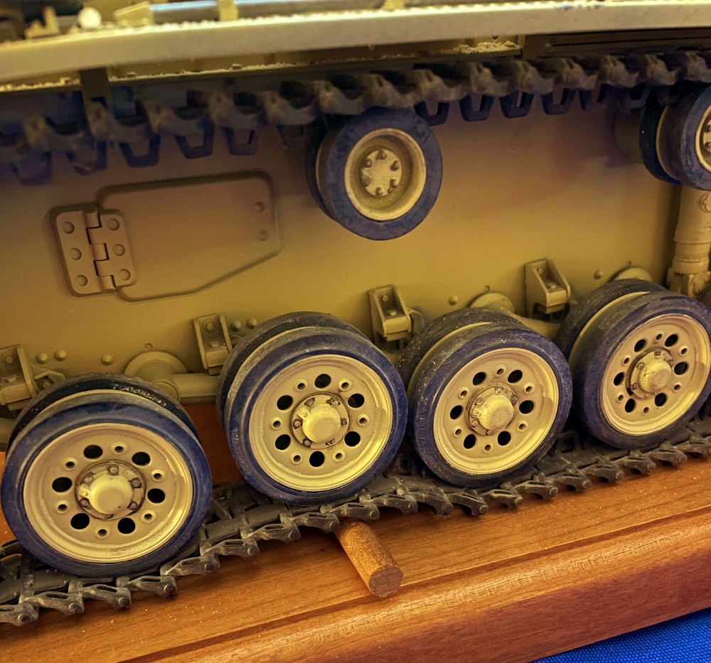
Steps 4-9 consist of building the twelve road wheels, two sprockets, two idler wheels, and six return rollers. The road wheels consist of four parts including one rubber axle cap. The road wheels are consistent in detail versus reference photos. Unfortunately, the separate tires have attachment points on the inside and on the outside of the tire. These will have to be sanded off and as a result, the entire molding seam will have to be sanded also. A few reference pictures show the molding seam in the center of the tire. To tone down the shininess on the rubber road wheels (Part V1), I dry brushed a mixture of Vallejo Pigments (Natural Iron Oxide, Light Slate Grey, Titanium White). The same goes for the return roller tires. In step 9 the idler assemblies are constructed. The detail is exceptional, but unfortunately, without modification, these cannot be made to adjust the tension. I do not foresee any issues with track tensioning. The wheels, sprockets, and return rollers were left off to allow for painting.
Steps 10-12 consist of adding the fender bracing and starting the track assembly. As I had started the track construction from the beginning, by the time I reached this step I had most of the tracks together. Exhausts are also constructed along with a piece of PE mesh along with a few covers under the hull. The rear plate is added along with an access panel.
Steps 13-21 consist of adding the glacis plate with access panels is constructed. These can be left open, but since there is no interior, I chose to close them. An extra length of tracks is built up for attachment and the PE tool clamps are made. These are workable and did require a little extra work on my part to articulate. In the end, these look great. Next up was adding the accessories to the fenders and finally adding to the lower hull. Attachment placement points made these an easy job.
As I was building the J model, I was able to skip to step 28.
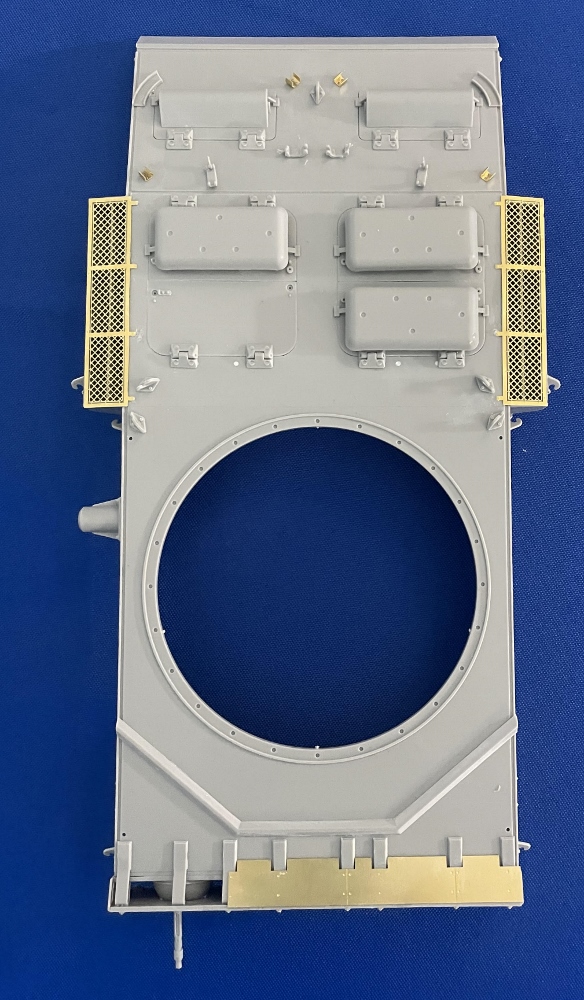
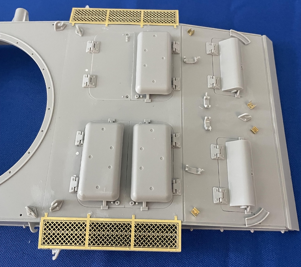
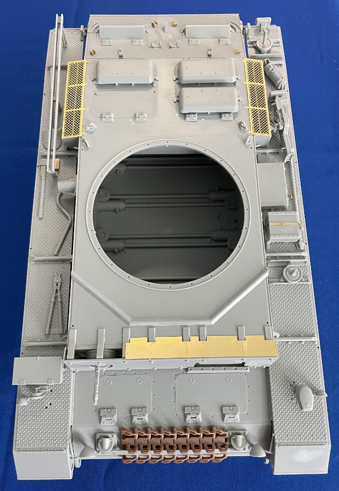
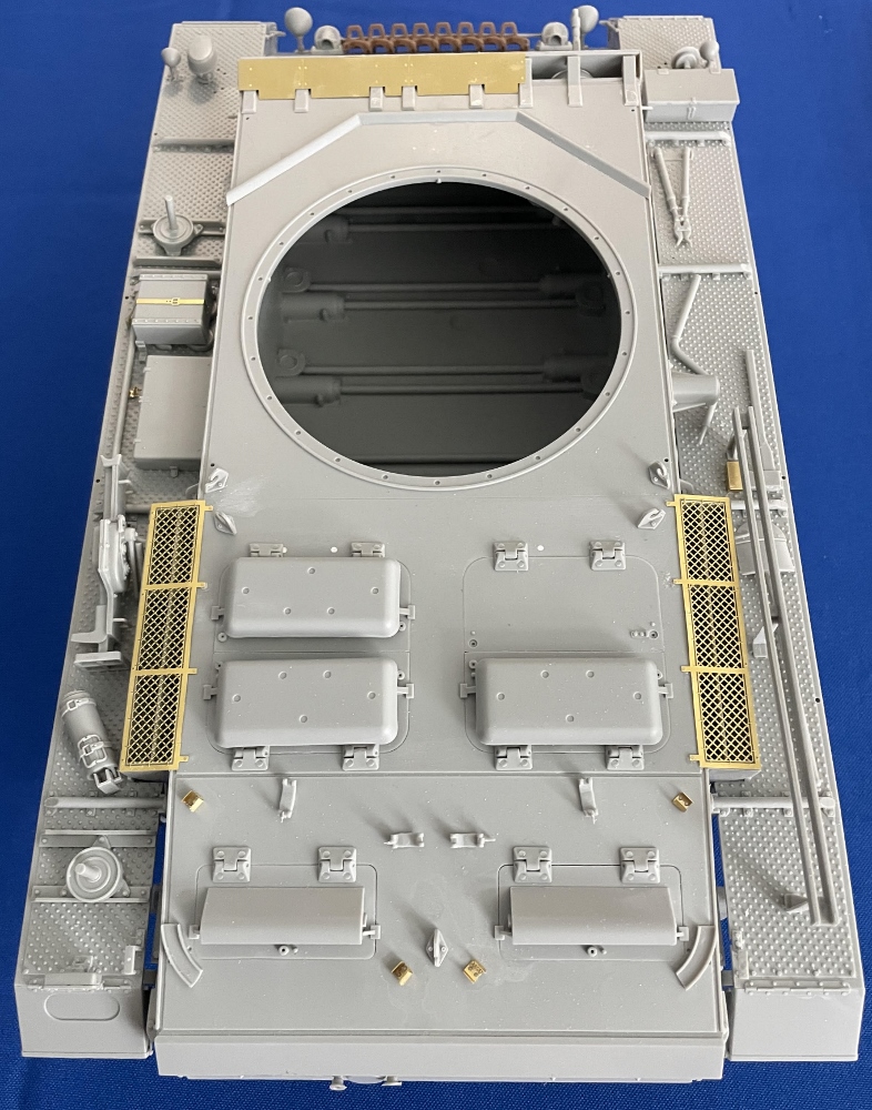
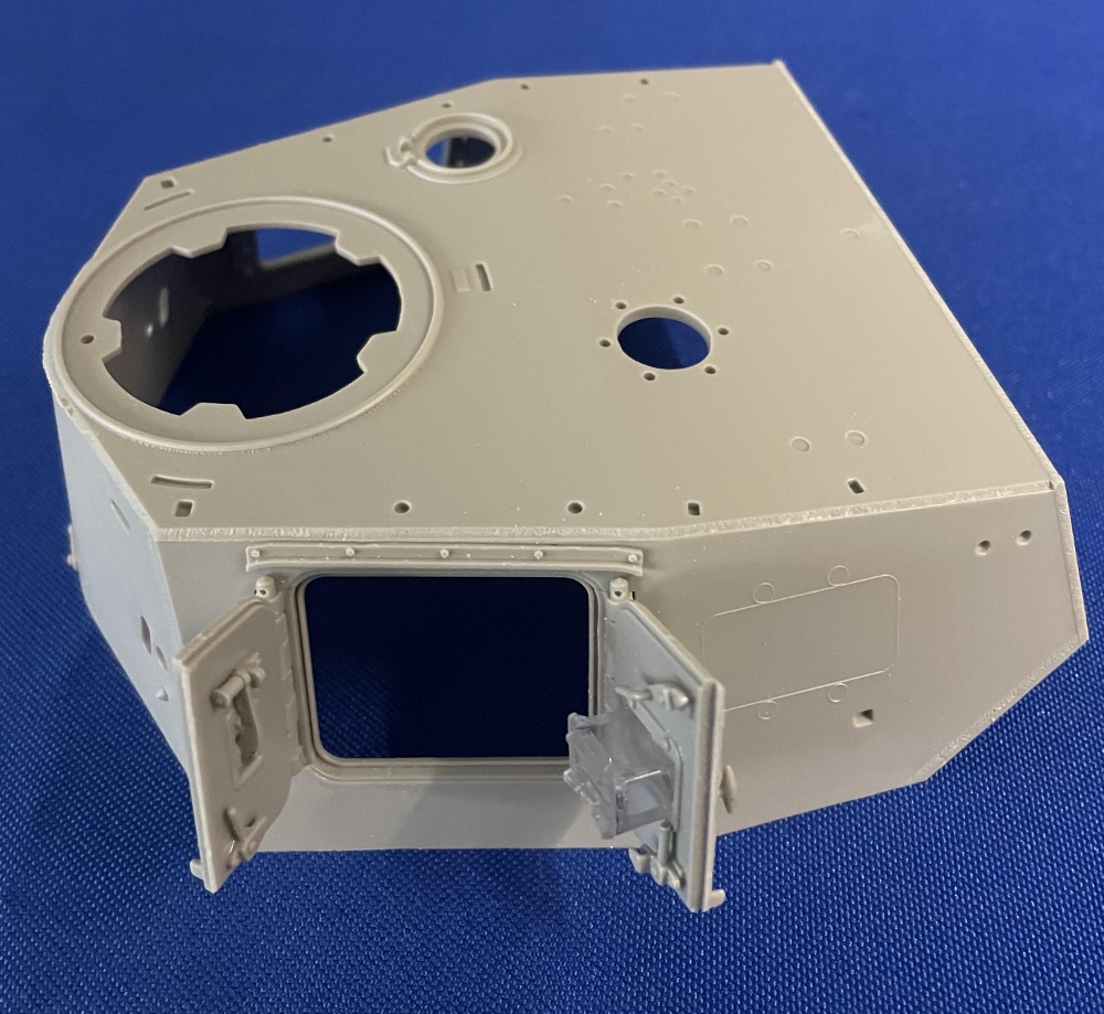
Steps 28-32 consist of drilling out the holes on the upper hull for hatch hinges. A few holes must be filled and sanded. In step 29 the side vision blocks are constructed. These can be closed or left open. The detail surrounding the vision ports is remarkable with clear prisms included. The ball-mounted machine gun is constructed in step 30. The detail and molding are excellent allowing the mount to move. Again, unless the hatches are left open, this detail will not be seen. In the next steps, the rest of the upper hull is finished by adding the front hull plate, PE on top, hatch covers, and hinges.
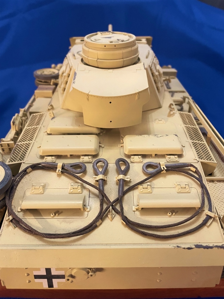
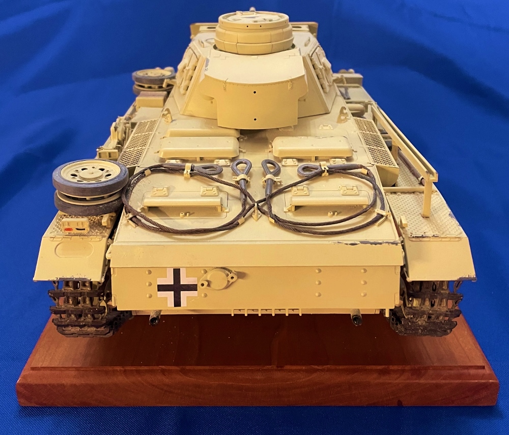
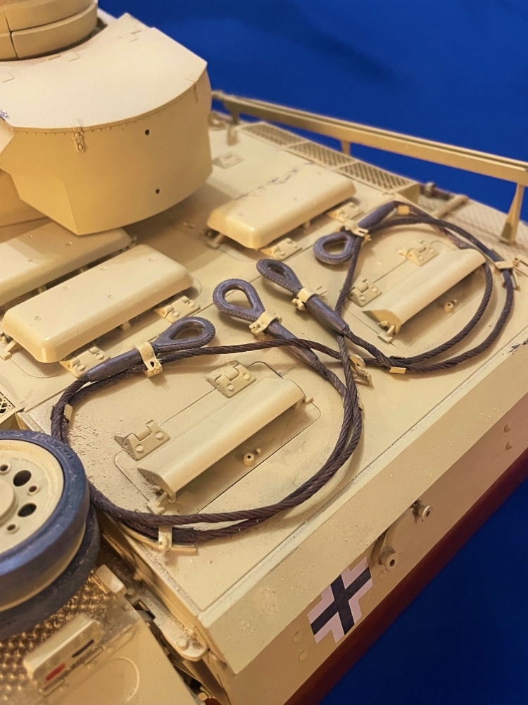
Step 33. This step consists of adding PE cable clamps and making two towing cables. To darken the copper cable, I used Birchwood Casey Super Blue. The styrene eyelets were first primed with Vallejo Red Brown Surface Primer and then a coat of Vallejo Metal Color Burn Iron. These were left until the model was complete before attachment.
Steps 34-36 consist of adding the engine air intakes on both sides with PE plates. However, in step 34 the instructions have you add the tow cable tie downs. These left off until the model was painted, and the tow cable was installed. Finally, in step 36 the antenna and mount are constructed. PE is added to the hinge assembly. A suggestion would be to leave off part X25 (deflection shield) until the turret is complete and test fitted to the hull. Part X25 may have to be moved for the turret to rotate properly. (This part I did not find out till I had already attached the shell shield).
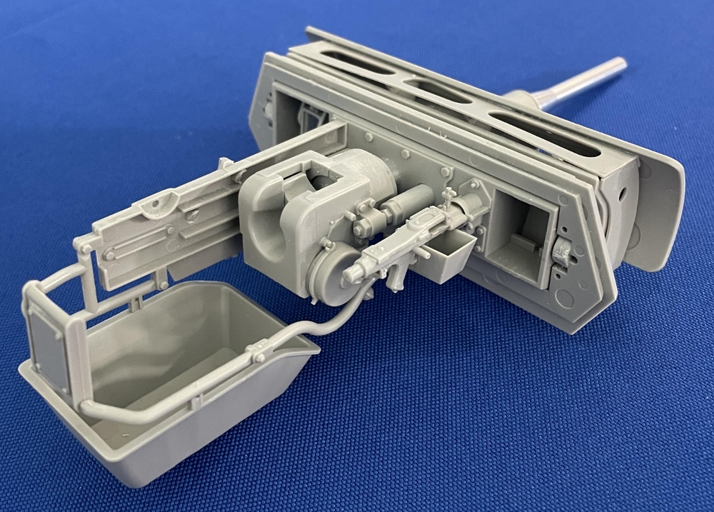
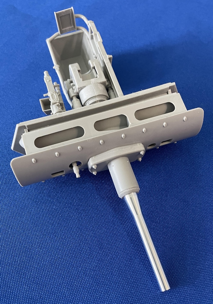
Steps 37-39 are the construction of the main gun and breech assembly. The slide detail on the MG 34 is excellent with the barrel open. I used the 5 cm KwK 38 L/42 metal gun barrel for the main gun supplied. The detail is so good it is a shame to close the turret up. Having no interior, this was not an option. I do foresee that in the future Gallery models will introduce the full interior kit.
Steps 40-45 start the assembly of the turret. In step 42 I did have an issue with attaching the side turret armor plate Part K-19. Minor changes had to be made for the part to fit properly. The other side’s equivalent part, K-20, fit without issues. This was in part due to an error I had made in previous steps. The turret cupola has detail inside as well as movable vision ports. These also can be displayed by the modeler open or closed. The turret ventilator port consists of four parts with a four-bladed fan nicely detailed. The turret hatch has detailed vision ports with covers and these also can be opened or closed.
Finally, Step 46 is the insertion of the turret onto the upper hull. Next on to painting.
Painting
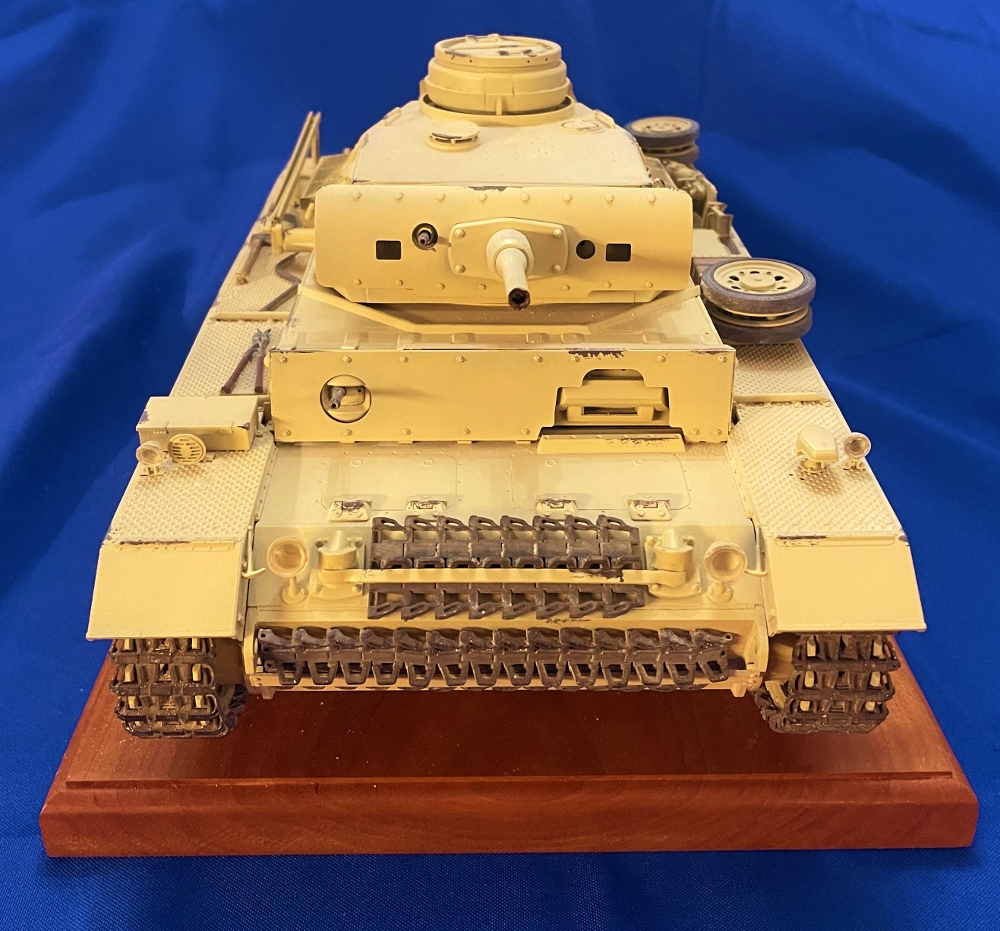
With the road wheels, return rollers, and tracks left off the vehicle, I primed the tank with Vallejo Desert Tan Surface Primer 73.613. After this dried, I applied three light coats of Ammo Mig RAL 8020 Gelbbraun 0016. The MG 34 barrel was hand brushed with Ammo Mig Gun Metal 045 and an application of a gun metal pigment using a Q-tip.
Using Vallejo Red Brown Primer as the main primer I then painted them with Ammo Mig Dark Tracks. A light brushing of Vallejo Desert Dust Pigment 73.121 and Ammo Mig North Africa Dust 3003 was applied before they were installed onto the vehicle.
Next came the application of the decals. I then applied a light coat of Model Master Clear Gloss to the areas where the decals would be applied. Letting twenty-four elapsed, I brushed on Micro Set followed by Micro Sol after I applied the decals. After six hours, I saw silvering had not appeared. The decals are thin and a bit finicky, so caution and patience are necessary when installing them.
Conclusion
This kit was a joy to build in part due to no major build issues to contend with and the fact the individual track links go together perfectly. As I at first was reluctant to start the process, I found dedicating time to each build session made a tedious process very enjoyable. Additionally, what I enjoyed about this build was that the parts almost clicked together without having to sand or drill. If I was supposed to insert a stub of a part into a hole, it snapped together. Add a little glue and “Wala”. The kit was molded with beautiful weld beads, and bolt heads, and the attention to detail by the manufacturer can be seen.
As this was my first large-scale building, I thoroughly enjoyed it. After completing each kit, I ask myself, “would I build this kit again?” Regarding this kit, my answer is “most certainly yes. My plan is to purchase another one of these, spend at least a year scratch building and use my 3D resin printer to build an interior. For these and many other reasons, I highly recommend this kit to anyone who wants to get into a large-scale building arena.
References used for this build and review include:
- Doyle, D. (2019). The Complete Guide to German armored vehicles: Panzers, Jagdpanzers, assault guns, antiaircraft, self-propelled artillery, armored wheeled and semi-tracked vehicles, and more. Skyhorse Publishing, Inc.
- Taylor, D., & Hayton, M. (2017). Panzer III: Panzerkampfwagen III Ausf A-N (SdKfz 141). Haynes Publishing.
- German Panzer Parts. (n.d.). Retrieved June 28, 2022, from http://www.questmasters.us/panzer_parts.html
Thanks to IPMS/USA and MRC for allowing me to review this kit.

Reviewer Bio
Phillip Cavender

Phil Cavender, IPMS/USA #50085, is a retired pharmacist from the Veterans Administration, having retired in 2011. While he explored model car building as a child, it wasn’t until 2015 that he rediscovered plastic scale modeling. His renewed interest emerged while researching his father’s military history, which led him to a local hobby shop. There, he met a former UK military tanker who reignited his passion for the hobby. After relocating to Myrtle Beach, Phil teamed up with six skilled modelers to co-found the Grand Strand Scale Modelers chapter of IPMS/USA. He now focuses on building armor models in scales from 1/35th to 1/16th.
Comments
Scale
Correct scale is 1/16th.
Fixed
Fixed
Add new comment
This site is protected by reCAPTCHA and the Google Privacy Policy and Terms of Service apply.
Similar Reviews