
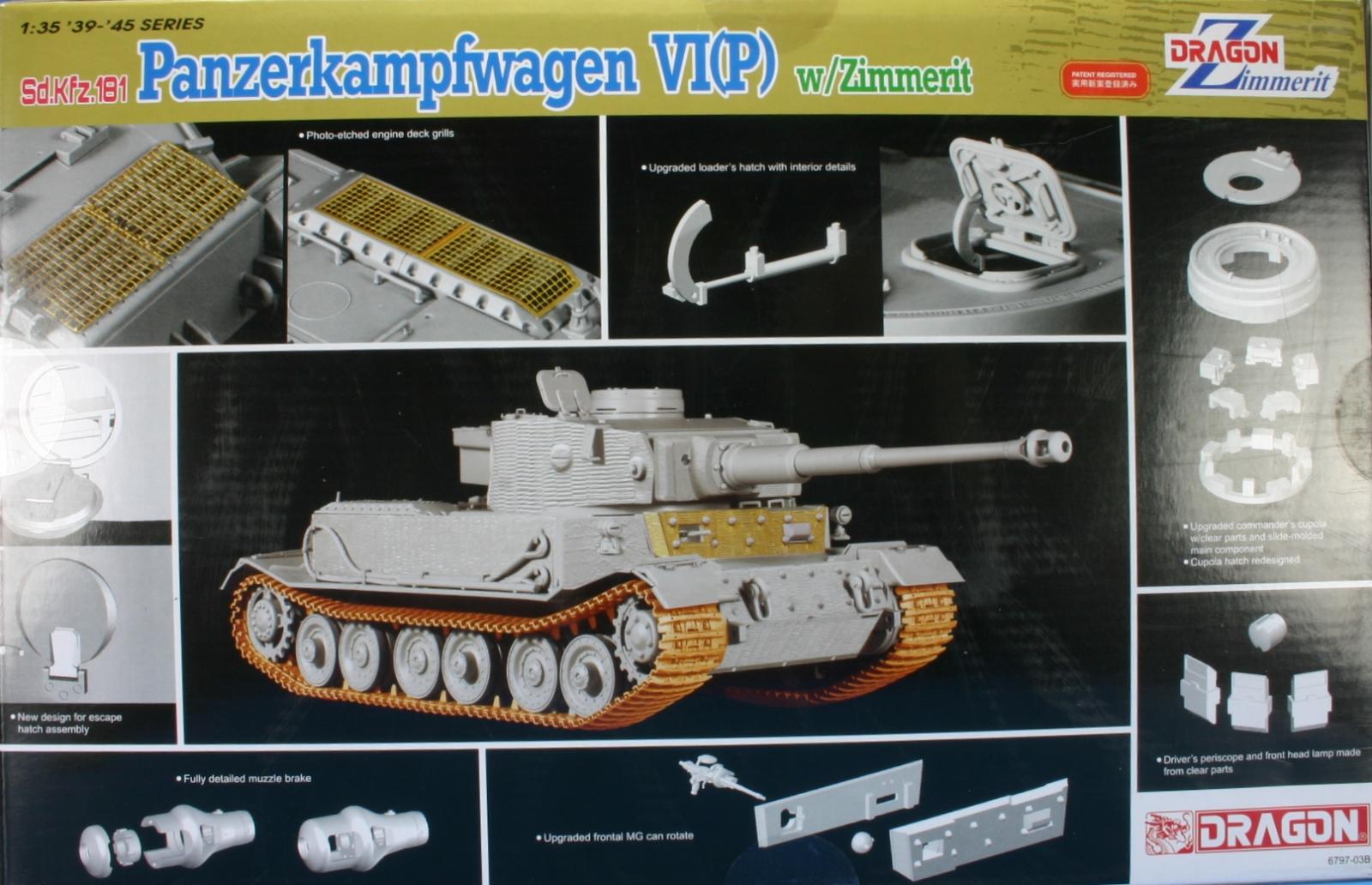
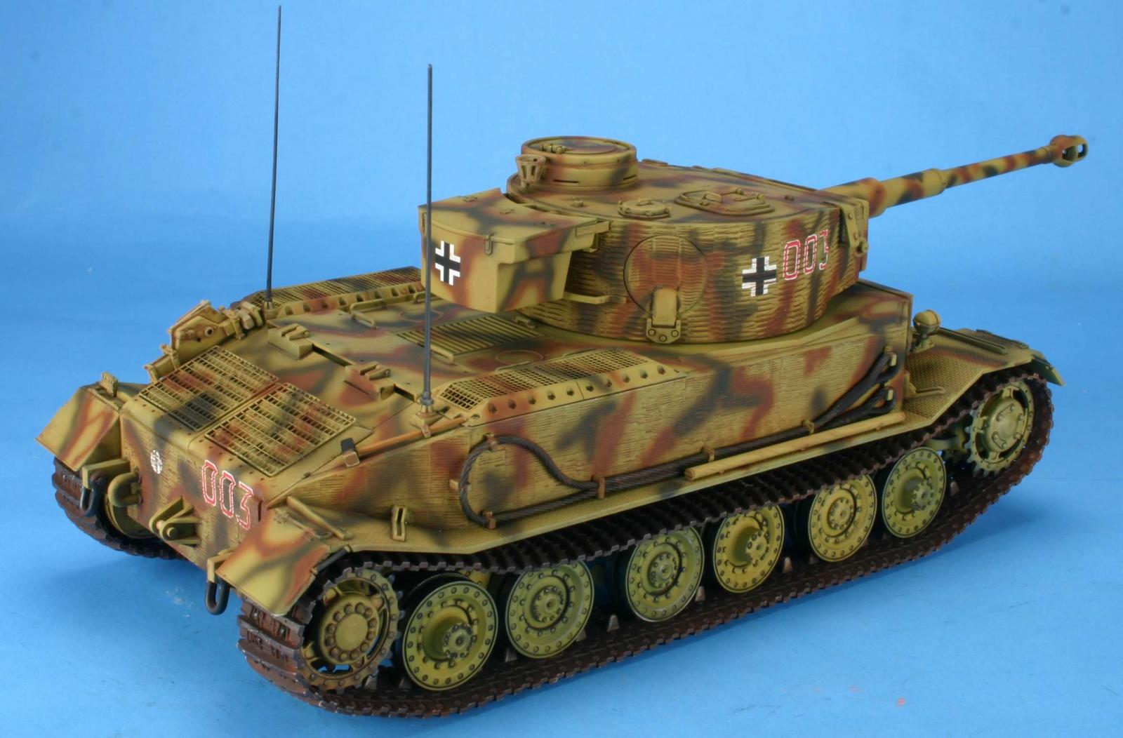
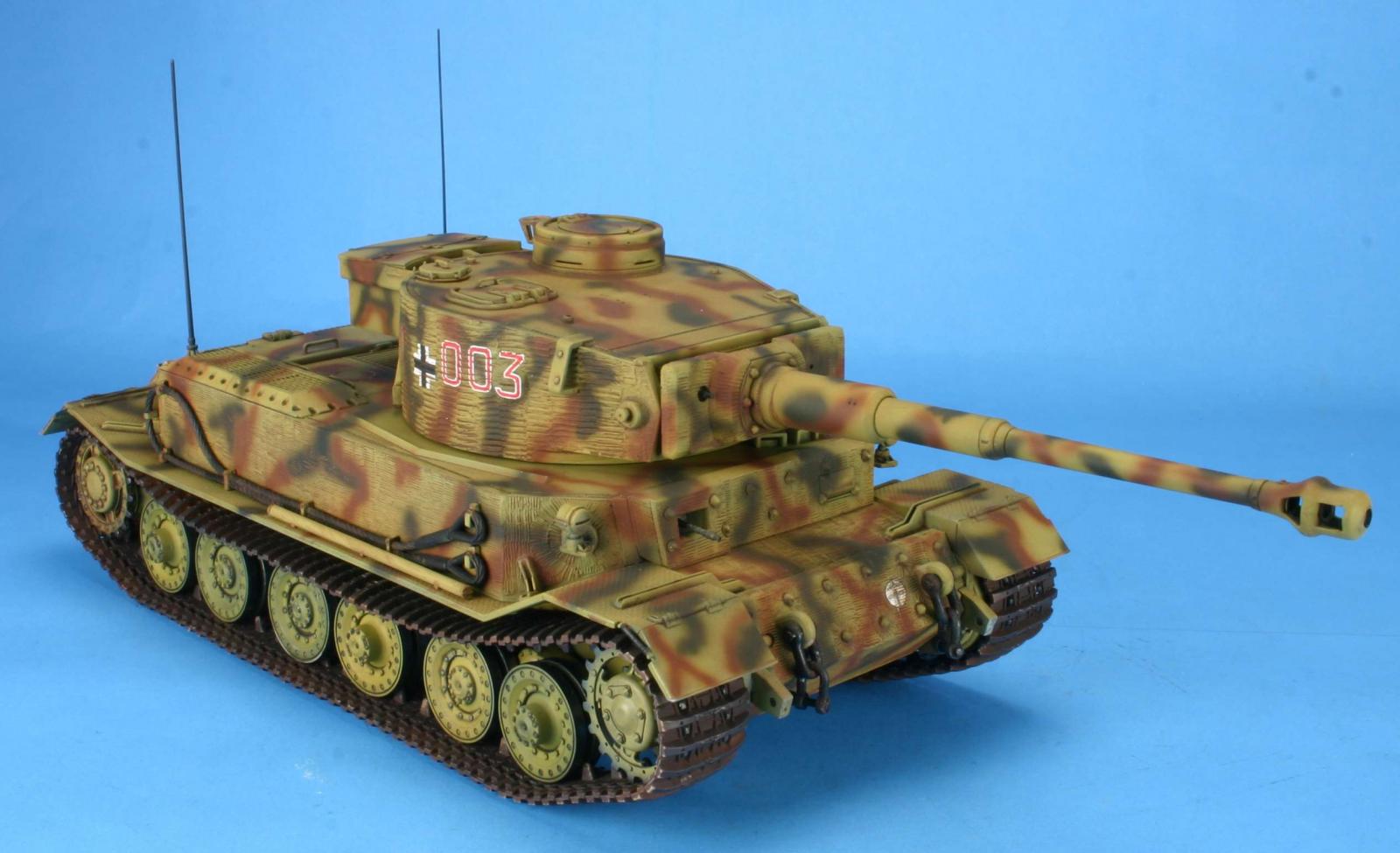
Panzerkampfwagen VI(P) w/Zimmerit
This is a multimedia kit comprised of 470+ styrene parts on 24 sprues, DS tracks, two small photo etched fret, decals and the set of instructions that need to be reviewed very carefully before gluing any parts together. The DS tracks have no shape or sag. I have tried to introduce this shape by using the Hobby Trax forms. Generally I was successful, but if your model is to be shown in a contest, I suggest that you replace the tracks with individual links (magic tracks or Fruil).
Most Dragon models today are a collection of old sprues and new sprues added to create a new kit variant. In this case, Dragon has done so and you will have some sprues with the same letter but are called out by the color (see Sprues Blue A & L).
- Step 1. This step is the assembly of the drive sprockets, and road wheels. There are no problems here other than the removal of the mold line which is noticeable on the road wheels.
- Step 2 & 3. This step is builds the torsion bar suspension road wheel arms. My set had an alignment issue with the pins on parts F7 and F12. If you don’t clip them off, you will have a very noticeable seam line.
- Step 4. This step adds the torsion bar suspension arms. If these arms were built as described in ste 2 & 3, they will be moveable and allow you to do some uneven ground under the treads.
- Step 5 & 6. This step adds the running gear to the hull chassis. No choices here. I left them off at this time for ease of painting. The idler wheel can be positioned to adjust the track sag, so I did not attach at this time. I will do that when the tracks are mounted.
- Step 6. This step attaches the rear panel that has the muffler that was attached in step 4. The instruction photo shows a mounted smoke candle, but it is not called out and do not appear to be on any sprue. Just ignore this part.
- Step 7. This step adds the front deck M3, but never shows part M2 being installed. This step also shows removing conical pin at the rear (4 on each side). This will take some care as the zimmerit is right up to the pins and you will need to scrap some new zimmerit lines into where the pins were removed.
- Step 8. This step adds the rear late and the towing brackets. You are to drill out locating holes for the center tow shackle brackets. The left set of holes are not far enough apart for the pins of part A3. I ended up by cutting off the top pin as the bottom hole was even with the hole on the right side.
- Step 9. This step builds the front bolt on armor plate and attaches to the chassis. You need to make sure the fit is good as there should not be any gaps.
- Step 10. This step builds the internal machine gun. There is a lot of detail on the machine gun, but you will not be able to see any of it other than the barrel that extends outside. The front plate is listed as A16, it should be M10. This is where you add the Photo Etch zimmerit to the plate. The fit is pretty good, but dry fit until you are happy as when you apply the super glue you will not be able to remove the PE with seriously damaging it.
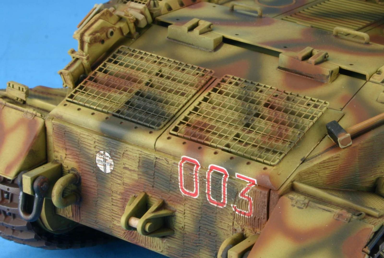
- Step 11. This step adds the front 3 periscopes to the top deck. Insert these periscopes before you attach the deck to the chassis. The top deck and the two fenders are added at this time. The underside of the fenders will be visible so you will need to take some time to remove the knock out pin marks and the locating holes that go all the way thru. You will need to drill out the locating holes for parts H5 & H6 (installed in step 14), this is not called out in the instructions. Rear fender flaps are not zimmerited. They have zimmerit in the reference photos found in Panzer Tracts. If you want to match the only tank to make it into combat, you will need to add your own zimmerit.
- Steps 12 & 13. These two steps build the air intake frames. The photo etch screen do not fit into the frames. I spent a lot of time filing down the PE and scraping out the frame till I got them to fit.
- Step 14. This step adds a lot of little parts all over the fenders and chassis. Vision port covers M8 show a locating plate for the headlights in the instructions; however they are not present on the part. The parts A37 and A38 fender brackets are added, but there are not locating holes in the fenders or locating lines on the chassis. Here you will have to eyeball and guess where they should be placed. I left off the headlights till late as these can be snapped off during handling. When attaching H5 & H6 make sure you test fit before gluing. One way leaves a large gap between the bracket and the front deck, the other way is correct. I painted the pioneer tools and tow cables off the model and added them after the paint scheme has been done.
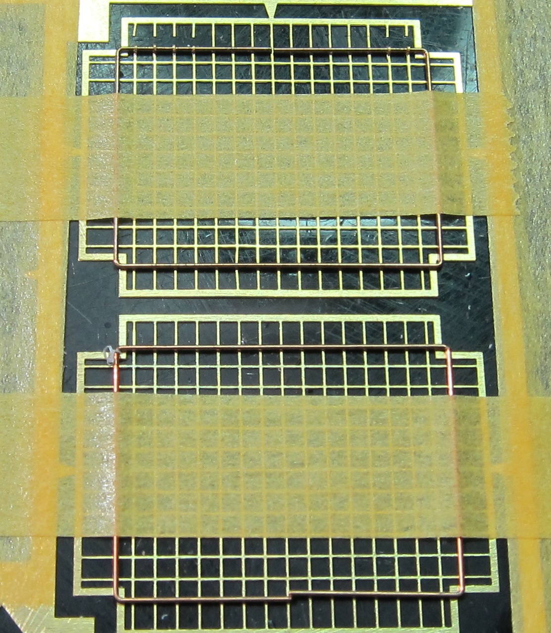
- Step 15. This step builds the jack and the Photo-Etch screens for part L10. The Photo-Etch screen instructions call for 8 metal pins to be clipped from the included brass rod. I chose to use plastic rod to create the 8 1.5mm pins and glue them to part L10. The creation of the screens themselves requires some planning before you start. I ended up by not clipping the screens off of the fret. I then taped the fret, good face down, to a cutting board. I then lined up the preformed brass rod on top of the PE screen and taped it down. (See photo) I then clipped one side of the screens connection point to the fret. I then rolled the connection point around the rod and repeated till one side was complete. I then did the same to the opposite side. When those two sides were done, I removed the tape holding the preformed rod down (it is now held in place by the screen itself) and did the other two side. Repeat for the other screen. Parts A7 and K4 are the radio antenna mounts. The kit only supplies the base and the short mounting rod (A6 & K5), you want to mount and antenna, you will have to supply it from the spares box or the aftermarket antennas. Parts A35 & A36 have no location holes or locating marks. You will have to eyeball the location. Just make sure the match in location on each side.
- Steps16 & 17. This step builds the barrel and gun mount. Do part A9 at the end, as the barrel will not fit parts T12, C19, and C25 with part A9 installed on the end of the barrel.
- Step 18 & 19. This step builds the basic turret configuration. The loaders hatch hinge C37 will not fit properly unless you clip off the mounting location molded into the turret H15. This hatch and the gunners hatch and be shown in the open position. However, the interior of the turret is rather sparse other than the gun. Make sure gun mounts A14 & A15 are completely down in the locating slot, as if not, the turret top will not sit flush with the turret sides.
- Step 20. This step completes the commander’s turret. It can be shown open or closed. As stated before, due to the sparse interior you may want to show this closed. You may also want to insert a commander in this hatch, but there is not a standing point for him in the turret.
- Step 21 & 22. This step completes the turret by adding a photo etch spare track rack MA2. The kit does not supply any spare tracks, if you want to display any tracks, you will have to get them from the spares bin.
Accuracy
The drawings found in the references listed below show the kit to be basically accurate. Since I’m not a rivet counter I don’t go beyond that. I model for fun.
Molding
I found the molding to be clean, with no sink marks and few ejector pin marks. The mold seams were easily removed and I saw no flash. Dragon makes extensive use of the pin nodes to keep ejector pin marks on the parts to a minimum. However, you will need to handle the removal and clean up of the parts with care.
Instructions
As with all Dragon’s instructions, read them carefully and plan what you want to do ahead of construction. Check the fit over and over and over again to make sure that all items fit together.
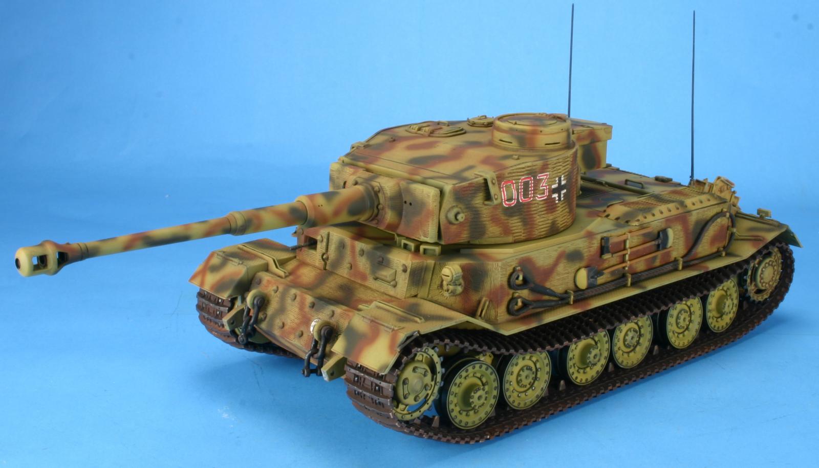
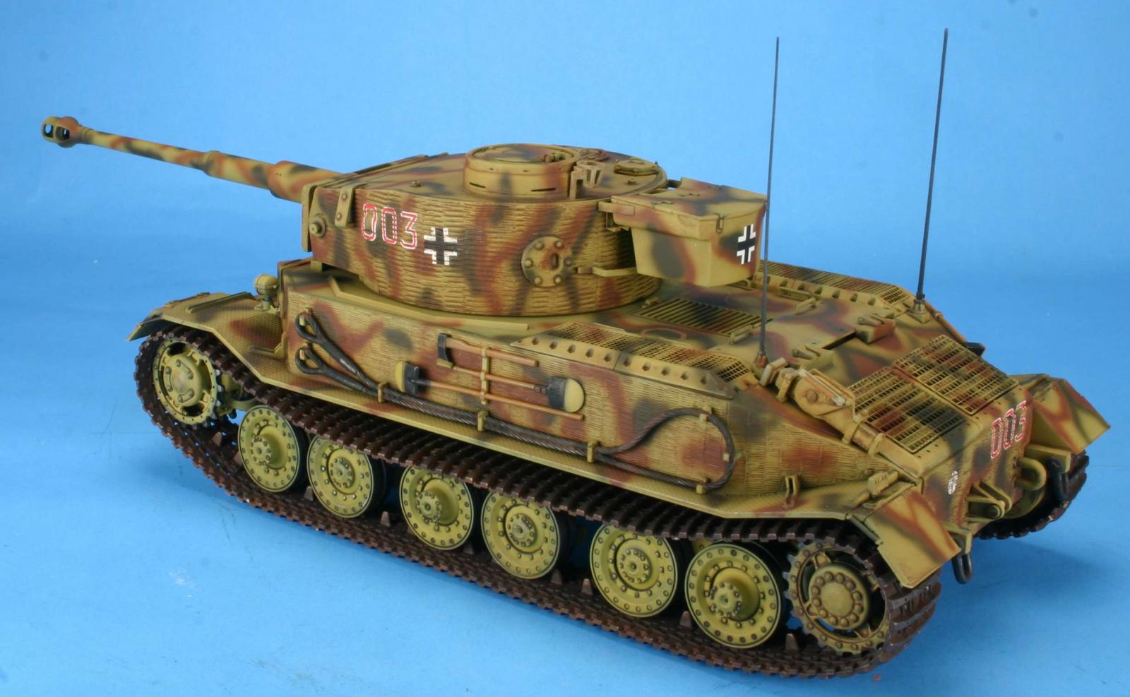
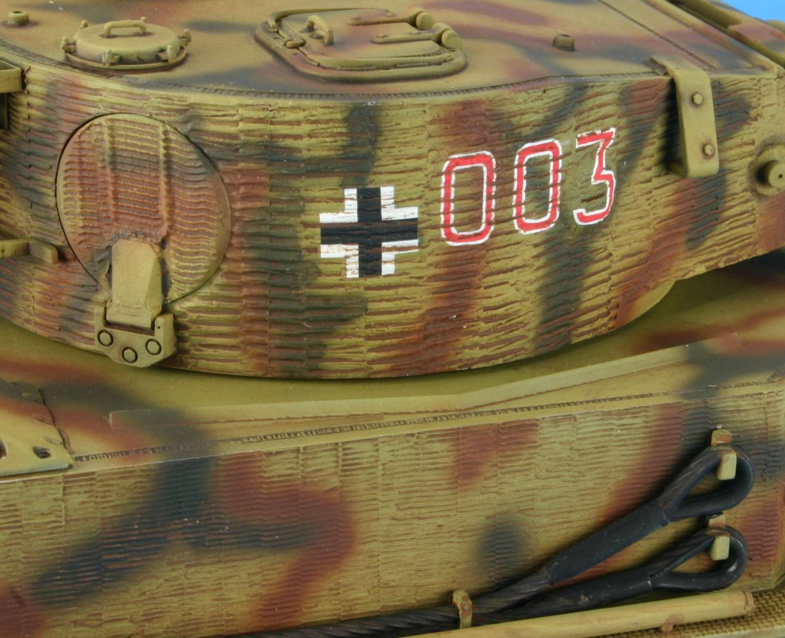
Painting and Decals
The color call outs are for Testors Model Master enamel and Gunze paints. I continue to see a weakness in the painting instructions from all kit makers. Instructions for the small parts like the pioneer tools and travel lights are never listed or shown. Here you have to guess or mimic what someone else has done. There is only one paint scheme listed S.Pz.Jg.Abt 653. Eastern Front 1944 The decals are by Cartograf and are up to their usual high standards.
Conclusion
his is a well engineered and molded model. If you make sure that the instructions are correct, the model goes together very well. It is a good mix of styrene and Photo-etch. I can recommend this kit to all WWII modelers.
References for this variant are included in the following books:
- Panzerkampfwagen VI P Sd Kfz 181 by Thomas L. Jentz and Hilary L. Doyle Published by Darlington Productions, Inc ISBN 1-892848-03-01
- Tiger & King Tiger Tanks and their variants by Walter J. Spielberger English version published by Haynes Publishing Group 1991.
Of course, there are others available.
Thanks to Dragon for the review sample and IPMS/USA for the review space.
This model can be found at most hobby shops, online hobby shops and at www.dragonusaonline.com.

Comments
Add new comment
This site is protected by reCAPTCHA and the Google Privacy Policy and Terms of Service apply.
Similar Reviews