
Panzerkampfwagen T34-747[r]
Dragon’s latest release of the T-34 is a little bit of a different take. This kit represents a Beutepanzer (captured tank in German service) T-34/76 STZ Model 1942. The Germans captured hundreds of Russian tanks but the actual number of T-34s in service appears to be very low. The Encyclopedia of German Tanks of World War Two has this figure listed as 50 prior to May 31, 1943. Of the 50, only 17 were noted as serviceable.
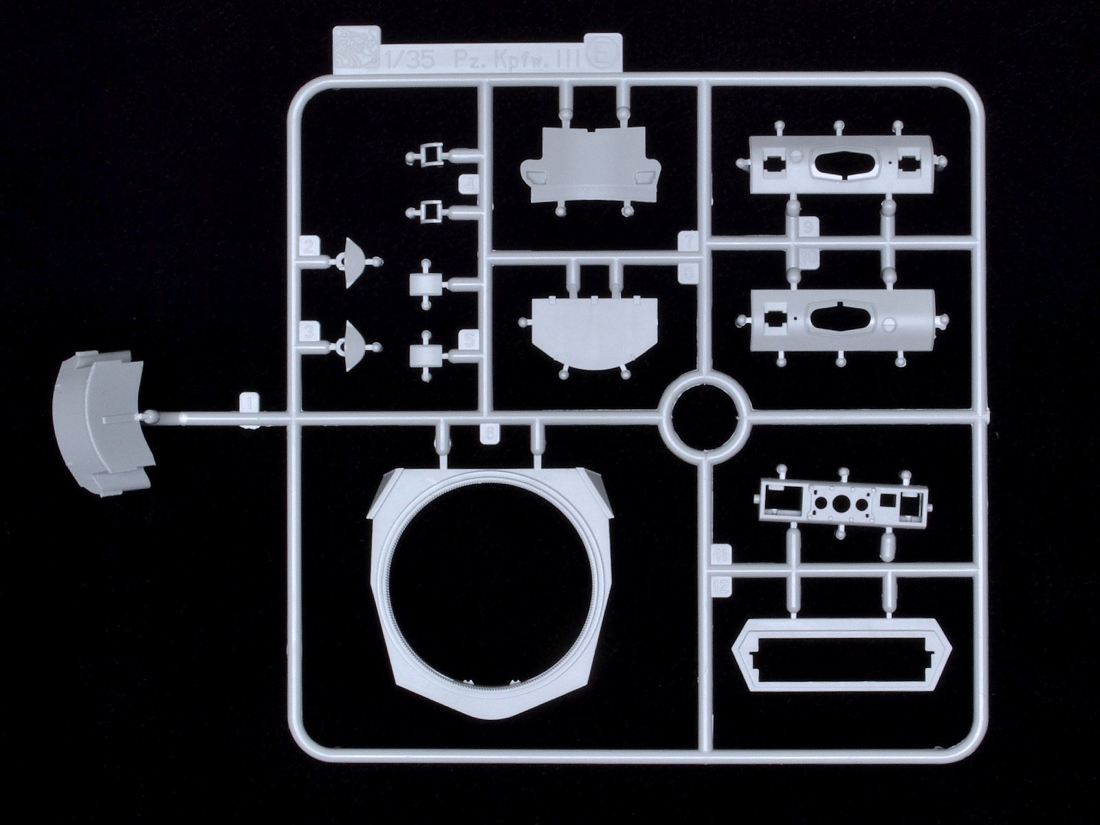
This kit is largely based on Dragon/Cyber Hobby’s 6388 T-34/76 STZ Model 1942. It has the chiseled shaped mantle, angled turret cheeks, interlocked welded upper hull, and cast steel wheels. It also includes a PzIII turret stowage box.
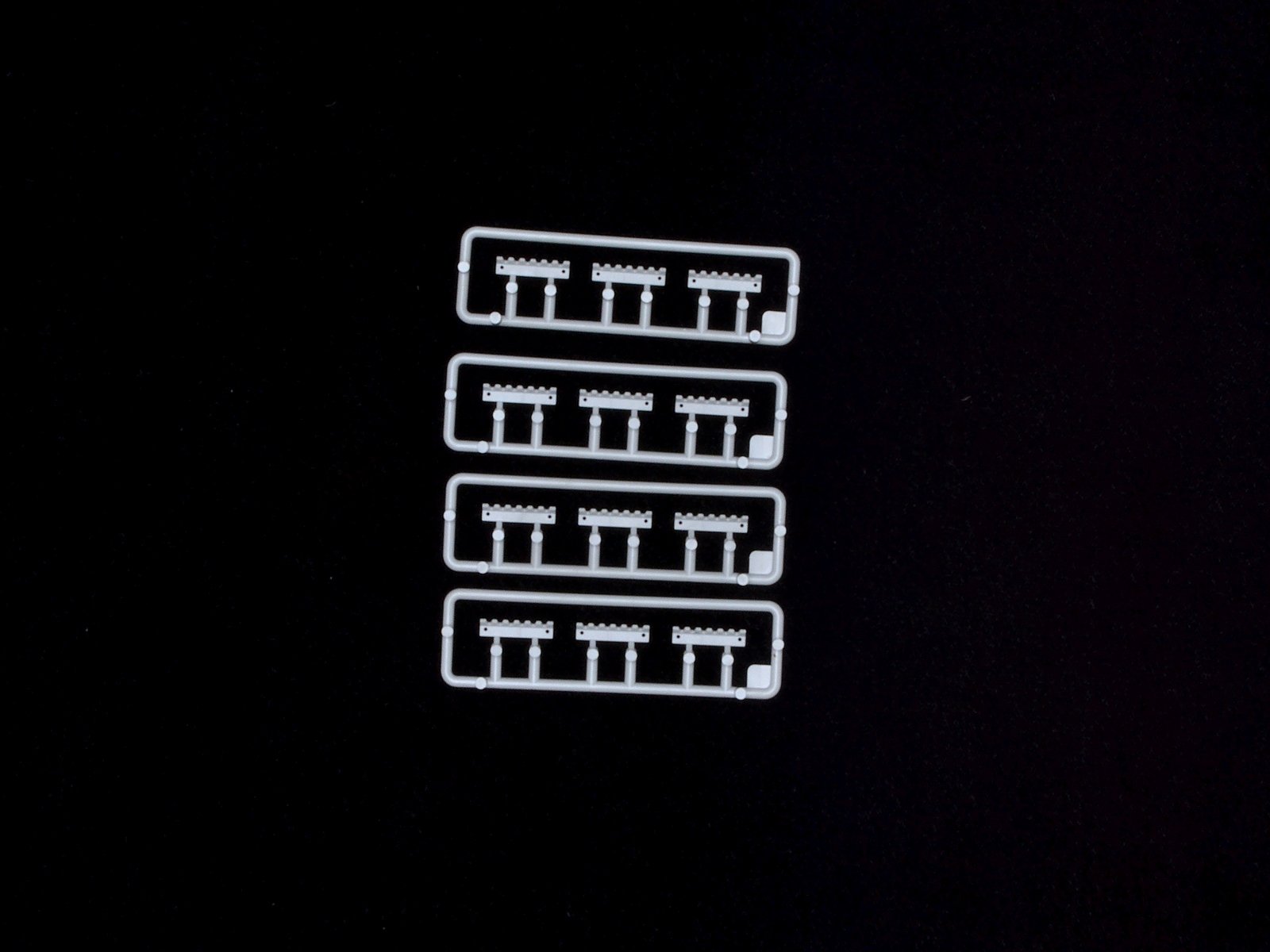
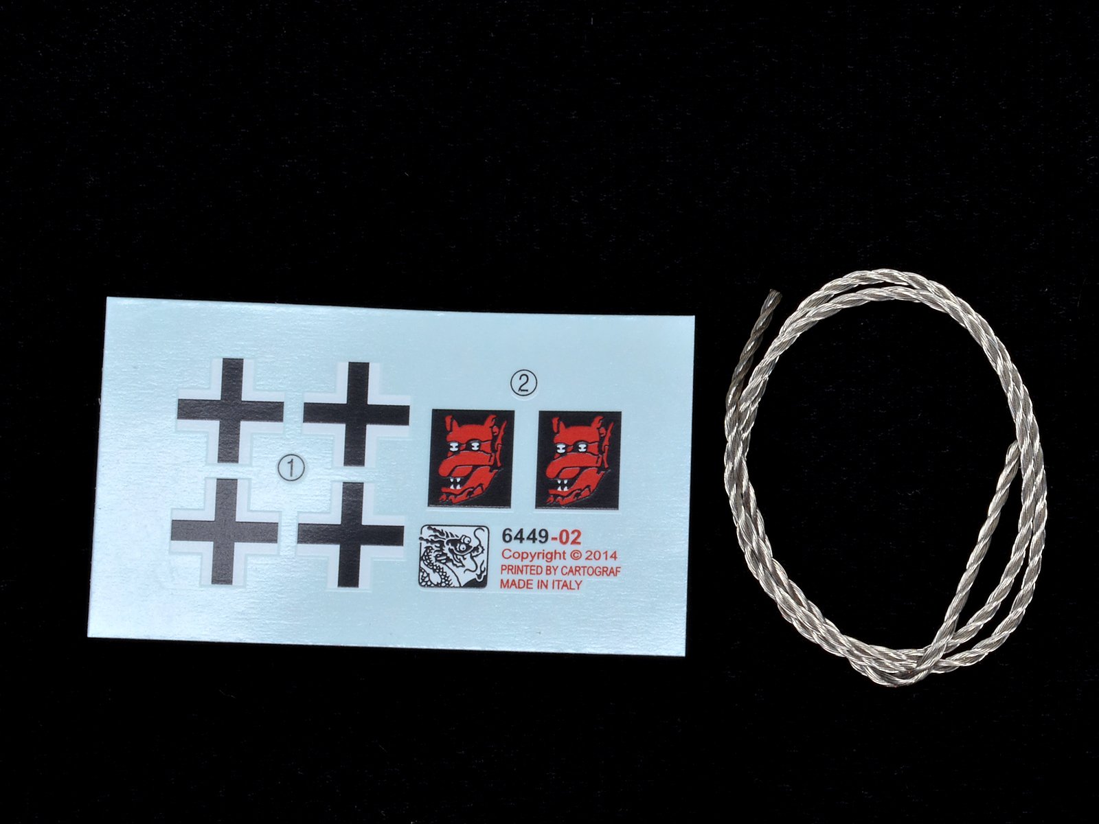
The box is stuffed with sprues, two bags of Magic Track for the A&B sections of track, a small sheet of etched brass (though not as involved as the 6388 release), and a length of braided steel wire for the tow cable. The kit include numerous extras including two extra turrets, two extra front glacis, two extra barrels, multiple turret hatch options, bolted rear hatch and numerous smaller details not used in this kit. There are so many parts that look similar that it will be important to verify the part number before you clip the sprue. I learned the hard way a couple of times.
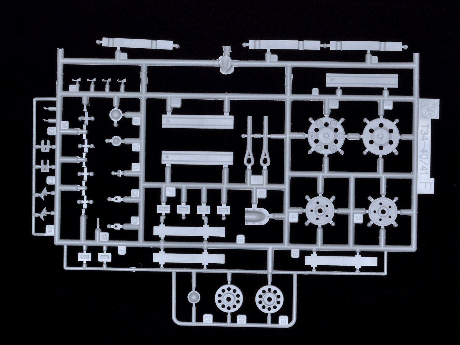
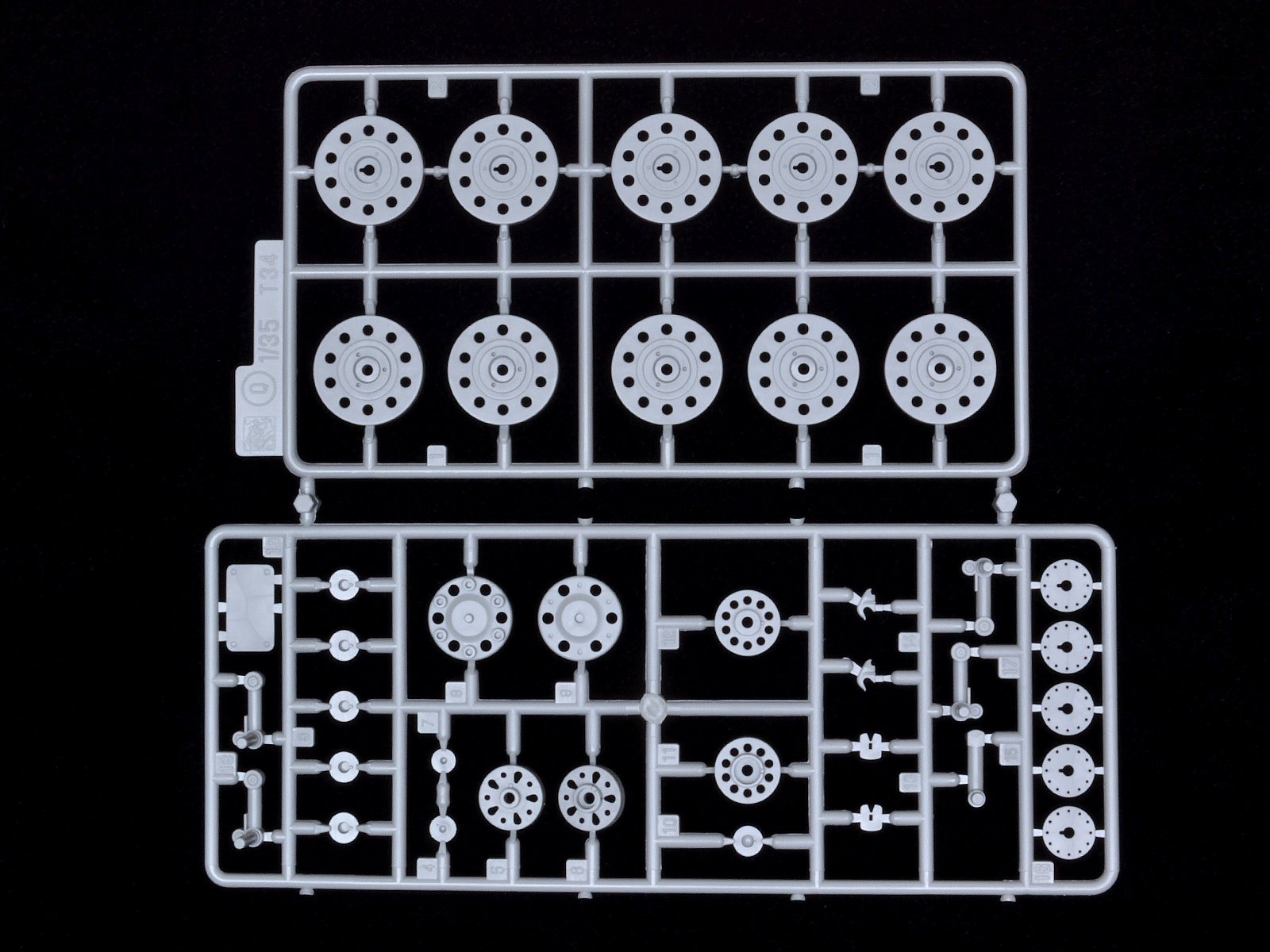
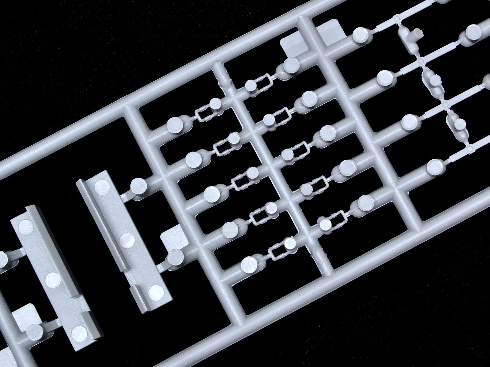
Step 1
Like most Dragon kits, assembly begins with the road wheels and drive components. The road wheels are the cast steel type with internal rubber bushing, so if you don’t care for painting rubber road wheels, this is your kit.
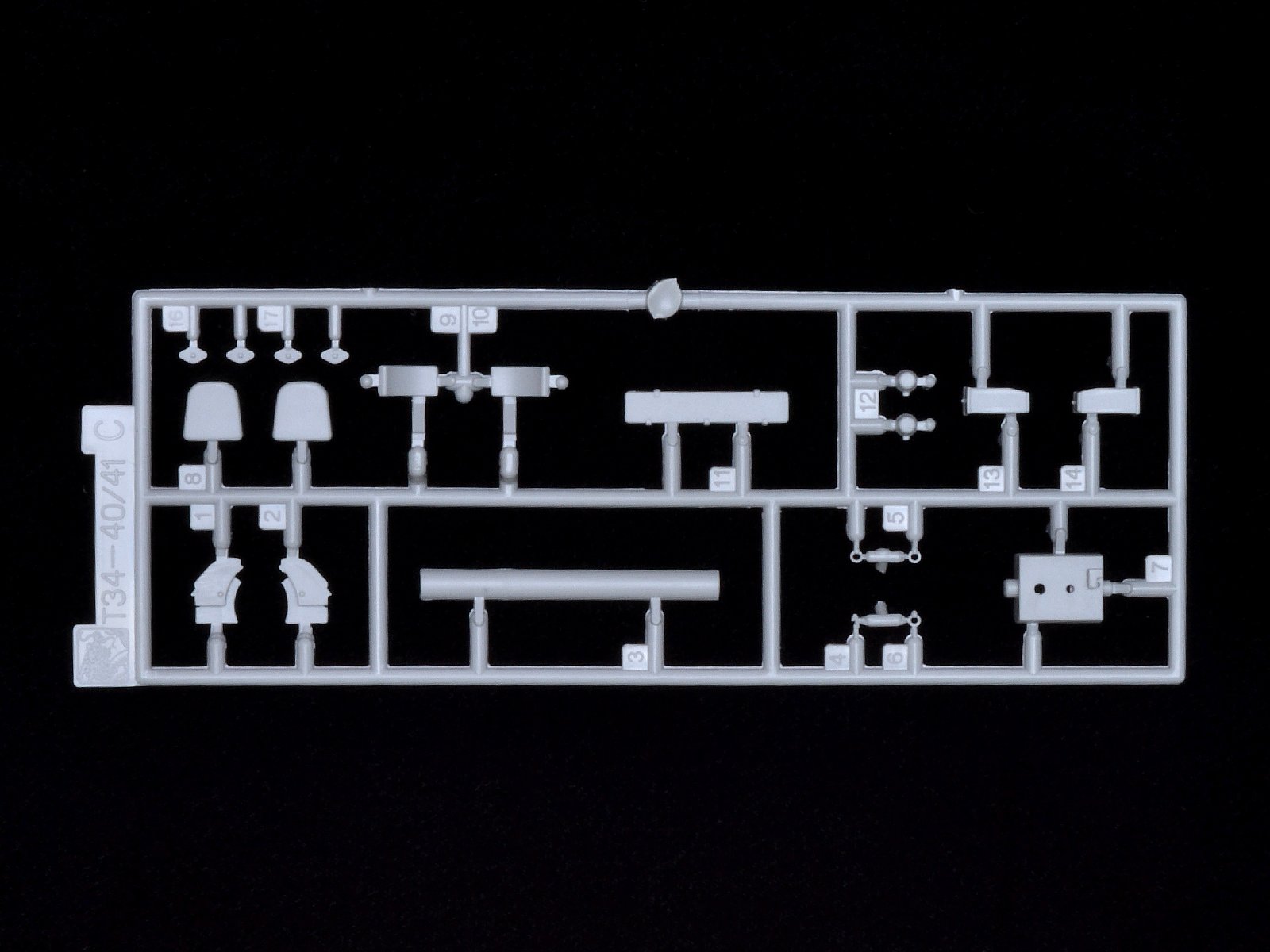
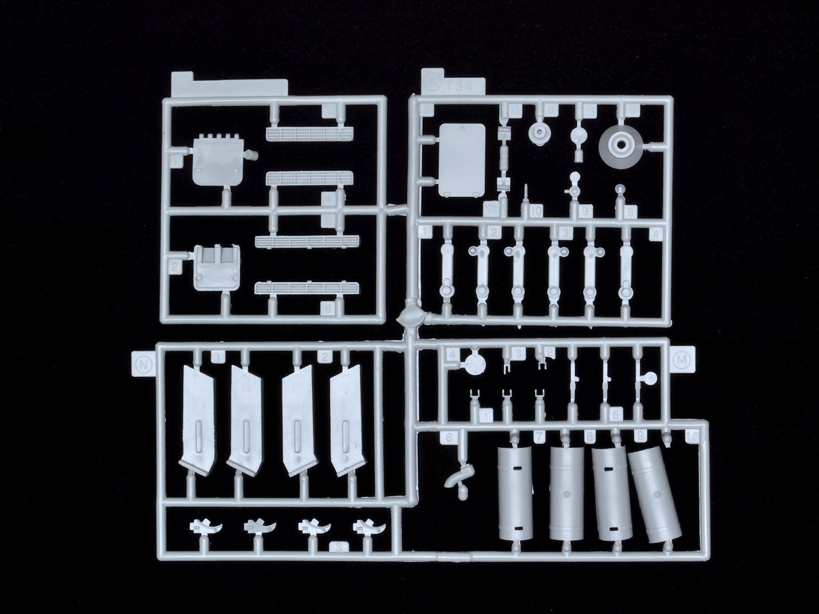
Steps 2 thru 4
These steps deal with assembling the running gear to the lower hull pan. Some of the parts are starting to show their age with the older molds. Parts N1 and N2 don’t seem to have the same finesse as more recent releases. But these are mostly interior pieces and most of this won’t be seen so it really is a mute point.
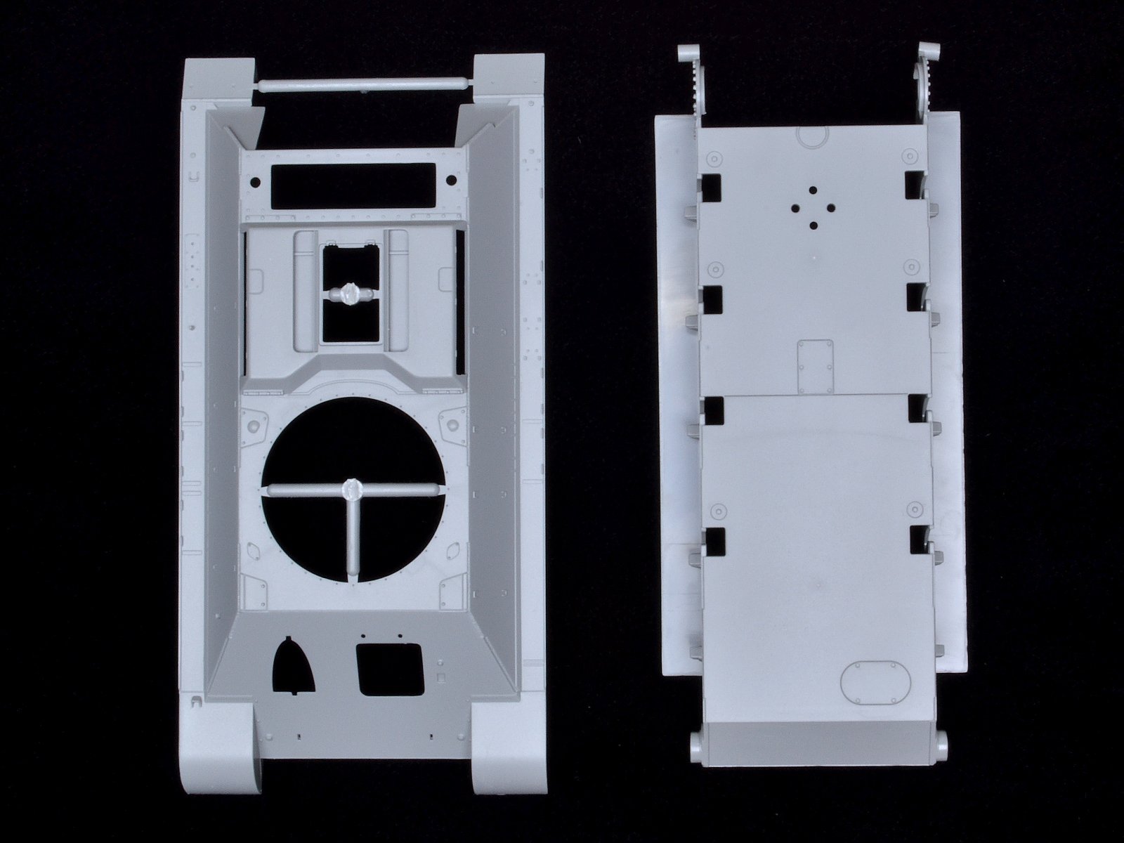
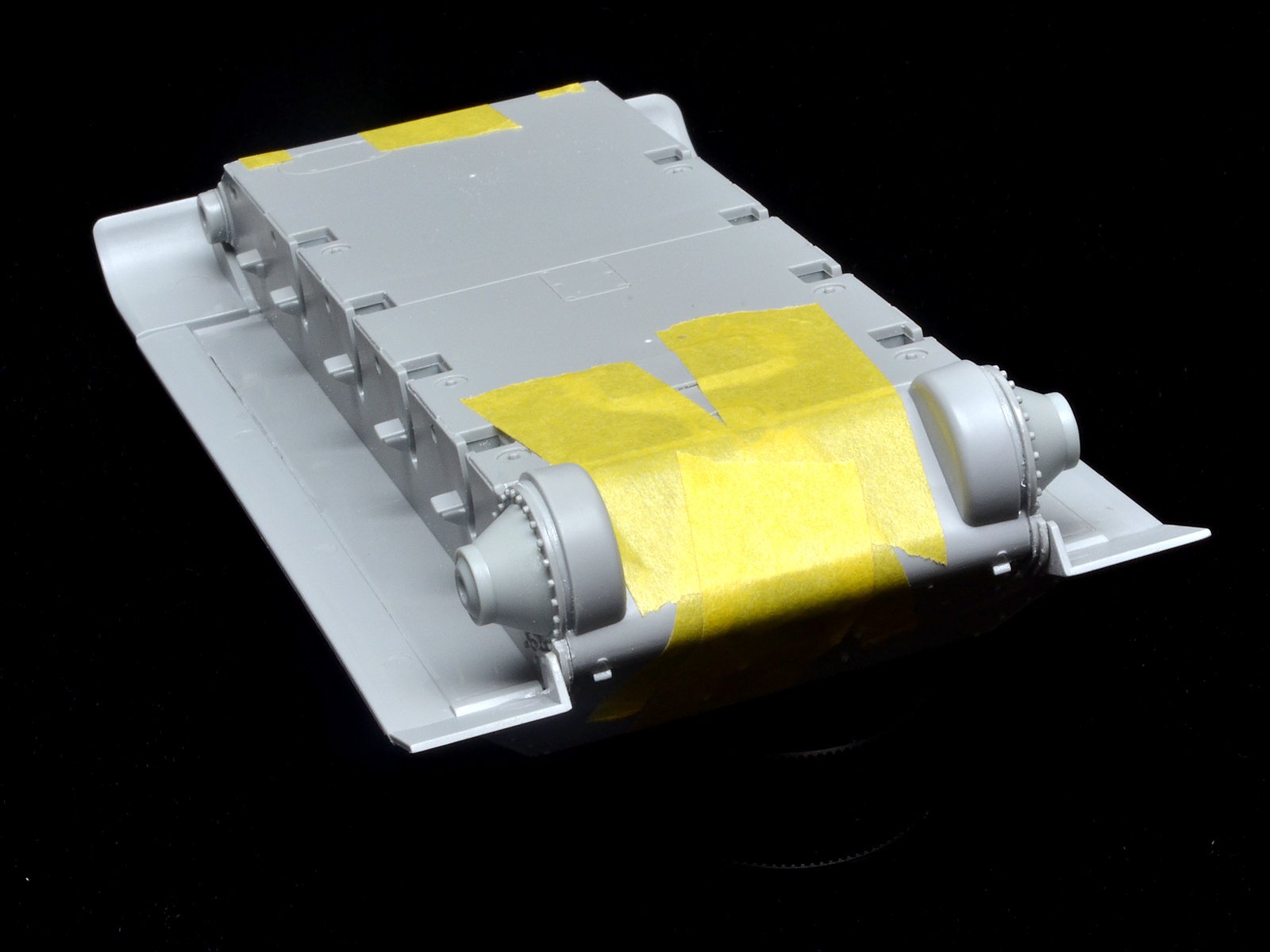
Step 3 assembles the road wheel arms (Q15, Q17, Q18) and drive housing (A5) while Step 4 deals with the hull underside, transmission cover, and installing the road, drive, and idler wheels. I found out the hard way that the best approach for installing the transmission cover is to wait. There are some serious alignment/size issues with this kit. After I spent about 45 frustrating minutes trying to figure this out, I went online to find out if others have this problem with the #6388 and sure enough there are lengthy threads on several forums about the poor fit of the hull. Basically the top hull is 1.5mm too long. This throws the rear plate (R29) and transmission cover (R5) out of alignment.
At this point I took a detour from the instructions and tried to address this issue first. If you get the rear plate and transmission cover to fit properly, there is a large gap under the fenders and the part lifts too high. This also results in a gap when the nose armor is installed (C3). If you start at the nose and work your way back, the transmission cover doesn’t fit. To try to get things to fit without a visible gap, I first filed and sanded the upper and lower hull in the nose area to get a better fit. I also trimmed the alignment pins and flatted the back of C3. For the rear, I kept trimming the underside edge of R5 until the transmission bulges sorta matched the drive hubs on the hull sides. It’s not perfect but shouldn’t be too visible.
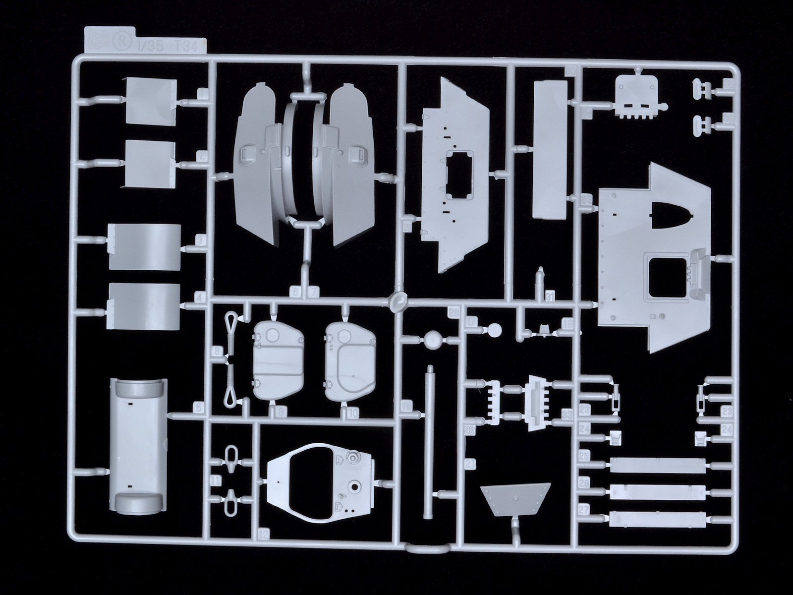
Step 5
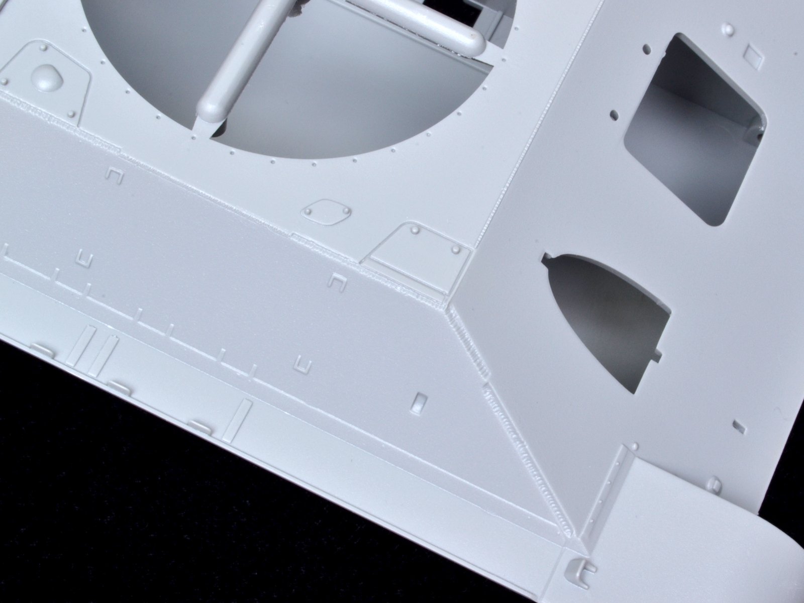
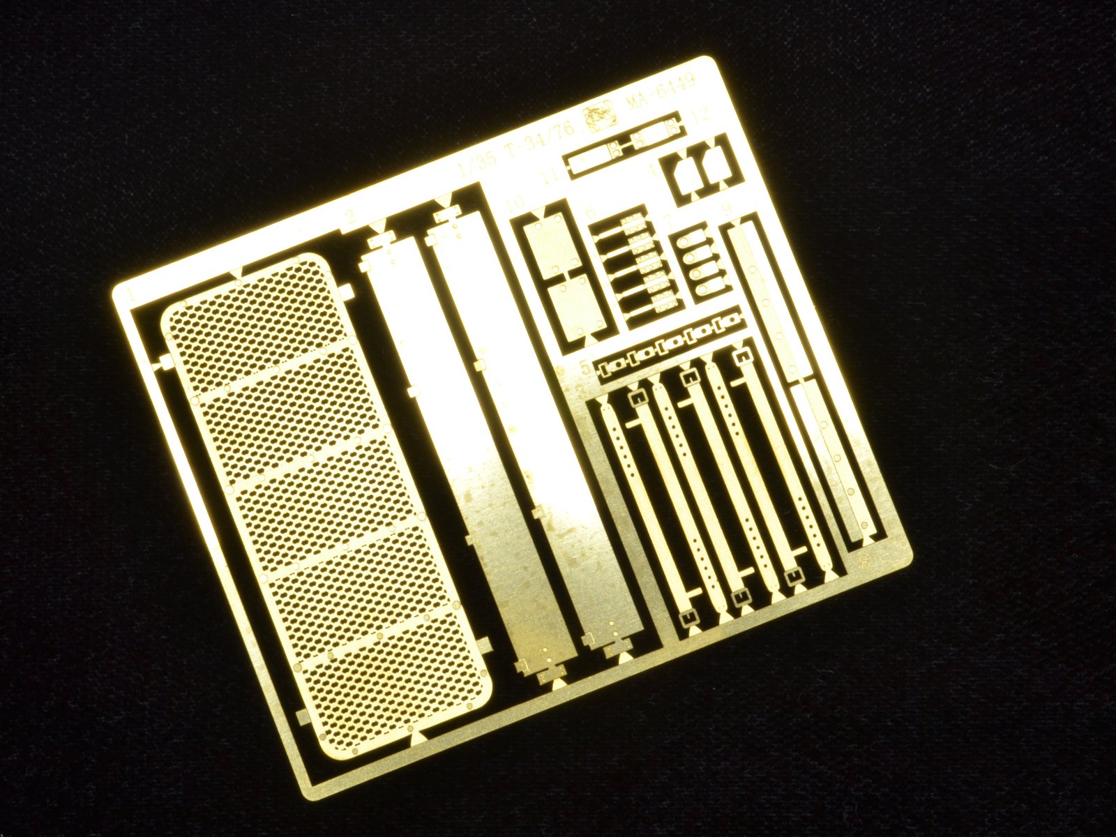
There is a lot going on in Step 5. There is even a small separate slip sheet with additional instructions to clip the sprue runner across the engine hatch. This is odd since no note is made of the sprue runners in the hull turret opening, and engine hatch opening. These obviously need to be trimmed too.
There is a call out for the upper rear louver hatch (G25) to use the PE screen MA1. The PE detail is nice but G25 has frame detailed molded in too. This needs to be carefully removed and then the PE can be installed.
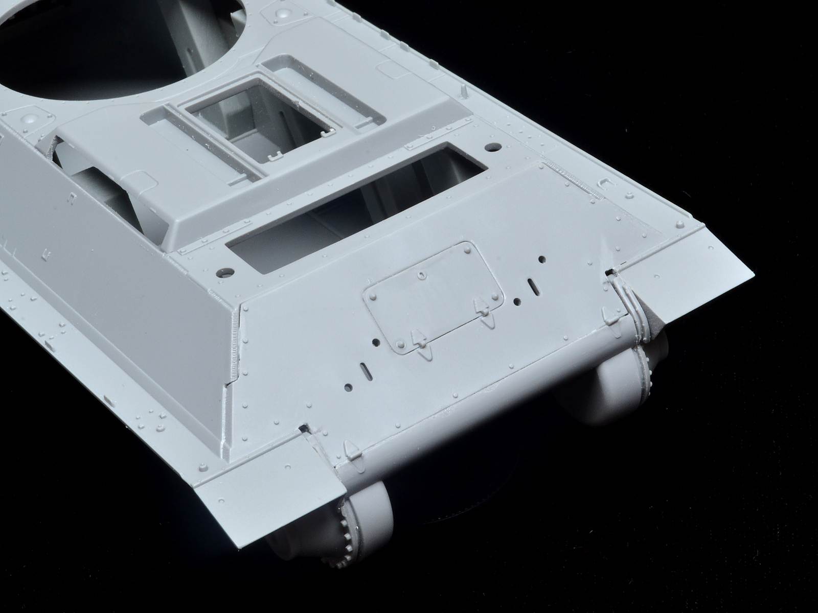
The kit fenders are molded integral to the upper hull. Some attempt has been made to make the side fenders appear more in scale, but the front and rear fenders are molded ridiculously thick. Even from molds a few years old they are thick. These should be thinned with a motor tool and good cutter or replaced with AM brass.
The kit includes both early and late intake vent grills. The correct intake vents to use are H3,H4,H6 & H7. These are molded solid which is fine since there is no engine detail to see. The kits parts are OK to use in my opinion because most AM sets simplify the details and they don’t accurately represent these either. The side vents are molded with a rounded top corner but the rectangular hole in the side of the hull has squared off corners. This mismatch can be fixed with filler.
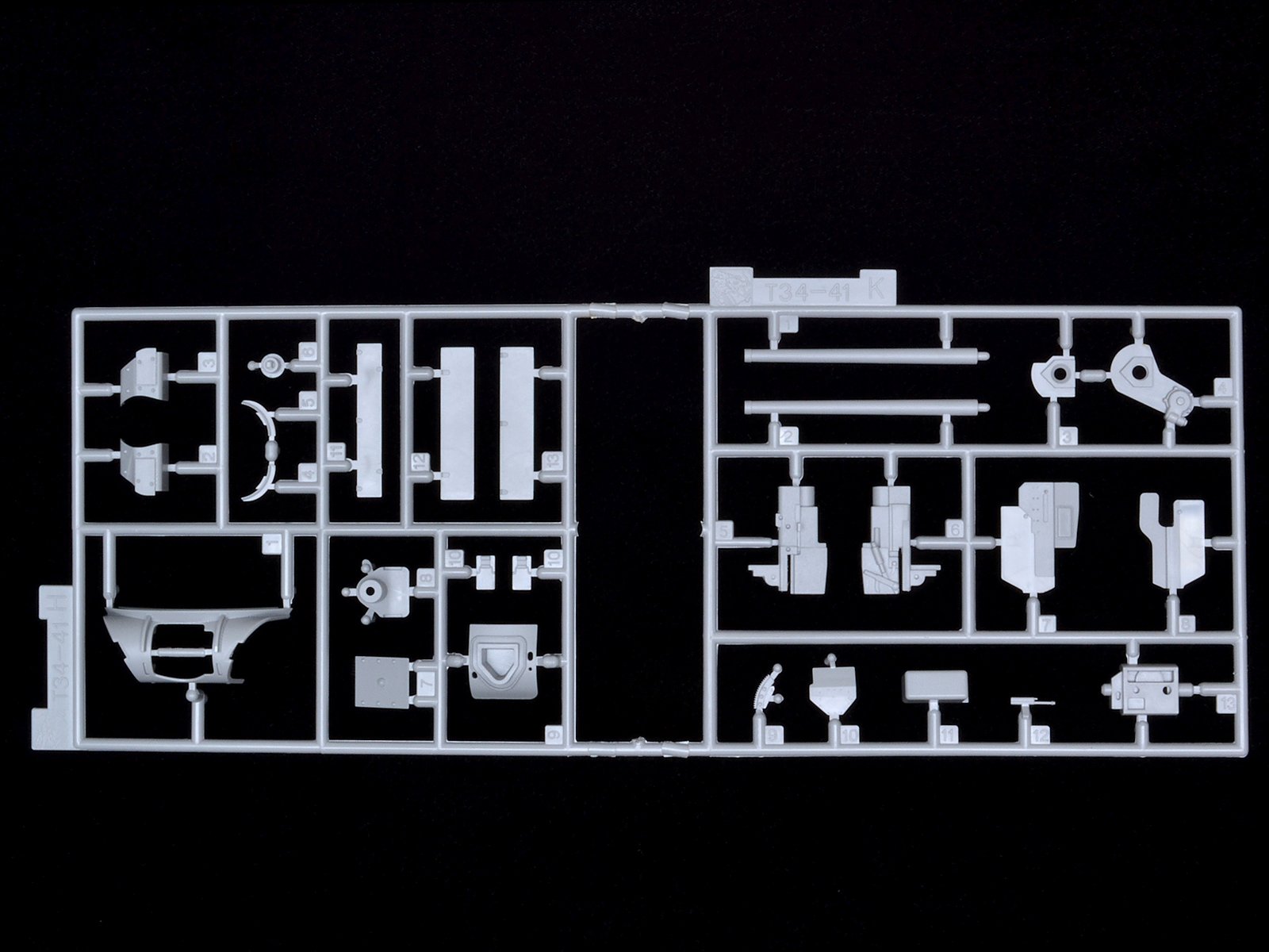
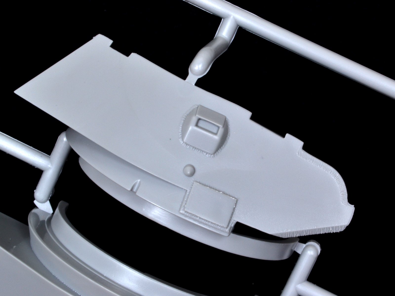
Step 6
Here you install the front MG parts and driver’s hatch assembly. The periscopes A12(A13) are molded separately but the rectangular holes in the hatch need to be opened up with a file for them to fit. If you want to show the armored periscope covers closed (R35&R36), skip the periscopes as they won’t otherwise close.
Steps 7 & 8
The fender items are installed in these steps. Dragon includes nice PE details to accent the side stowage boxes. In Step 7 there is a callout to install the straps to secure the ice cleats on the fenders. The PE straps are nice but the instructions show the straps passing through the fender tie down points which is a challenge since these are molded solid. To use the straps the solid tie downs will need to be replaced with fine wire.
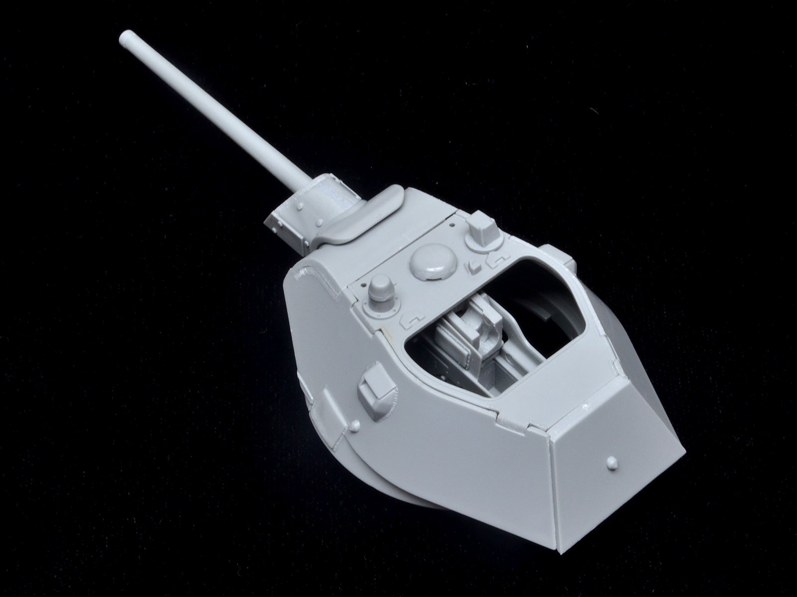
Steps 9 & 10
These two steps build the main gun and turret front. The placement of the shell catch basket K11 is vague. It gets installed between K8 and K7. K3 and K4 hold the main gun and allow it to elevate. The fit is very loose when installed and the main gun will be better off glued in place. The mantle S15 & S16 assembly and mantle plate S13 will need weld beads added to the joint.
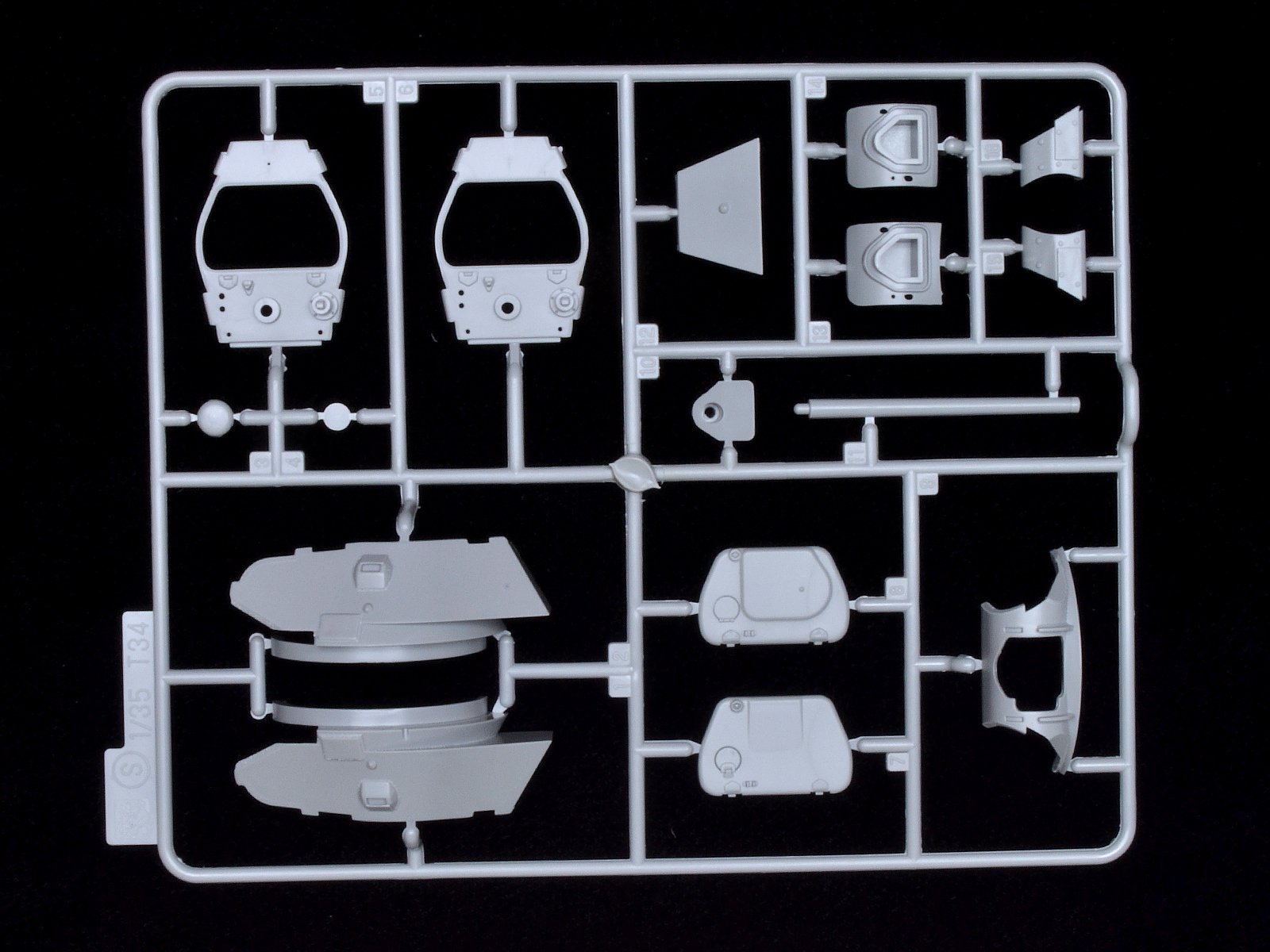
Steps 11 & 12
Here you assemble the turret. The turret halves have nice weld and flame cut edge details. Some welds will need to be cleaned up. There are numerous optional parts for the turret top and hatch. You will need to check references for a particular combination but I found a photo with R18, S3, and C12 as shown in the instructions.
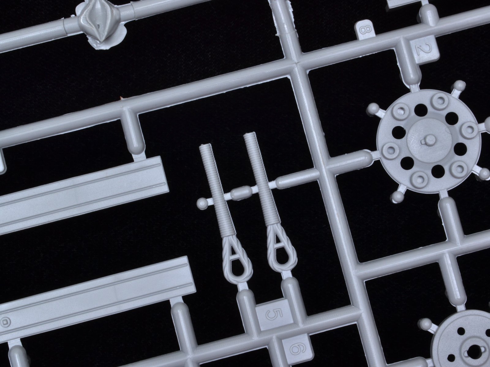
Step 13
This covers the final assembly including PzIII stowage bin, tow cables, and tracks.
Markings
There is only one decal and finish option shown in the instructions. They are for a vehicle repainted and used by the Pz. Rgt.31, 5.Pz.Div., Russia 1942. I found a photo online that closely resembles this vehicle and the markings seem to match.
Conclusion
The nice thing about this kit and Beutpanzers in general, is there is some flexibility in options, color and finish. Some units sent the captured vehicles back for a complete overhaul and repaint with additional armor and commander’s copula added. Others simply brought the tanks back to running condition and sent into service with little more than over sized Balkenkruze.
This is a nice way for a German armor fan to build something besides a panzer but the oversized upper hull and fit issues will turn some people off from this kit.
Thanks IPMS USA and Dragon Models USA for the opportunity to review this sample.


Comments
Add new comment
This site is protected by reCAPTCHA and the Google Privacy Policy and Terms of Service apply.
Similar Reviews