
Panzerfahre Fahrendeck mit Gepanzerter Landwasserschlepper (Prototype Nr. 11.)
(Editor's note: This kit is from Dragon's "Smart Kit" line)
History and Performance
During their early offensive operation during WWII the Germans were faced with several river crossings. Taking bridges intact was always a goal, and when that was not available bridging units were brought to the front. The Wehrmacht did not have any true means of amphibious crossings on hand during the war. The Landwasserschlepper was the initial solution to the river crossed challenge.
The Landwasserschlepper was a large amphibious vehicle that carried troops or cargo internally. Several experiments were made with a barge that connected two of these vehicles together. The concept was eventually discarded mid-war as something that was no longer affordable. The vehicle modeled here is the prototype of the armored version.
The Kit
The kit is molded in the grey plastic typical of the current Dragon line.
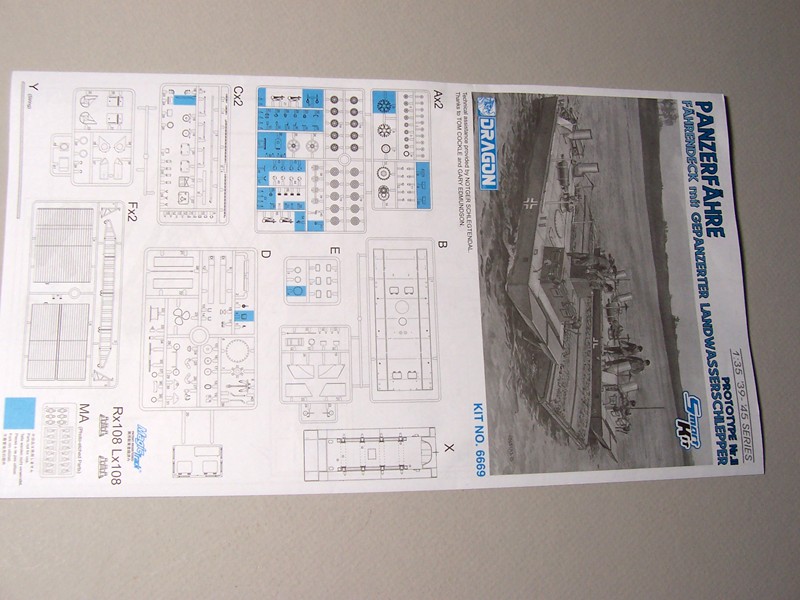
Instructions
The instructions follow the familiar Dragon format: six fold-out pages with exploded view subassemblies. There are 12 major steps to the construction, with several small subassemblies noted. The last step shows the completed vehicle alongside the barge, and notes that a second Landwasserschlepper kit 6625 is “sold separately”. Kit 6625 must represent the production vehicle.
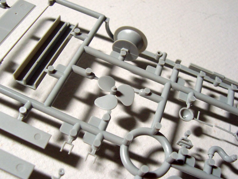
Sprues and Packaging
There are eight sprues molded in grey plastic. All sprues are packaged in clear plastic bags. The instructions note those parts that are not required in this build. There was no flash on the parts.
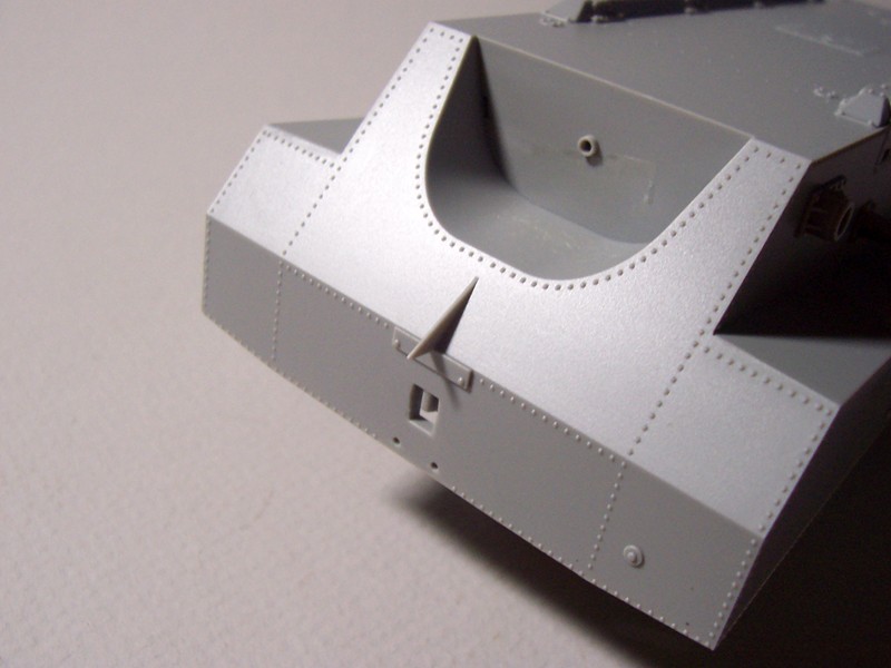
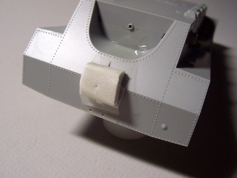
Hull and Upper Deck
These parts are molded and packaged separately. There is a small rubber pad tapped to the rear of the hull to protect the pointed end from damage during shipping. Both parts are detailed with loads of rivet heads. There are four hatches in the deck that may be posed open, but there is no detail within the cavernous hull.
Clear Parts
There is a small sprue for the rectangular window ports and spot lights. There is a larger circular part that has no home indicated in the instructions
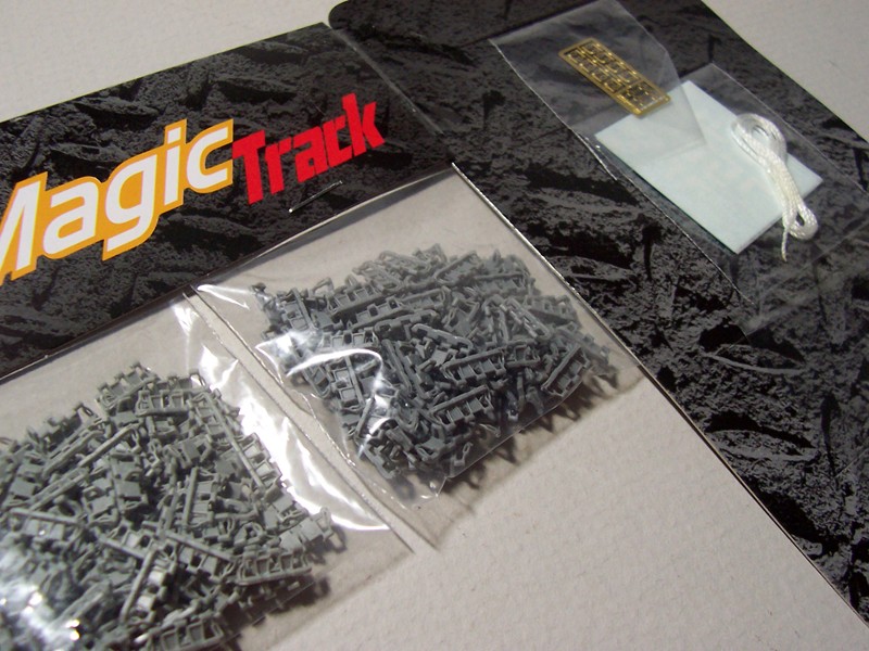
Photoetch
There is a small PE fret for the end loops for the rope railings. These parts are quite delicate and will challenge the eyesight and require a steady hand to form and install.
Figures
There are no figures included.
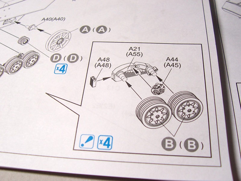
Running Gear and Tracks
The running gear and tracks are based on the Pz. Kpfw. IV vehicles. The instructions note that 105 link/side are required.
Decals/Markings
There is a single set of markings for this vehicle: with a number and crosses for the sides. There is one spare cross and numbers.
Miscellaneous
There is a strand of white nylon cord to be used for the safety railings.
Construction
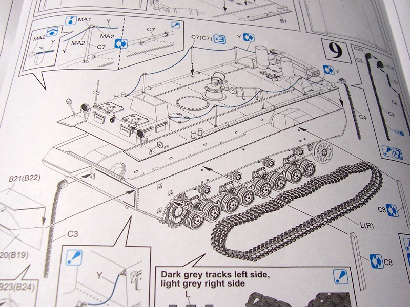
Running Gear and Tracks
This is the most tedious part of the project. There are 16 pairs of road wheels and eight pairs of return rollers to assemble and clean up. I found that parts A40 (rear idler axle) must be installed 180 degrees from what is shown in the instructions is order for the idler to fit. Care is also required to properly install the road wheel spring assemblies to assure proper alignment of the wheels. The shaft for the rear idlers was a bit too large in diameter for the idler to fit. Some scraping and sanding was required. The return roller mountings are a bit tenuous. The openings in the hull brackets are a bit too shallow and should be drilled out for a more solid fit. There are 105 individual track links per side. You should plan on several hours of effort to complete the running gear. Once completed, though, the assemblies really compliment the size of the vehicle. I did end up with about five spare links per side once the tracks were assembled and formed around the running gear.
Bridge Construction
Two small hatches are provided on the top of the bridge that can be posed open or closed. There is also a rectangular structure that appears to be the commander’s position. There is no detail for the interior, and therefore the interior should be painted black or fitted with crew to block view into the lower bridge.
The view ports are all equipped with armored, slotted covers that also can be posed open or closed. There are small; very small; very, very small mounting brackets for the covers. Each fit into a small depression on either side of the vision ports. I used a hobby knife blade and my finger tip to hold the parts while cutting each free from the sprue. Each bracket has a shallow dimple on one side. Using fine needle point tweezers I managed to mount most in place, and ping only one off the work bench into another time zone.
The two parts (C-6) mounted on the rear of the bridge were way too tiny to safely remove from the sprue without damage, and were replaced with copper wire super-glued in place.
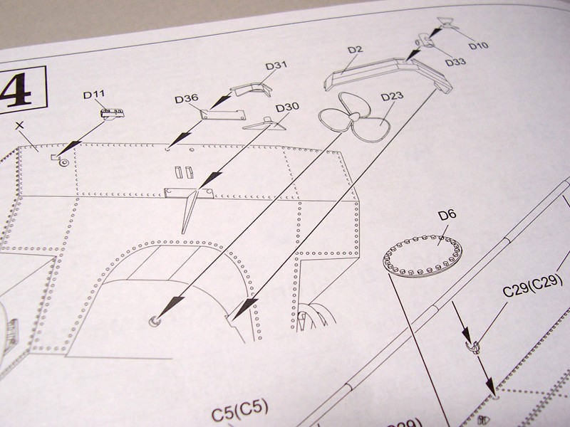
Hull Construction
The rear hull construction is shown on Detail 4. As noted previously the hull is packaged with a small protective rubber bumper on the triangular rib. Installation of part D30 reinforces the rib, but caution is still recommended to avoid damaging this detail. There was no mounting hole for the tail light, therefore some care and a steady hand is required to mount the light. I held off mounting the propeller so that it could be painted separately.
Upper Deck Construction
In Step 5, direction is given to open one small opening on both sides near the bow, but the instructions never show what is to be fitted into these opening. I believe that parts A1 fit into these openings and those parts are required for the later production vehicle.
Step 6-F shows the construction of a rectangular mechanism with a pulley wheel on one end. There are two mounting frames on either end. I glued the frames in place to assure the box would be centered correctly. Once the joints hardened I fit the box in place. It was a very tight fit, and care is required not to break the frames. Everything fit, but it was a bit concerning.
I then assembled the two exhaust mufflers to be installed later after painting and weathering. The exhaust pipes are molded with open ends.
Step 7-G shows the assembly of the two different centrifugal ventilators. The lower detail is appropriate for the vehicle.
How many tracked vehicles are equipped with an anchor? This one is, so I planned to install this later after painting and weathering. I would also plan to add a small length of chain at that time.
There are three stanchions on each side of the deck that are used to attach the safety ropes. I drilled out the mounting brackets for a solid join. Once installed these parts are vulnerable to damage, so care is required. The PE attachment rings were installed prior to fixing the stanchions to the deck.
This kit was full of interesting details: Step 9 shows the construction of two chains with hull mounting brackets. The chains appear as over-sized bicycle chains. The effort is fiddly and clean-up of the attachment points is best done once the chains are assembled.
Hull and Deck Interface
I actually fixed the deck to the hull before all of the smaller deck parts and sub-assemblies were installed. I felt there was a possibility that clamping would be required to close the seams between the deck and hull and I was correct.
In Step 9 parts C4 and C8 (bumpers?) are shown being fixed to the hull sides. If this is done, and the assembled track loops have not been installed, the tracks will not fit.
-
Safety Ropes and Attachments
- This part of the project was the most time-consuming and stressful. The tiny photoetch clamps (and there are 16 of them) consist of a small loop and a band that must be rolled and fitted around the cord furnished with the kit. Each clamp will fit over a small photo etch loop installed previously on the stanchions. Each clamp has a small slot on one leg that is intended to fit over the stanchion loops in order for the rope to span between the stanchions. The slot was so small I could not determine if it were actually open or was just impressed in the surface of the PE. I could see that this would be difficult (iof not impossible) to fit over the stanchion loops.
It took two tries before I acquired a rhythm and could fabricate each clamp without too much effort. After cutting the clamps from the fret I held the clamp firmly on a hard, flat surface with a metal rule lifted the clamp leg that was slotted for the stanchion loop attachment. This action opened the loop up slightly, but enough to fit over the stanchion loop. The band was rolled over a common pin shaft, but did result in a small section of band that stood out. This could be rolled tight later.
The length of nylon cord furnished with the kit had a tendency to fray when cut, and was therefore replaced. My wife came to the rescue with a cotton covered polyester cord as manufactured by Coats. This thread was slightly smaller than what came with the kit, but had the distinct advantage of not unraveling when cut, plus is appeared more in scale than the kit-furnished material. Being cotton covered also had the advantage that the thread could be colored with a permanent marker, ink or paint.
Barge or Ferry Construction
The barge construction consists of just fourteen parts. Care is required to completely eliminate the stubs from the sprue attachment points for the hull bottom, the top deck and the side. The top decks have concealed male fittings that fit tightly into female fittings on the bottom. Snug this connection tight to assure the proper fit of the top and bottom. There is a centerline gutter on the deck, and a small gap occurred when the two halves were fitted together. No amount of pressure effort eliminated the gap. This was filled with putty and sanded smooth. The finished barge is 11” long by 4 ¼” wide.
There are four swing arms on the sides of the barge. These may be installed loose and will pivot 180 degrees and are meant to be attached to the chains noted above. Being loosely fitted they did have a tendency to pop off occasionally.
Finishing/Painting
There is only a single painting option shown in the instructions: Panzer Grey lower hull and barge bottom and sides, with light grey upper deck structures and surfaces. The instructions show a scuffed light grey paint and exposed wood on the barge deck. Tamiya paints were used throughout. Wood grain was simulated with oil paints.
Decals
I applied a few coats of clear acryl gloss to the surface. The decal clear portions appeared "cloudy" on the backer sheet, but once immersed in water and lifted from the backer regained a transparent appearance. The decals were applied with MicroSet and MicroSol and reacted well to these liquids. The clear portions became truly clear once applied to the models surface.
Conclusion
This is a unique vehicle and is recommended for those who are looking for something a bit different. This is an interesting topic: a tracked armored vehicle with a boat hull, propeller and an anchor. With the purchase of a second tracked vehicle a diorama possibly is there. Loading the barge with a light tank or similar vehicle, along with miscellaneous supplies offers many possibilities. If you go in this direction, first make sure that there is room on the display shelf: this will be a rather large display!
In my opinion, some of the very small parts, while adding to the overall parts count, are more of a nuisance than a feature. Some are too small to remove from the sprue without damage, or are just too small to handle without the risk of loss. If used, a steady hand and keen eyesight are an absolute must. The quality of parts is current with the familiar high Dragon standards.
The connector chains fitted between the vehicle and barge are not meant to be a permanent connection, unless the models are set permanently in a diorama. If this is the goal, I would recommend that after the chains are assembled they be softened with liquid solvent, then after ten minutes or so be formed between the vehicle and barge. Paint the chains after the plastic had hardened.
The instructions are confusing in some of the steps. It would appear the same instructions will be used for the prototype and production vehicles. Some of the steps show openings for the production vehicle being opened or drilled out: Look ahead to some of the next steps and determine if the work is required or not. I did end up filling some openings that were unnecessary.
Overall, there were no major fit problems, but dry-fitting of parts and subassemblies is always a recommended procedure. This was a rather quick build and is not overly complicated. I truly enjoyed the effort and would recommend this kit for those interested in something really different. The cost is not unreasonable for the interesting subject and quality offered.
I thank IPMS/USA and Dragon USA for the opportunity to build and review this kit.

Sample instruction page

Sample instruction page

Parts tree example
Parts tree example

Underside of hull

Clear Parts

Photoetch fret compared to US one-cent coin
Bags o' tracks, L & R
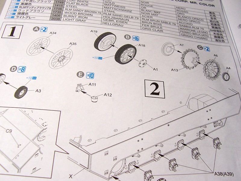
Running gear instruction sequence
Running gear instruction sequence
Rear hull instruction sequence
Rear hull instruction sequence
Rear hull instruction sequence
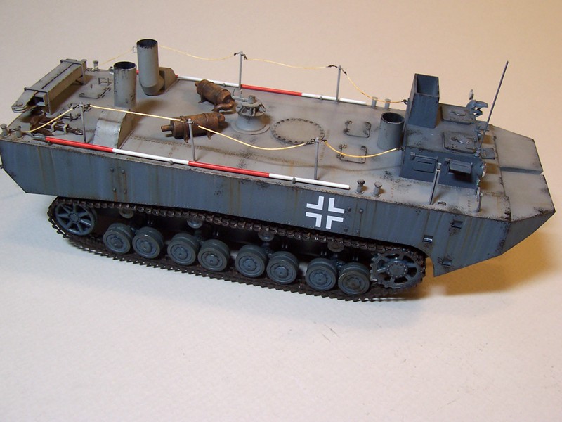
Completed Landwasserschlepper

Completed barge
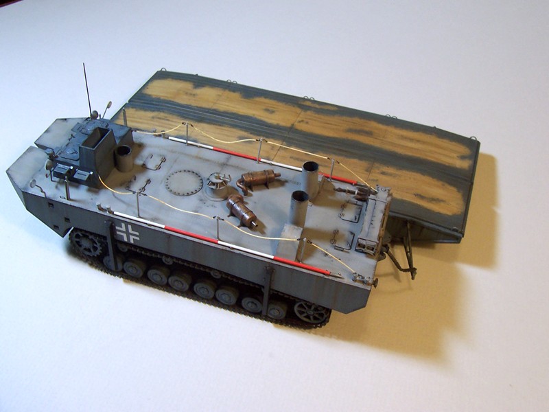
Completed Landwasserschlepper alongside barge
Deck construction sequence

Comments
Add new comment
This site is protected by reCAPTCHA and the Google Privacy Policy and Terms of Service apply.
Similar Reviews