
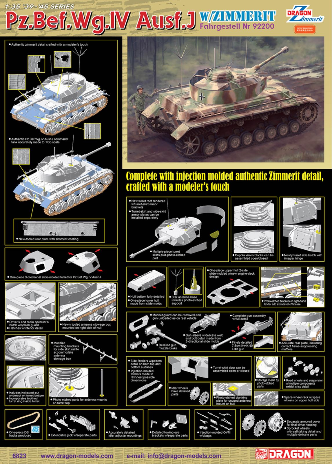
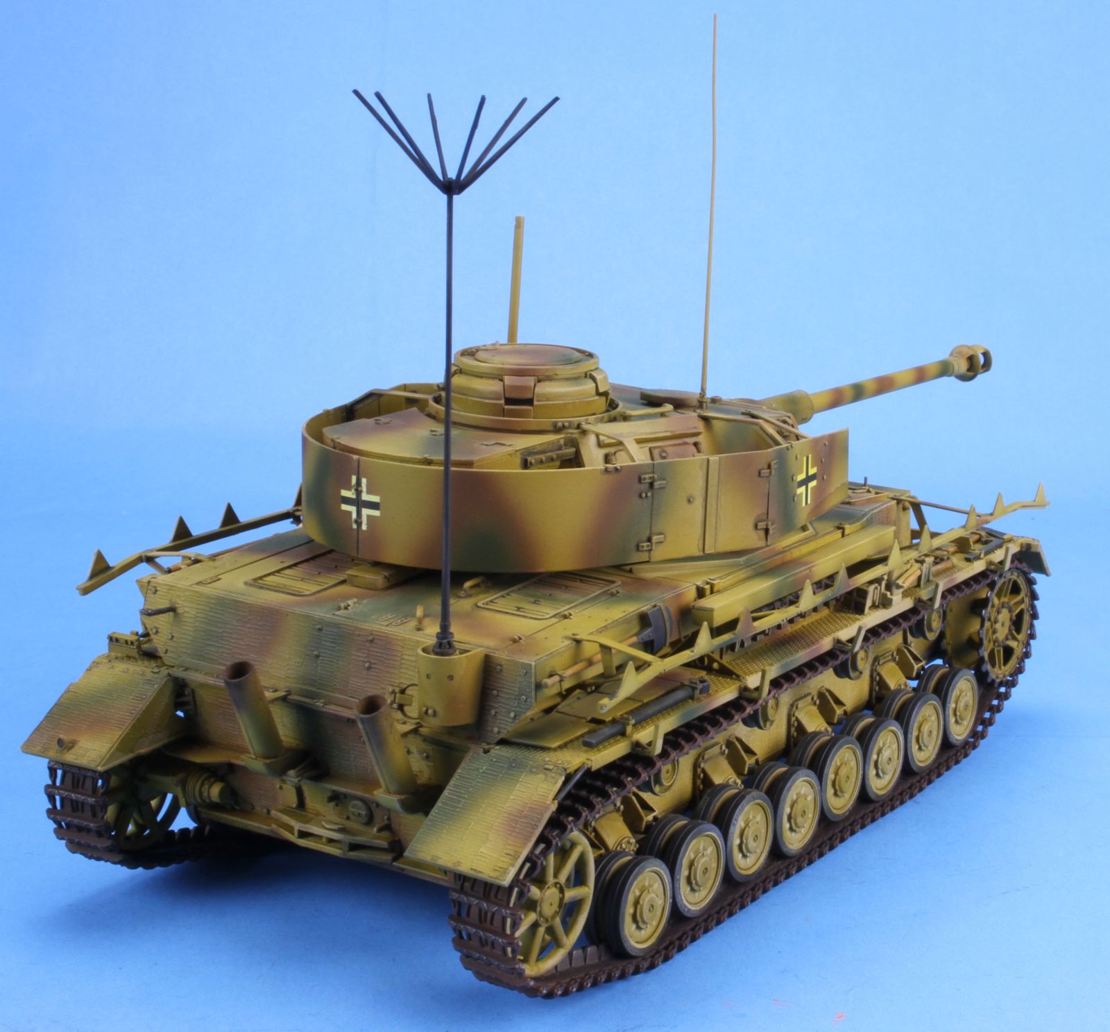
Panzerbeobachtungswagen IV Ausf J w/Zimmerit Fahrgestell; Nr 92200
This is a multimedia kit comprised of 470+ styrene parts on 24 sprues, DS tracks, one photo etched fret, decals and the set of instructions that need to be reviewed very carefully before gluing any parts together. The DS tracks were packed well enough to not be misshaped with the guide horns flattened as it has been noted in the past.
Most Dragon models today are a collection of old sprues and new sprues added to create a new kit variant. In this case, Dragon has done so and you will have some sprues with the same letter but are called out by the color and sprue letters in upper and lower case.
There are not many options for you to choose between and none require you to do so before you start. You can pick as you go along.
Step 1. This step is the assembly of the idler wheel, drive sprockets, and return wheels. You will need to choose the style of idler adjustment mounting you want to use. One style of idler wheel has a Photo Etch wear ring on the inside, but instead of one piece, you get 3. I did not use them, but it appears that the assembly would be more difficult than the one ring. Either style is moveable, so you should not glue them in place as to be able to adjust the track tension later in step 21.
Step 2. This builds the rear plate.
Steps 3 & 4. In these steps the chassis is built. There are 6 mold stubs on the top of the chassis tub that need to be removed. If you don’t remove these stubs the fenders will not fit. This is not noted in the instructions. There are three optional front plates in the kit. The instructions call out part (blue) B4. This part has no zimmerit. Alternates are S9 or T1, one is partially covered with zimmerit and the other is completely covered with zimmerit. I could not find some photos of this tank (I assume the kit was designed to follow a specific tank because of the serial number). I chose T1 with full zimmerit.
Step 5. This step is the detailing of the rear plate.
Step 6. This step adds the running gear to the hull chassis. When you attach the wheel springs (A21 & A55) if you use glue sparingly on the cap (A42 &A43) this will allow a little wiggle room to make sure the road wheels are flat and level. The road wheels have a large seam in the middle of the tire. I assume that they are to be that way and not a mold seam to be removed. I made that choice as the rest of the sprue had only faint mold seams. I left the road wheels off at this time for ease of painting. On front top plate part blue T3, the instructions show 5 holes to be drilled in it for the mounting of the spare tracks. Don’t do it. There are no spare tracks in the kit to be added. This is left over from prior kit instructions. You can add tracks from your spares box if desired.
Step 7. This step adds the fenders
Step 8. This step builds the hull machine gun and mounts it in the front vertical hull plate. The instructions are mismarked on the machine gun handle. The part called out should be H65, not H66.
Step 9. This step builds the upper chassis side plates. You have the option of drilling out holes for the mounting brackets of the side shields, or leaving them blank and leaving the side shields mounting brackets off. Even though the kit has the side shield mounting rails, there are no side shields include. If you want to add these, you will need some from the spares box or an aftermarket photo etch. The instructions show photo etch plate MA17 being added to the rear plate blue T2 after you have drilled a hole in the plate. However, the rod A52 will not fit thru the PE plate MA17. You may want to drill out the hole on plate MA17, or just leave the plate off and glue the rod M52 directly to the hull plate.
Step 10. This step adds the upper hull to the lower hull. There were no specific problems here.
Step 11. This step adds the on board tools to the right fender. You do have a choice of starter handles E4 and E5.
Step 12. This step adds the on board tools to the left fender.
Step 13. This step builds the commanders cupola. You can choose to show the vision slot armor either open or closed. The instructions are mismarked. The closed part is M4 and the open part is M5.
Step 14. This step builds the gun and its mounting brackets. You can choose to use the machine gun part G23 or just the empty machine gun armor part G26.
Step 15. This step completes the gun with the breech and recoil guards. You have two options for the breech block B46 or B9. This is a choice without any real effect as once the gun is mounted even with the hatches open, you can’t see this item.
Steps 16, 17& 18. These steps build the turret both inside, outside and mounts the gun. You can choose between plastic and photo etch aiming vision pointer M8 & MA7. You also get a choice of side shield doors either one piece L10 & L12 or two piece doors L3/L9 and L7/L8. The photo etch screens will fit down into place if the supports C1, C2 and C3 are correctly placed and the arm is vertical and not pinched in toward the turret or the side shield.
Step 19. This step either mounts the side shield mounts and rails or just the empty mounting plates (P12 – P15.
Step 20. This step adds the spare tracks using two photo etch plates. I super glued the plates to the tracks first, then after that was set, I glued them to the hull.
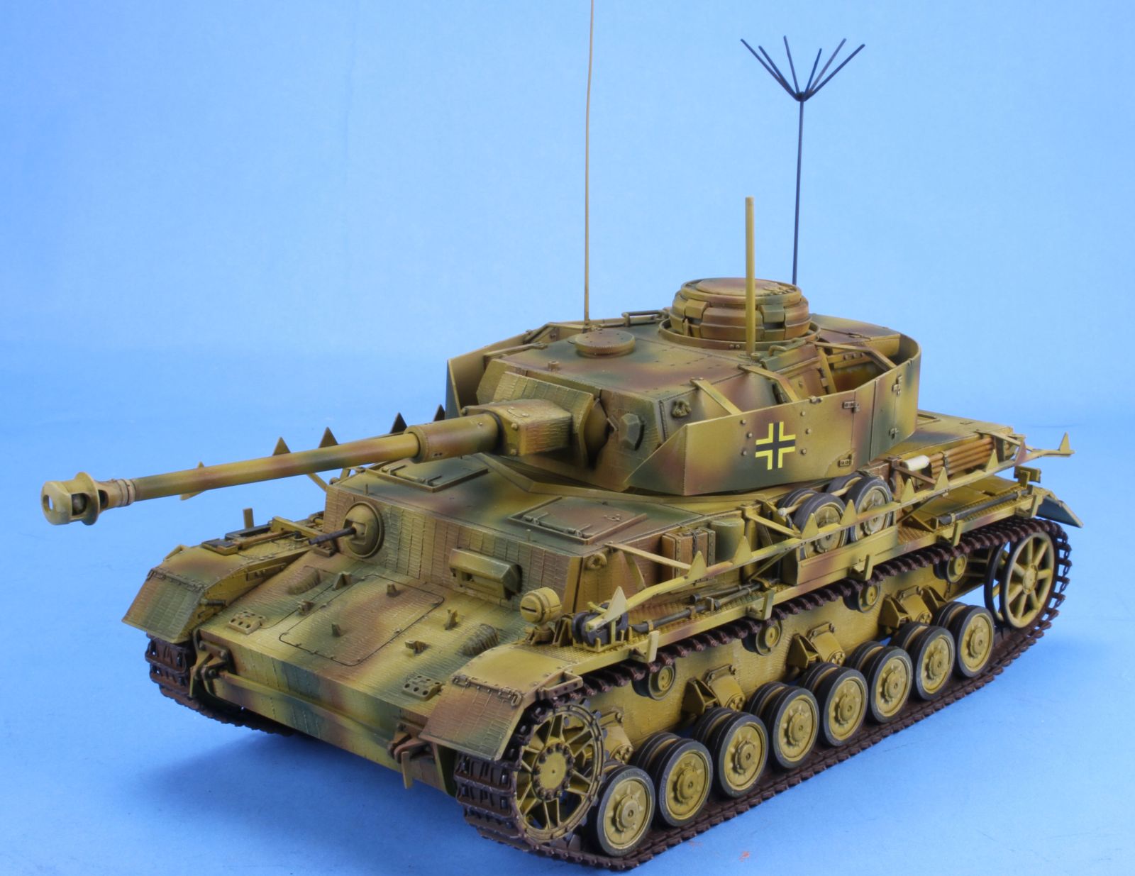
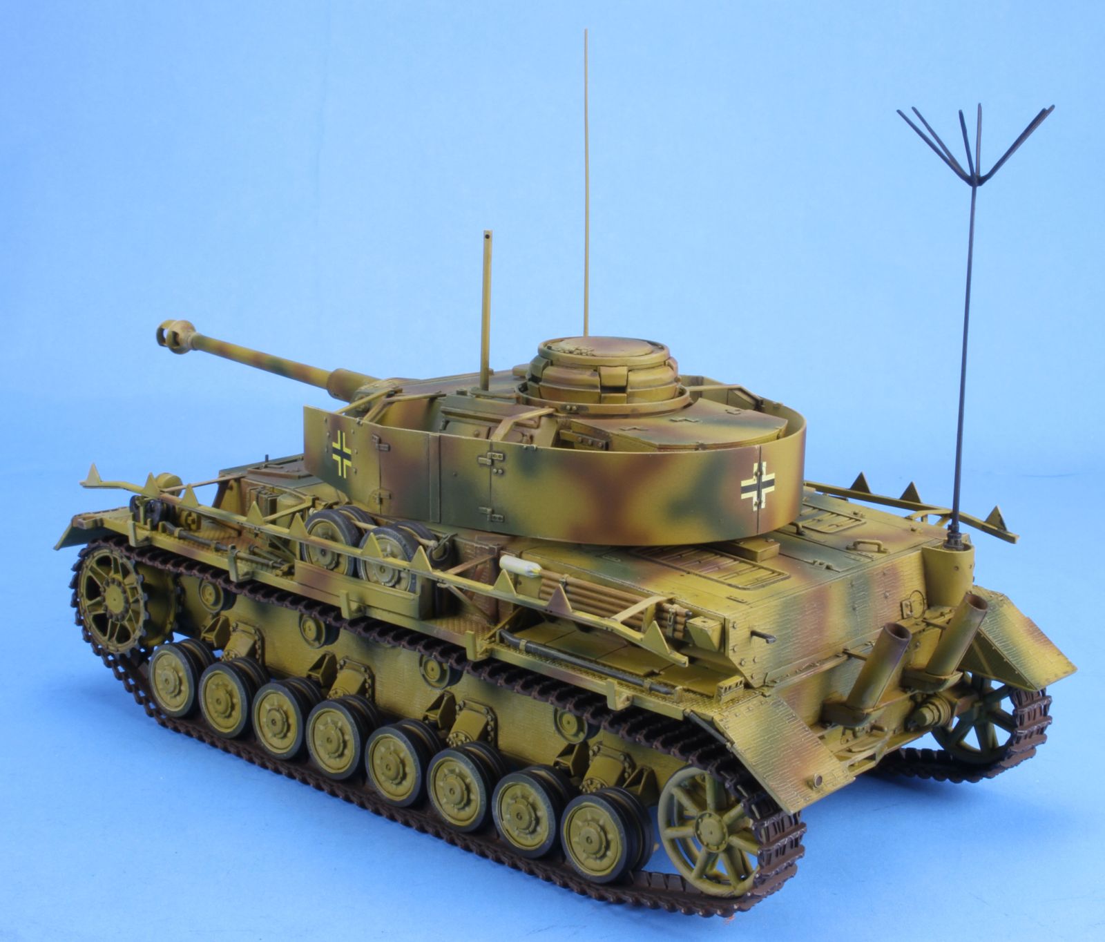
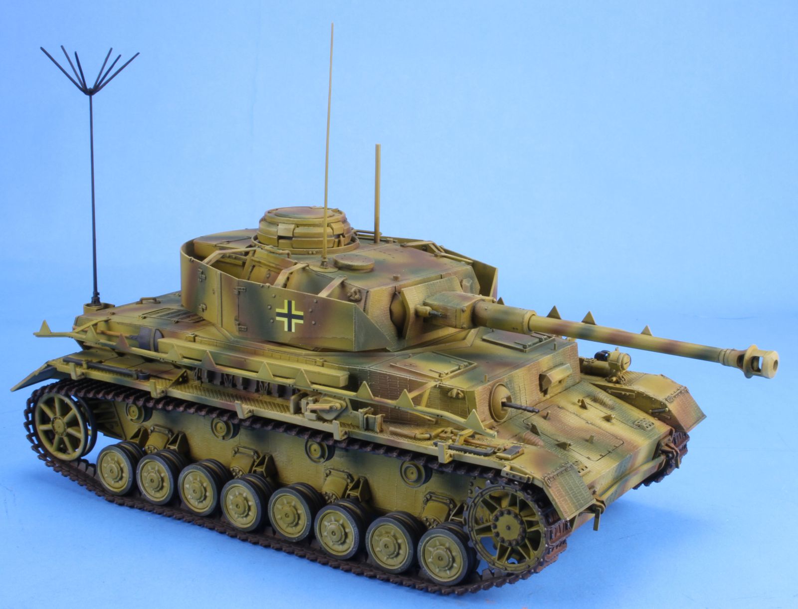
Step 21. This step adds the tracks and the star antenna. I suggest that you leave the antenna off until you are finished painting and weathering the model. I can speak from experience that you will break the antenna during the painting. I used HobbyTrax forms to get the tracks into the proper shape with a little sag depicted.
Accuracy
The drawings found in the references listed below show the kit to be basically accurate. Since I’m not a rivet counter I don’t go beyond that. I model for fun.
Molding
I found the molding to be clean, with no sink marks and few ejector pin marks. The mold seams were easily removed and I saw no flash. Dragon makes extensive use of the pin nodes to keep ejector pin marks on the parts to a minimum. However, you will need to handle the removal and clean up of the parts with care.
Instructions
As with all Dragon’s instructions, read them carefully and plan what you want to do ahead of construction. Check the fit over and over and over again to make sure that all items fit together and are properly call out.
Painting and Decals
The color call outs are for Testors Model Master enamel and Gunze paints. The decals are by Cartograf and are up to their usual high standards, but there are only the balkencruz for the turret. There is only one paint scheme of an unidentified unit 1944.
Conclusion
This is a well engineered and molded model. If you make sure that the instructions are correct, the model goes together very well. It is a good mix of styrene and Photo-etch. I can recommend this kit to all WWII modelers.
References for this variant are included in the following books:
- Panzer IV & Its Variants Vol 1; Schiffer Publishing LTD, by W. Spielberger.. ISBN 0-88740-515-0
- Panzerkampfwagen IV; Panzer Tracts 4, by T. Jentz & H. Doyle. Darlington Productions, ISBN 0-9648793-4-4
- Panzerkampfwagen IV; Achtung Panzer 3.
- Panzerkampfwagen IV and Its Variants Vol 2. Schiffer Publishing LTD, by W. Spielberger, H Doyle & T Jentz. ISBN 978-0-7643-3756-7
Of course, there are others available.
Thanks to Dragon for the review sample and IPMS/USA for the review space.
This model can be found at most hobby shops, online hobby shops and at https://www.cyber-hobby.com/collections/dragon.


Comments
Add new comment
This site is protected by reCAPTCHA and the Google Privacy Policy and Terms of Service apply.
Similar Reviews