
OS2U Kingfisher Build
Thank you to the great folks at Kitty Hawk Models for bringing a welcome new large-scale kit to U. S. Navy propeller aficionados. Kitty Hawk subjects are starting to fill out my collection more and more! Thank you also to the IPMS Reviewer Corps staff members who do the hard work in getting us kits to review.
This new release from Kitty Hawk fills a long-standing gap in 1:32 scale early USN aircraft. The Kingfisher is represented in the scale modeling world by very old but generally still available smaller scale 1:48 and 1:72 kits, which can be upgraded and corrected by a wide variety of after-market components. However, I am unaware of any injection-molded Kingfisher kits in 1:32 scale, let alone a modern release. Thank you Kitty Hawk!
This build review follows on an earlier prebuild in-the-box review. Please refer to the earlier review for descriptions of the instruction layouts, decals, etc. I will summarize the construction, how the kit option choices turned out, and will shamelessly share my mistakes and fixes. A detailed step-by-step build log follows the review.
Overall Summary
The kit will produce a very nice representation of the OS2U in an impressive size. I am happy with the final product. I was very pleased with the kit in my initial review, in box. However, actual construction was challenging, sometimes frustrating, and occasionally baffling. While I was following the instructions, I found incorrect or absent part references, incorrect decal placement and interesting construction logic. The exterior surface detail is excellent. Smaller, longer, or thinner details and parts easily broke, even with careful cutting. During the prebuild review I did not note any unusual flash, however after I applied a base primer coat a subtle but pervasive edge of flash was common. I had to tweak and adjust nearly every part for proper fit. The distribution of complexity is unusual, for example the engine has a disproportionately large number of small parts, yet other areas seem not so complex. The instructions had some typos, and in one case referred to a part that was not included. The decal placement guide showed incorrect markings for the VO-1 example I chose to build, but I was able to substitute other decals from other versions on the decal sheet.
I really did enjoy building the kit and am pleased with the result, but I am now not convinced the kit is for a novice. It took time and patience to work through the issues described above; you should be an experienced builder to get the best out of the kit. Eduard will be releasing aftermarket detail sets and a masking set which will enhance the plane further. I also noted a Edo type of float and I am sure more aftermarket will follow. I recommend the kit, but with the caveat that completion may require more work than anticipated and builders should have more than few kits under their belts to work past the instruction errors and small bits included.
Construction
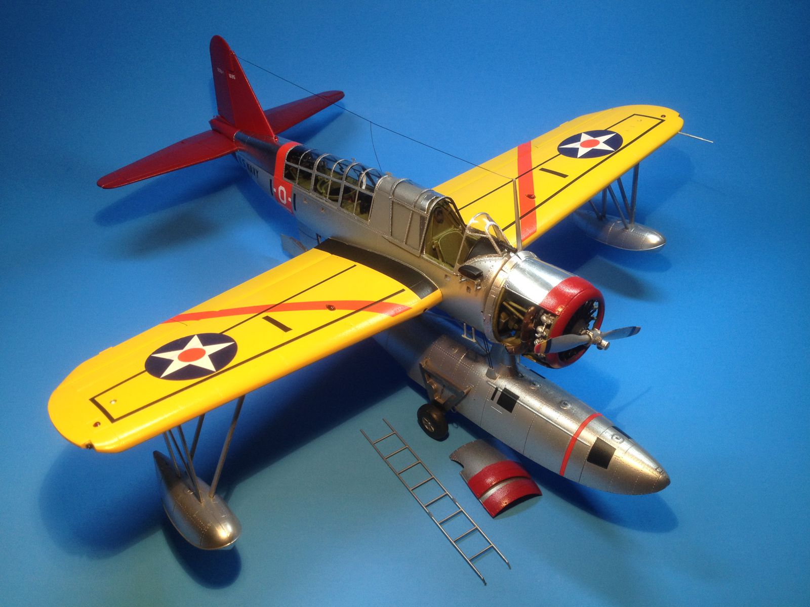
Construction was challenging, with problematic fit throughout. The build log below details the challenges on a step-by-step basis. I did elect to build the float version. Replacing the pylon bracing with plastic rod and installing 20 gauge wire to simulate float bracing was not difficult. Installing short brass tubes to strengthen the float-to-fuselage join was also not difficult, producing a very strong joint. The wing tip floats had some braces that were short, and I lengthened them by using braces from the unused parts for the wheeled version.
Decals
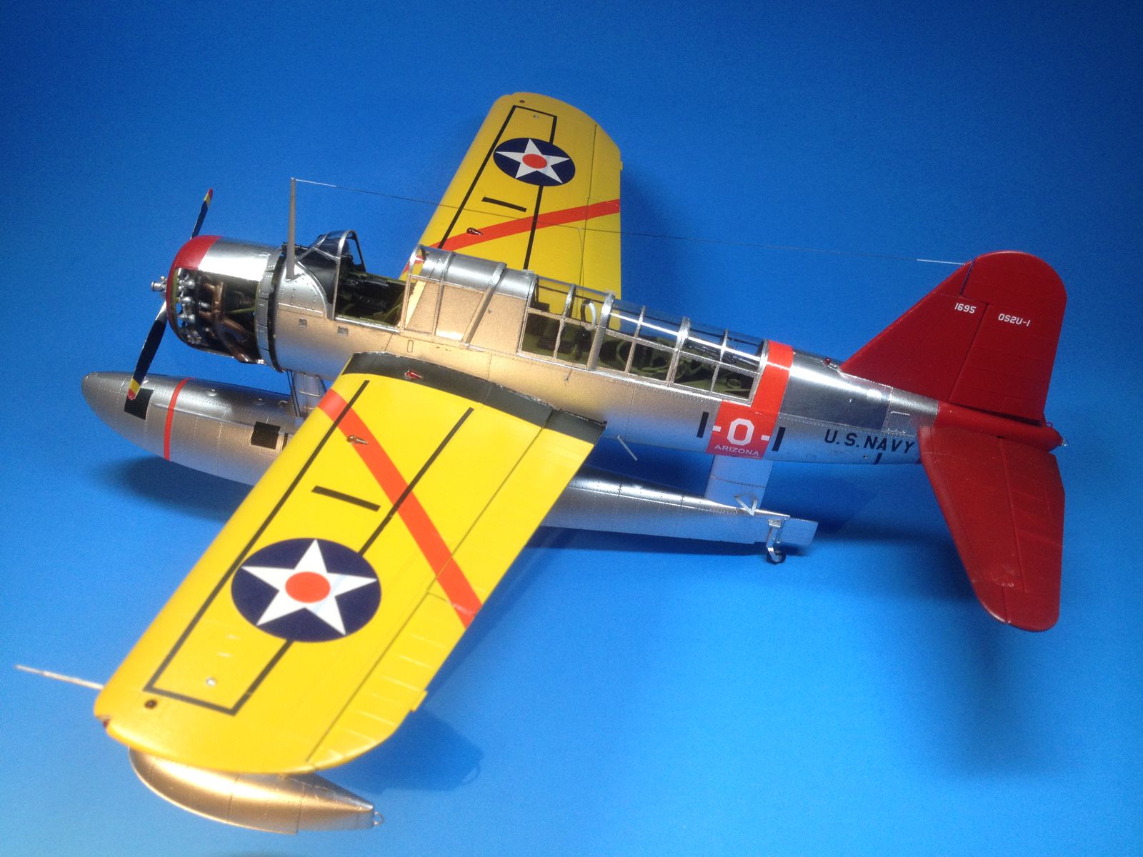
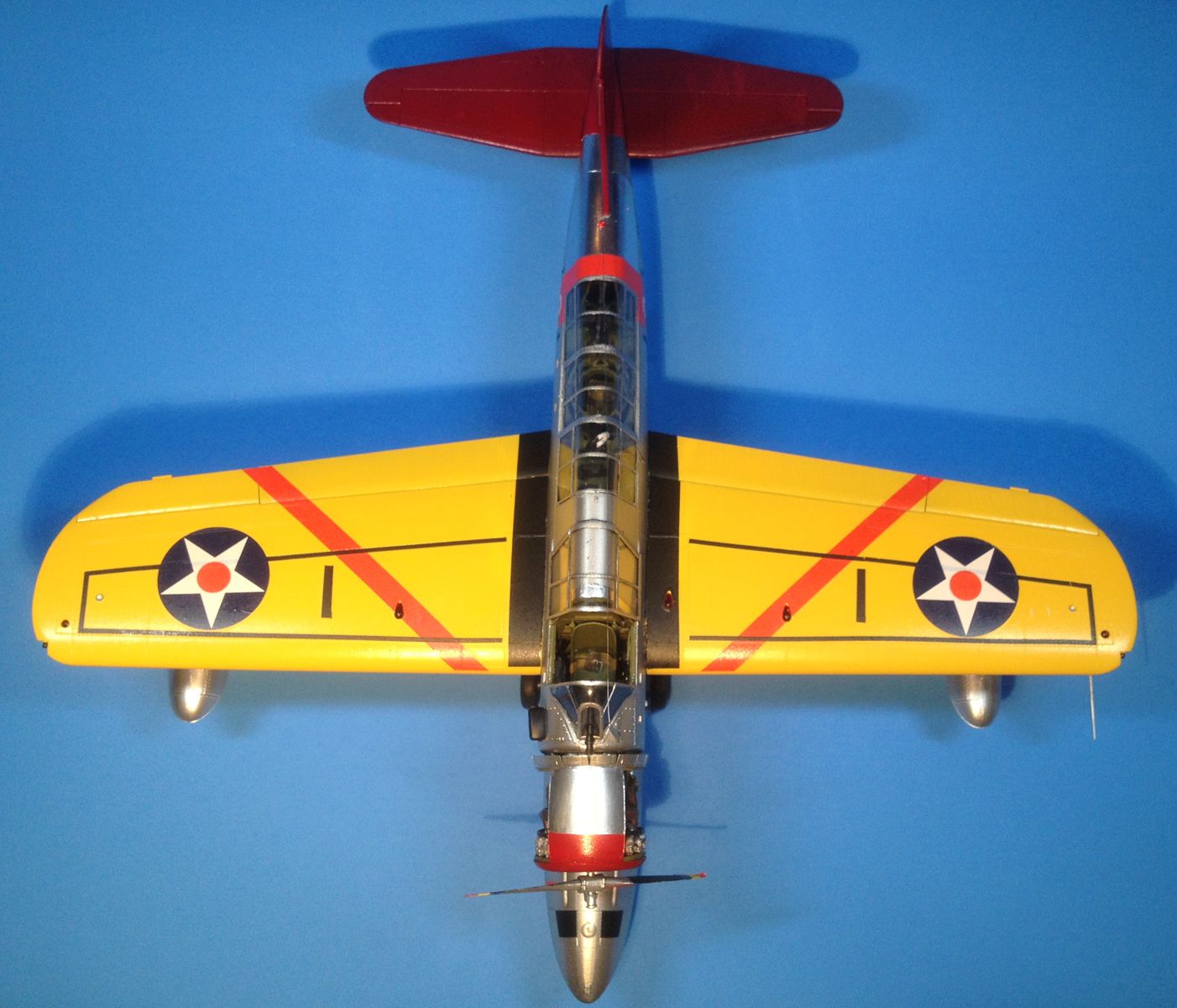
The decals worked very well with Microscale solutions and were very durable while being nudged into place. I really appreciated this characteristic on the long and narrow wing walkway stripes. Registration and opacity was good on all decals. The national insignia with red center was a little translucent over the walkway stripes. This see-through problem could be fixed by applying one of the unused versions’ white stars first, followed by the red-center national insignia. The decal placement sheet did not indicate red-center national insignia, but the red-center style was standard in 1941 on yellow-wing aircraft so I used them. The decal placement guide also incorrectly shows a “7” on the each wing top. The wing numbers should each be a “1” to match the numbers on the red fuselage band. I easily trimmed the provided “7” decal into a “1”. I painted the propeller in aluminum with a flat black rear panel, and used the red-yellow-blue tip decals, which were oddly unreferenced on the decal placement sheet for any of the versions.
Finishing
I used a mix of Vallejo Model Air and Metal Color acrylics, Testors Model Master Acryl, and Tamiya acrylics. I added a few panels of Bare-Metal foil to break up the aluminum monotone. I am very pleased with the Vallejo Metal Colors, and will like do more natural metal finishes using this product. The fuselage band and wing chevron color does not match the insignia red paint specs in the instructions. I suggest painting the chevrons and the fuselage band with the same paint used for the tail surfaces and the nose. The completed model looks great to me, but I am a bit biased on the yellow wings USN schemes!
Aftermarket
Eduard is releasing exterior and interior detail sets, and I hope they will also release a masking set for the expansive greenhouse canopy. Other vendors may release resin wheels, beaching gear, and so on. I am still hoping for a P-6 catapult!
Conclusion
This kit is an excellent value for the experienced builder and all of the preceding comments are not meant to be criticisms, but are a narrative of construction adventures. The choice of versions is superb, and Kitty Hawk’s overall treatment of a long-neglected subject is very welcome.
I recommend this kit! Thank you Kitty Hawk and the IPMS Reviewer Corps!
Build Log
General comments during construction in the hangar
- As many parts as possible were painted on the sprue trees. The various boxes and radios were all painted flat black and touched up after assembly.
- Color call outs are minimal and research was done for interior parts.
- I trimmed off many of the locating tabs and pins, because they were often oversized and interfered with assembly.
- The large part fit is very good, the smaller details not so good.
- The fit is consistently problematic. I found very few places where the parts showed a good join without trimming or sanding.
- Poor fit was not always a function of flash. Tabs and pins were frequently larger than the receiving sockets.
- Control surfaces were mounted in a slightly drooped or offset position as designed. This is a nice feature.
- I am certain that this model could be built in a contest winner. I would anticipate that aftermarket resin and masks will greatly add to the finished model.
- While overcoming the fit challenges is part of any model build, when I found myself being thrilled to find parts that fit well.
- The canopies fit very well.
- A front view anywhere in the instructions would be very helpful for positioning and aligning.
Step 1
- Engine construction, fairly straightforward
- Plastic seems a little soft.
- Trim slender parts carefully, I have many break while trimming from the sprues with Xuron nippers.
- Some slight flash on engine parts to be removed for good fit.
- Examine the directions very carefully for part orientation
- Assemblies drawing are sometimes rotated from one view to the next, and the rotation is not always obvious.
- This kit seems to be another example of CAD-generated instructions, written without the kit in hand and being built.
- Every locating tab on a part needed to be scraped, sanded, filed or trimmed to fit properly
Step 2
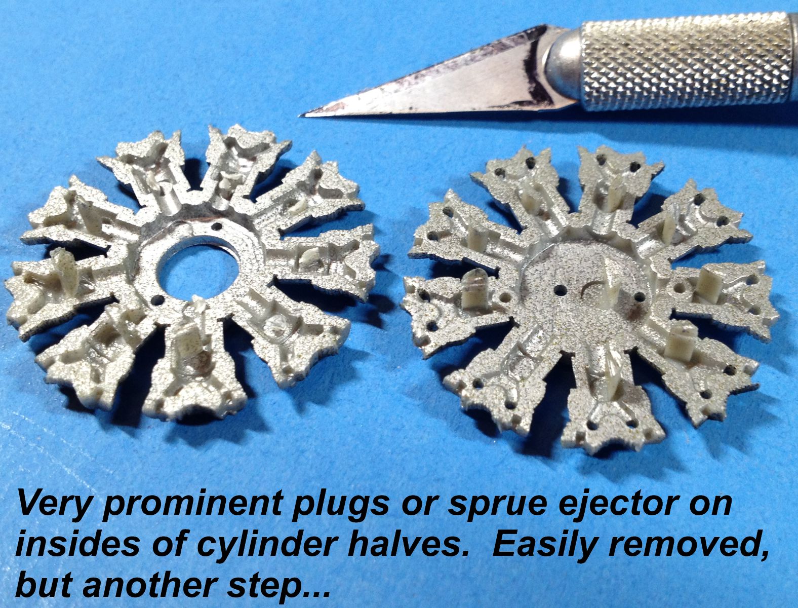
- The mold plugs on the backside of the cylinder halves are very stout. In my preconstruction scrimmage review of this kit, I did not recognize them as “trimmables” but thought they were some kind of line-up aid. By wiggling them with a finger, the plugs broke loose at the bottom and did not interfere with the gluing surfaces
- I recommend that steps 1 and 2 are considered as part location diagrams, not a suggested assembly sequence. There are many small parts, and I found that working from the biggest parts outward produced good results and prevent too much error accumulation. This approach also allows more effective paint touch-up.
- What are the advantages of having so many small parts? I appreciate the detail; I think the engine assembly could be much simpler.
- With so many little parts, when a succession of them builds up into a major assembly, it become very difficult to dry fit to prevent major fit problems later, and more importantly, the problems are much harder to fix later.
- Nearly every pin or receiving socket required a bit of touch-up to fit properly
- Part E57 (all 9 of them) are placed curving inward and down on the cylinder head and part E91 (also 9 pieces) bridges the cylinder heads (p. 13, Bell, 2010).
- Thus far steps 1 & 2 have used roughly 25% of the kit parts.
- Before I attached the engine mount brackets, I jumped ahead in the construction to see how the completed engine line-up was.
Step 3
- Decal 3 is an instrument panel decal with crisp gauge markings. However, since I thought it might be efficient to apply all the other panel decals (numbers 4, 5, and 6) at the same time, I was surprised to find no further references to decal placements of instrument panels. Decal 4 goes on part D7, decal 5 goes on part D10, and decal 6 goes on part C2.
- There are very solid tab-slot connections, but nearly all require a bit of sanding to assemble
- The assembly drawing looked good on a first pass, but actual assembly guidance is a bit lacking.
- I glued the engine mount braces to the firewall with Liquitape to hold the braces but still allow some movement.
- The forward bracket on the machine gun barrel needed to be re-drilled in the correct place to line up with the gun receiver through the firewall. I can’t fault the kit since there might have been some operator error in the complex engine assembly.
Step 4
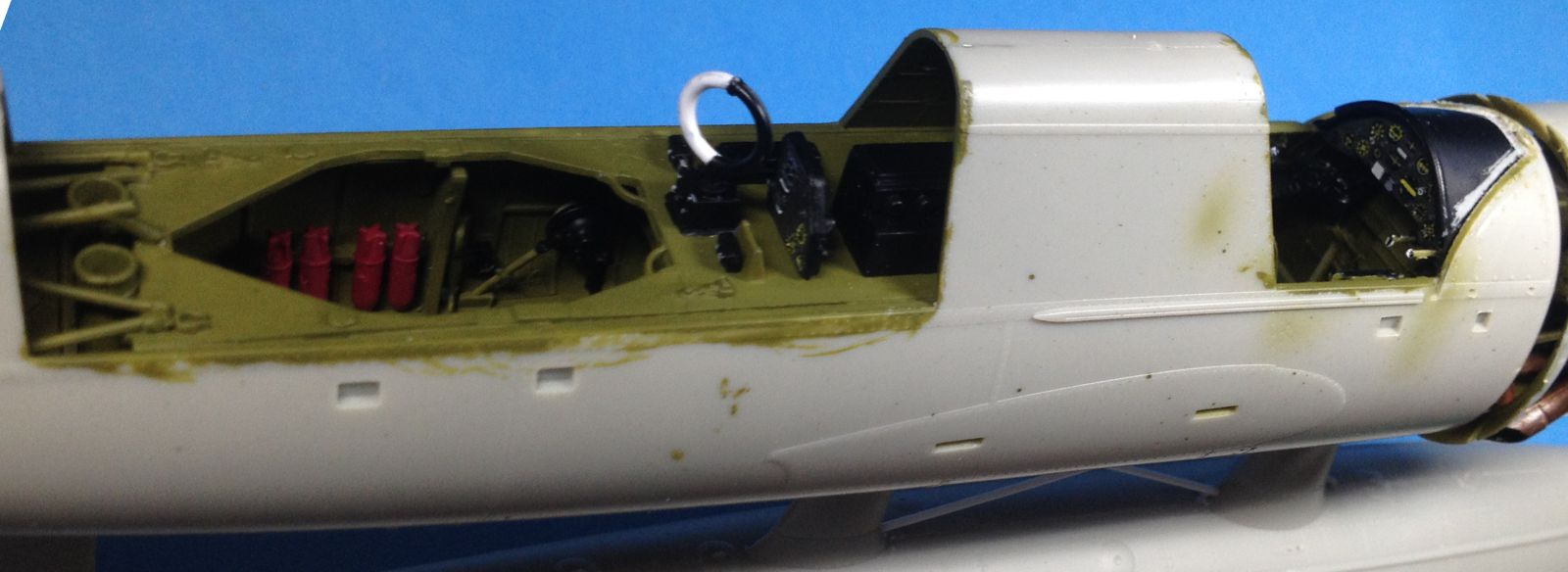
The front office or cockpit starts coming together in this step.
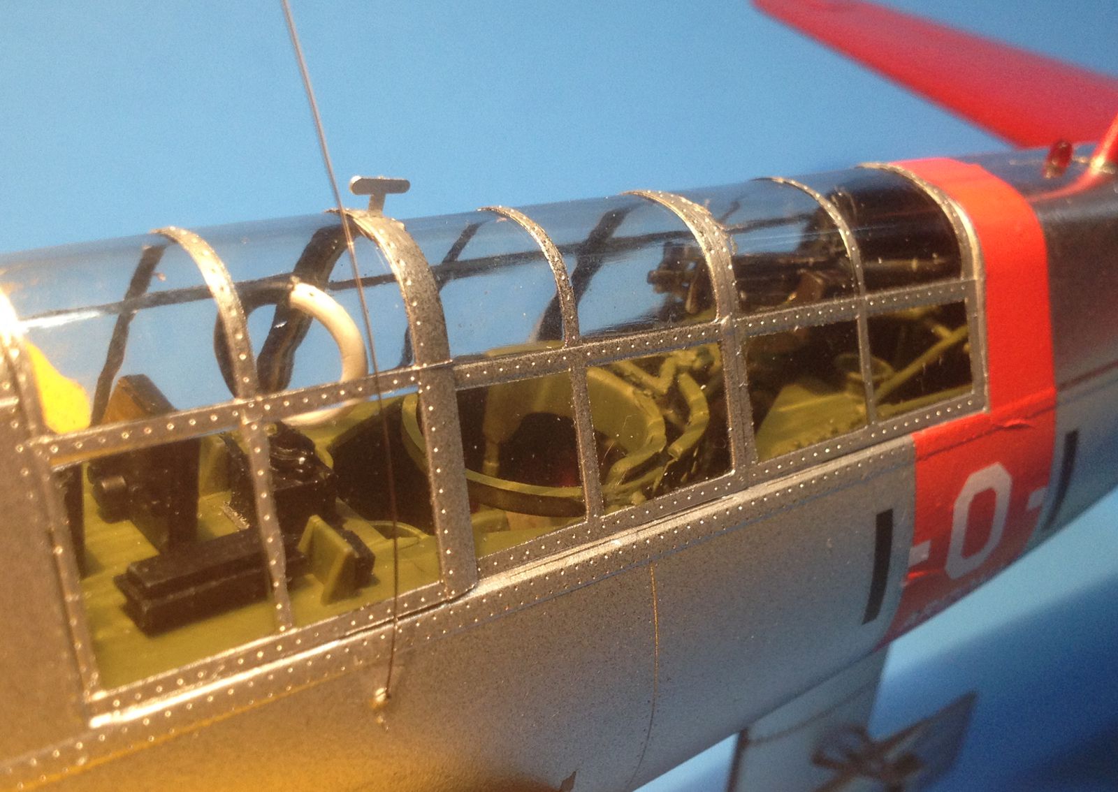
- The PE details are excellent, with separate buckles, lap belts and padding. The belts are very thin with very light etched details. However each belt has 8 pieces. While this makes up into a very nice detail, it seems to be excessive compared to the rest of the kit. I would have preferred more effort directed to the float braces.
- Subtle fit issues, no obvious flash, but I needed to touch up many parts.
- Thin plastic parts, like loops and rod, etc., tended to break when using nippers. Caution needed!
- A lifting cable eye (C61) is included and a bracket (PE 11), but nothing is provided for the lifting cable itself. I put a piece of wire in.
Step 5
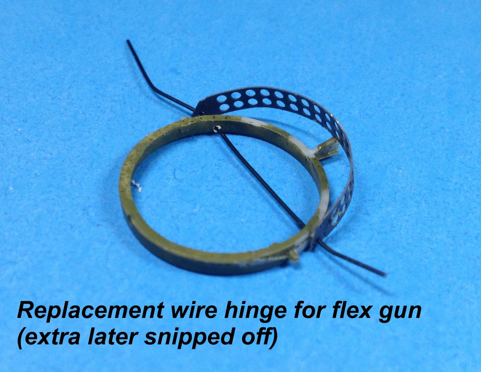
- The rear gun assembly is a little bit tricky.
- C48 and C49 are called for but are identical to C46 and C45.
- Pay attention to the pivot on the cradle, when PE17 and E1/E2 are added to the gun assembly, the instructions show a different mounting location than the next part of step 5.
- E11 does not match to E12, per instructions. The E12 on the sprue is identical to E11. Parts E7, 8, 9, and 10 make up the spare ammo boxes in step 7, so I pulled a box from that step to use here. A vacant spot won’t be unreasonable.
- I did not install the flex .30 cal until after painting.
Step 6
- I drilled out the hinge points in the turret ring. I found that inserting a pivot wire really helped with alignment and was easily trimmed out after gluing.
Step 7
- The bottom of part C54, the rear cockpit deck, had several flash ejector plug-like bits that needed to be removed, similar to what was encountered earlier in the engine assembly.
- Parts C44, C47 and assembly C12-E3 were installed in the next step.
Step 8
- Minor cleanup on the radio box assembly was required.
- Parts E5, E9, and previous step parts C44, C47 and assembly C12-E3 were attached with white glue until final installation in the fuselage halves. A touch of thin CA secure them after final positioning in the competed fuselage.
Step 9
- Instruments are correctly mounted off the rack on small stanchions
Step 10
- The radio deck from step 9 is mounted to the underside of the rear cockpit deck without tabs or locating pins. This did not seem to be a problem at first, but I broke the radio rack off by accident and elected to re-attach it later.
Step 11
- I used the float pylons to determine which drill-outs to use. I only notched them to the bottom of the fuselage for locating the holes after the fuselage halve are together. Once I did this locating, I realized that the float drill-outs are marked with “I” and the wheeled drill-outs are marked with “II.”
- The float flares (D15) have tail caps (D43). I did not put the caps on since they made the flares look bulky.
- I had no problem gluing the foot trough pieces individually in place, as opposed to gluing them up in a single assembly as suggested by the instructions. The troughs were easily placed in the fuselage half.
Step 12
- D3 was used in the previous step and seems to be a typo, but D18 appears to be the same for the left rudder foot trough.
- Many fit problems throughout here, but nothing excessive.
Step 13
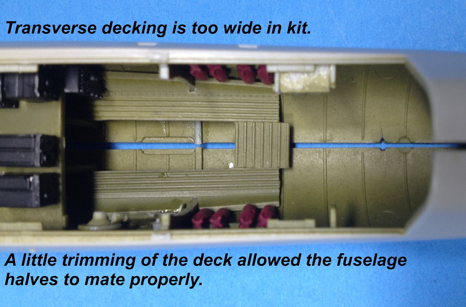
- The fuselage halves are joined at this stage.
- I highly recommend that the radio deck, the rear top deck, the cockpit bulkhead, the instrument panel hood, and the engine firewall be left loose as long as possible, I fitted each subassembly individually and was able to correct fit issues. If I had glued everything into the right half, I would not have had the same success with joining the fuselage halves.
Step 14
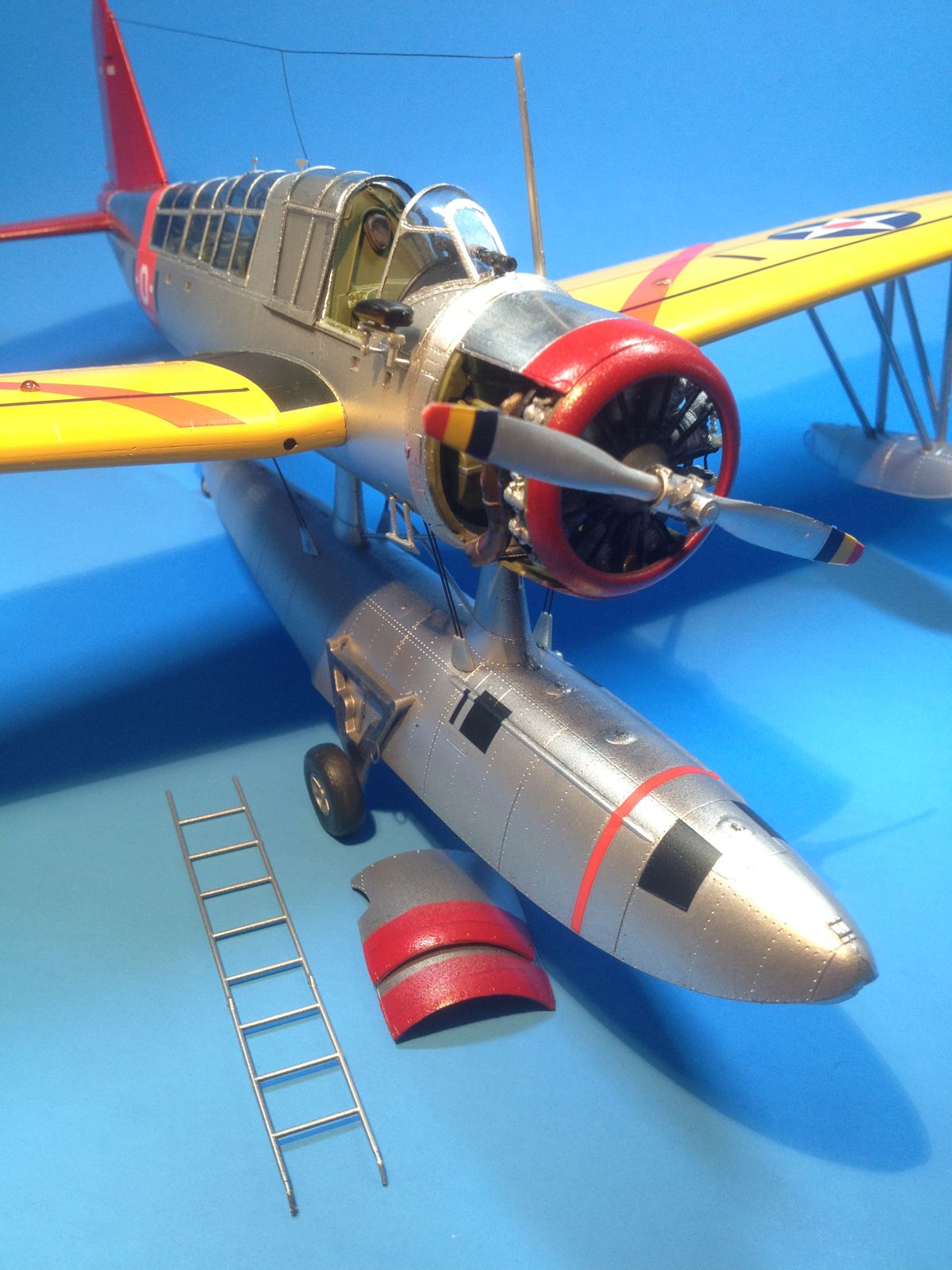
- The cowl flaps were a bit tricky to line-up with the engine mount braces, but the effect after installation is nice.
- The engine assembly still required some tweaking for a reasonable alignment.
- The canopies fit well after a bit of “deflash.”
- A 2-part telescope sight is a nice touch, allowing post-paint installation and more effective canopy masking.
Step 15
- The remaining canopies also fit well after a bit of “deflash.”
- I left all of the other parts off until after painting and decaling.
Step 16
- The prop assembly was a bit finicky and I am not happy with how it looks. The counterweights would have been better done in PE.
- All of the other parts were left until after painting and decaling.
Step 17
- Simple wing assembly, excellent fit after minor trimming and fitting
- Clear parts install from outside, so post painting install is effective. Less masking!
- Wing root fit is very good.
- Trailing edge thickness is reasonable.
- The alignment pins fit snugly into their respective receiving sockets, holding them part together for easy plastic welding solution application.
- No drill out requirements are indicated for mounting the floats, so be sure to drill the locating holes before you glue up the wings. There are no marks on the wing bottom to help with these locations so make sure you do the drill outs from the inside before wing assembly.
Step 18
- Ditto previous
Step 19
- Sprue attachment points are not on the leading edges of the fins or any other joining surfaces. This is a nice feature.
Step 20
- Sprue attachment points are not on the leading edges of the fins or any other joining surfaces. This is a nice feature.
Step 21
- Be certain to dry fit, dry fit, dry fit the wings. I widened all of the receiving slots for the wing tabs.
Step 22
- I did not elect to hang the bombs, but if you do use them, make sure the bomb rack holes are drilled out in steps 17 and 18.
Step 23
- Ditto previous
Step 24
- Ditto previous
Step 25
- Ditto previous
Step 26
- I skipped this step since I did not chose the wheeled version. I did use some of the strut material from this step to extend the float struts in step 30.
Step 27
- The float went together without any difficulty. I did not notice if any drill outs were required from the inside, but in step 30, pins on both ends of parts A40 and A41 suggest that there may have been some holes needed.
Step 28
- The float went together without any difficulty. I did not notice if any drill outs were required from the inside, but in step 30, pins on both ends of parts A40 and A41 suggest that there may have been some holes needed.
Step 29
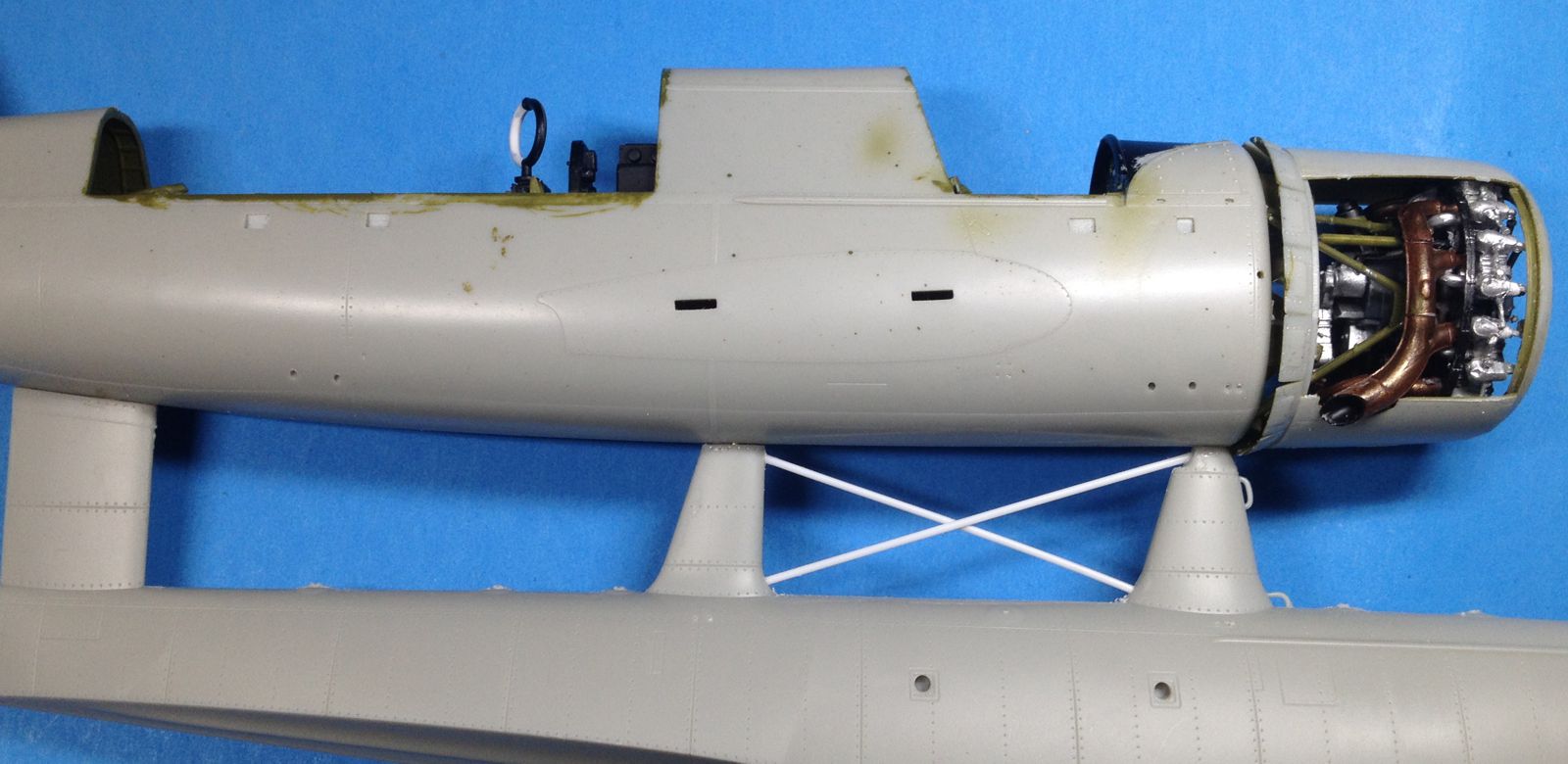
- I used dark annealed 28 gauge wire for float to fuselage braces and plastic rod to replace the larger pylon braces.
- The pylon braces were broken on arrival, so I just replaced them with plastic rod.
- The wheel halves had very prominent plug flash that need to be removed.
- The beaching gear attachment holes on the float needed to be widened a bit, but are very solid mounts for the beaching gear.
- Don’t forget part A50, the hook for the recovery sled!
- The tail wheel looks small, perhaps the fixed gear tail wheel should be used.
- There is no part PE21 on the PE fret I received.
Step 30
- The aft inside brace struts for the floats needed to be lengthened about 1.5 mm to close a gap. I used extra strut material from step 26.
Step 31
- The ladder works well on either side!
References
- Adcock, Al, 1991, OS2U Kingfisher in Action, Aircraft Number 119, Squadron/Signal Publications, Carrollton, TX, ISBN 0-89747-270-5, 50 pp.
- Bell, Dana, 2010, OS2U Kingfisher, Aircraft Pictorial 3, Classic Warships Publishing, Tucson, AZ, ISBN 978-0-9823583-4-4, 72 pp.
- Glidden, Mark, 2005, Long Live the Kingfisher!, Tamiya Modeling Magazine International, Issue 113, March, 2004, pp. 14 – 21


Engine parts
Engine halves

Engine parts

Float wire replacment

Float wire replacment

Fuse halves
Fuse halves
Fuse assembly
Fuse assembly
Gun mount reinforcement
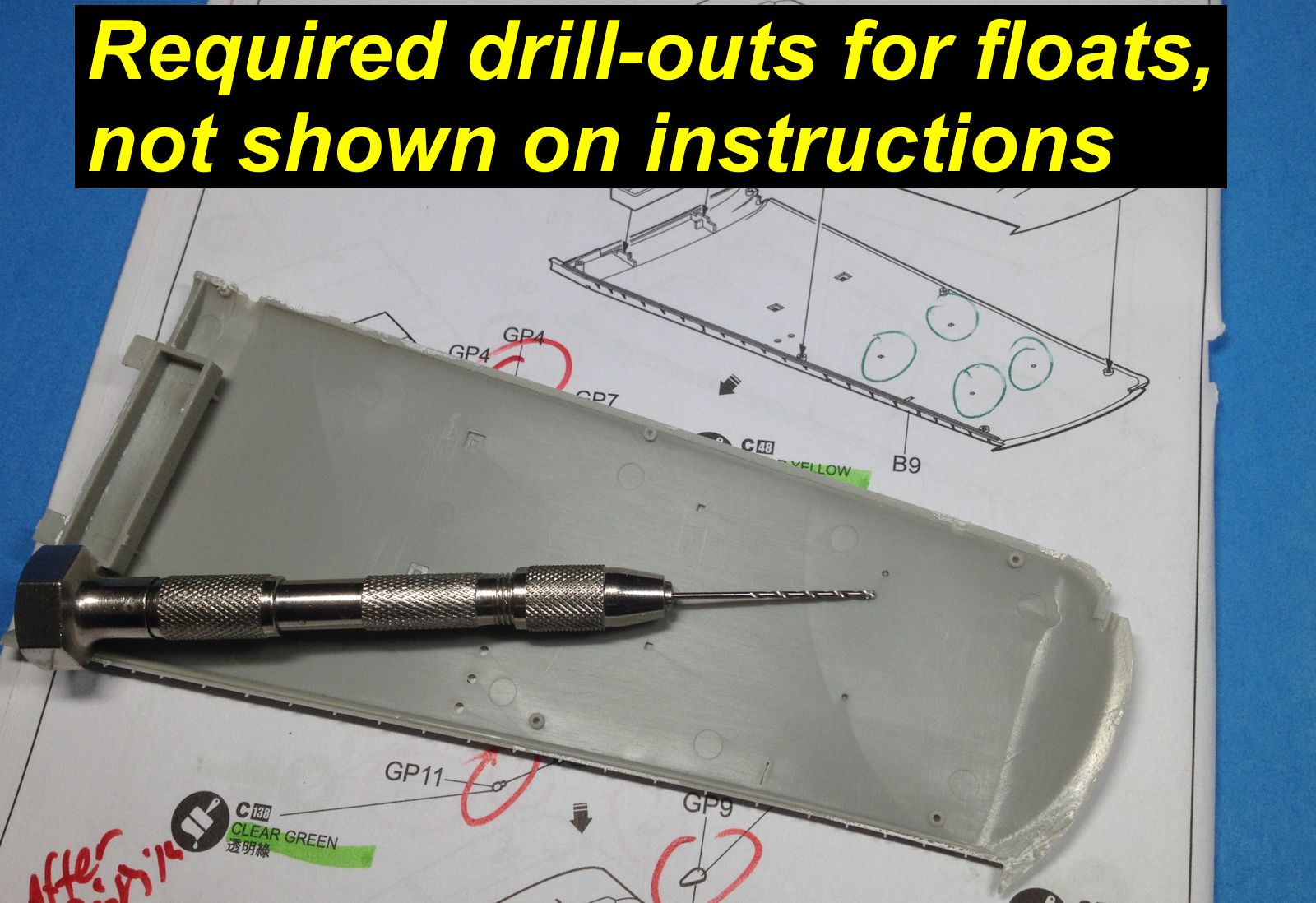
Wing drilling
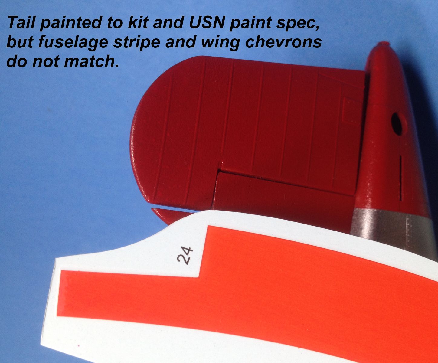
Decal mismatch
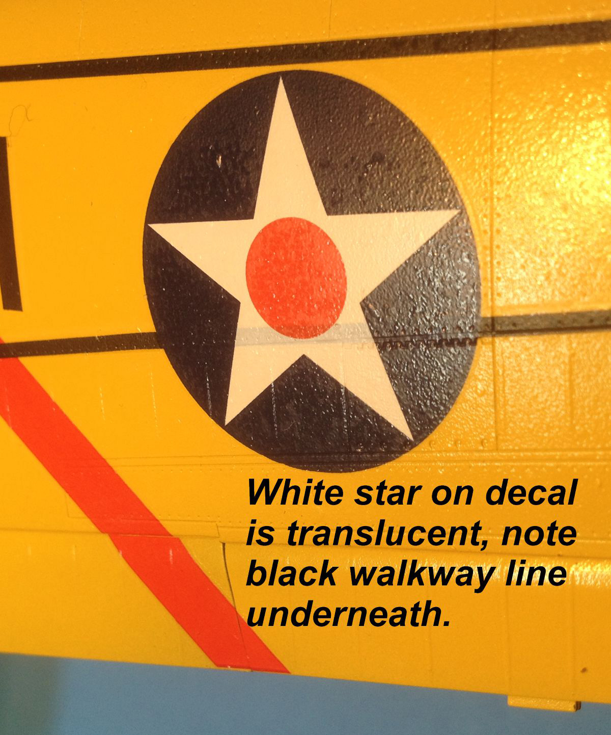
Translucent decals
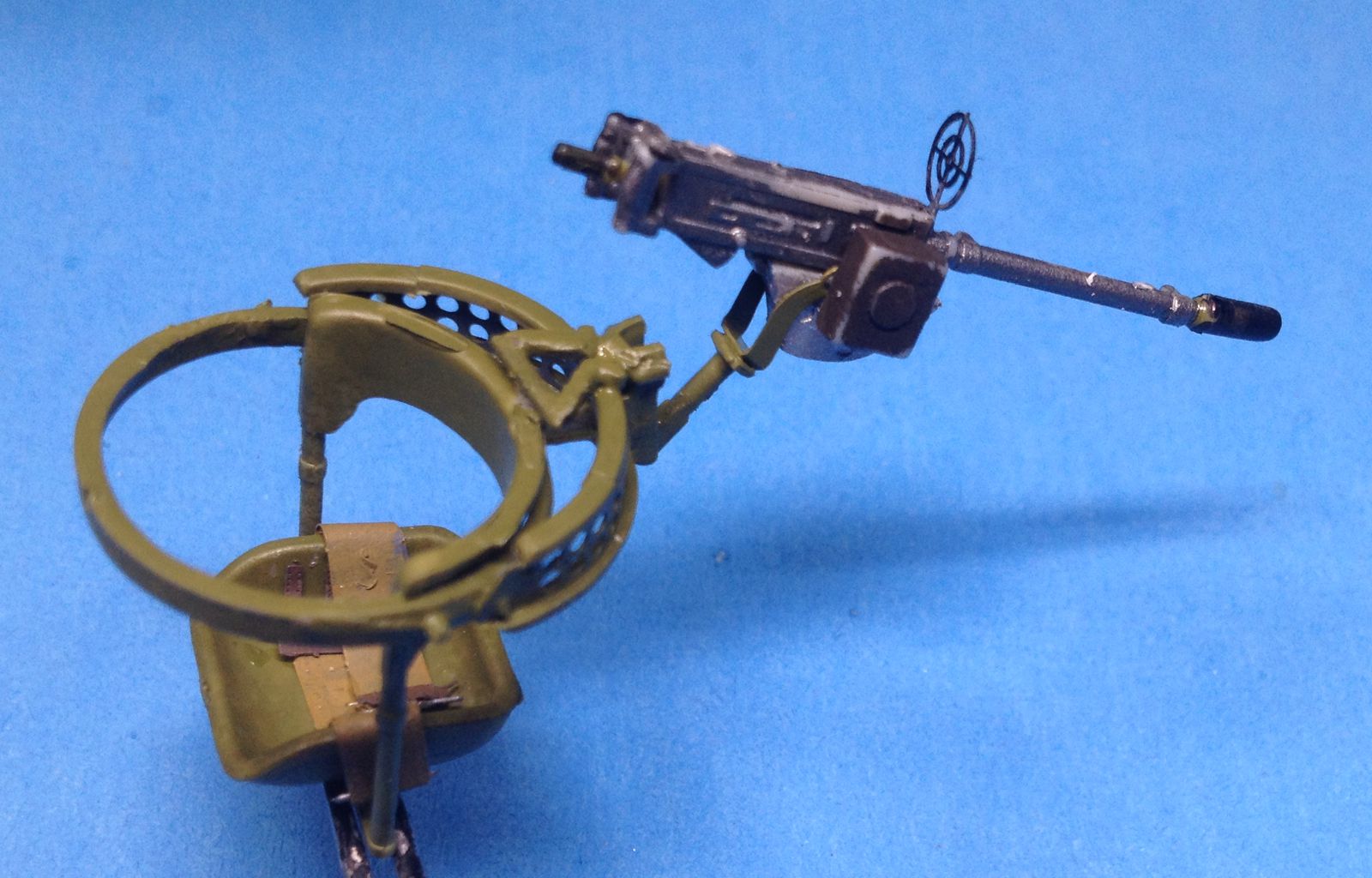
Flex gun assembly
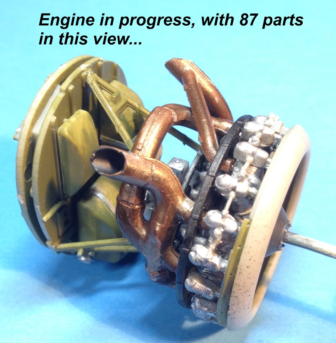
Engine assembly

Flap / Aileron hinge
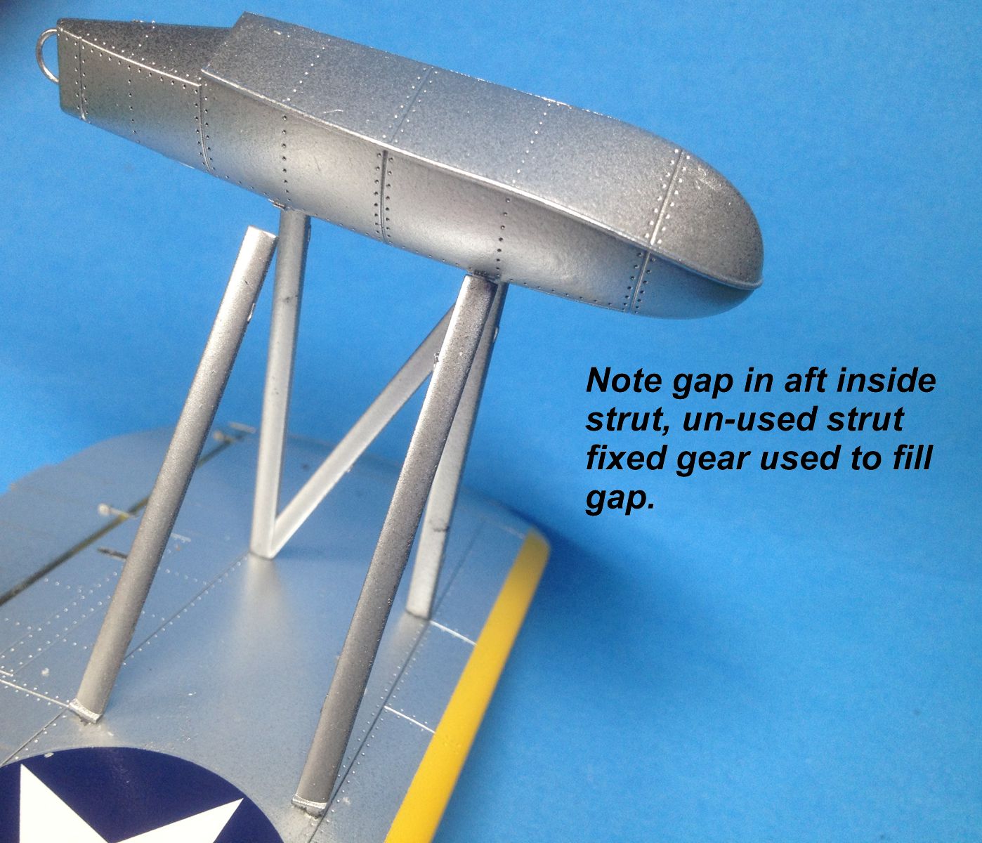
Strut fit
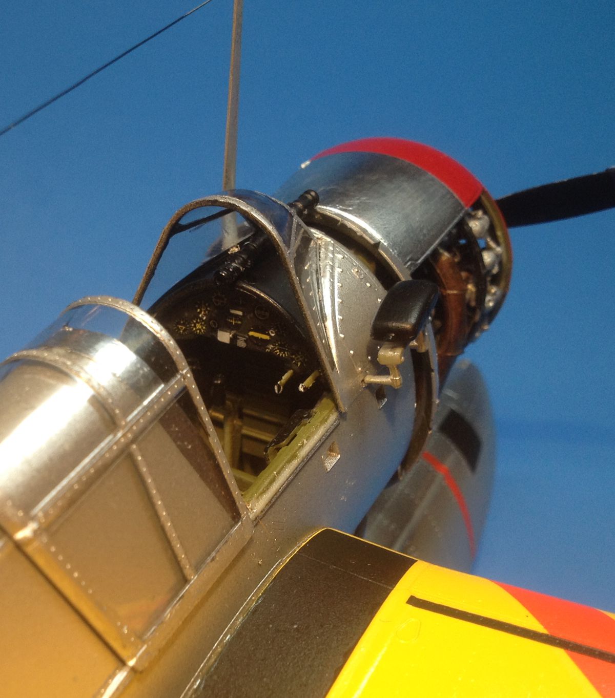
Cockpit
Front view
Front view
Cockpit view

Side view
Side view

Side view
Comments
Add new comment
This site is protected by reCAPTCHA and the Google Privacy Policy and Terms of Service apply.
Similar Reviews