
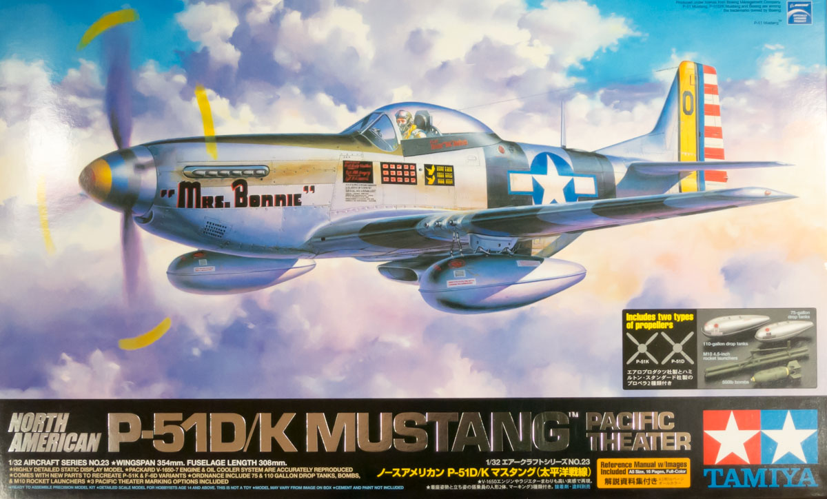
North American P-51D/K Mustang "Pacific Theater"
Background
Much has been written about both the P-51D Mustang and Tamiya’s own take on the famed fighter in 1/32 scale. The “D” model of the P-51 was the most numerous version of the Mustang during WWII, as well as the most refined. During production of the “D” model, over 1000 Mustangs built at North America’s Dallas plant used an Aeroproducts propeller in place of the Hamilton Standard unit, earning them the P-51K model designation.
An additional variant of the Mustang, built off of both the “D” and “K” models, was the fully-armed, photo-reconnaissance F-6D and F-6K, respectively. The F-6D/Ks are distinguished by a series of modifications on the left side of the aircraft: camera ports and an access hatch, as well as crosshatch markings on the wing and canopy.
Tamiya’s 1/32 P-51D Mustang was released to a great deal of excitement and praise; it was heralded as a highly detailed, well-researched and expertly engineered kit. The kit being reviewed here is a new boxing, the P-51D/K “Pacific Theater” edition. Tamiya has added new parts and decals to allow for the building of a P-51D, P-51K or F-6D. The kit still includes working control surfaces and flaps, movable radiator and oil cooler exhaust ports, movable canopy, rotating propeller, removable engine cowlings, removable machine gun covers, and the ability to swap between deployed and retracted landing gear after the model is completed. Although these features may not appeal to all modelers, Tamiya manages to include them without sacrificing the quality demanded by the discerning builder.
Kit Contents
After watching all of the hype surrounding the original P-51D release from the sidelines, I was more than a little excited to unbox this new version. The box was filled with over 20 sprues, although not so crammed as to cause damage. Each sprue was enclosed in its own bag. Additionally, the box had a segregated side compartment that held a tray of the four ultrathin, removable engine cowlings. Below this tray was a box that contained the clear parts, wrapped individually, as well as various magnets, metal rods, screws (and a mini screwdriver!), polycaps, photo-etch frets, and rubber main tires. At the bottom of the box, Tamiya had provided a large black and white instruction booklet, a full-color decal placement guide for the cover plane, a small full-color P-51D history and reference photo booklet, two large decal sheets, canopy masks, and metallic nameplate stickers. Additionally, the kit includes both a seated and standing pilot figure, plus a stand for in-flight display. The kit contains somewhere north of 400 parts, and I found myself blown away by the contents.
For those who have already built the original boxing, an obvious question is what’s new and different about this kit? I spent a bit of time searching through the instruction manual (available online at Tamiya USA’s site) and sprue shot photos of the original boxing to make this comparison. The P-51D/K boxing seems to contain every part from the original P-51D with the exception of the alternate fillet-less tail (Parts C1 & C2 in the original boxing). All of the aircraft depicted in the P-51D/K kit represents planes built after the tail fillet was added, so this is only an issue if you’re buying this boxing to build an early, fillet-less Mustang.
On the “what’s new?” side of things, there are several sprues of parts to cover the P-51K and F-6D. Sprue X contains the Aeroproducts propeller with its specific spinner cover; the K-24 camera; the camera-access hatch in the radiator exhaust-outlet; and the F-6D specific cockpit switch panels. Sprue Y contains alternate spine antennas, namely the twin “Uncle Dog” antennas and a direction finding loop antenna. Sprue AA is included twice, giving enough parts to build two 500 lb bombs; two 110-gallon, long range drop tanks; and two M10 rocket tube sets. The metal 75-gallon and paper 108-gallon drop tanks from the original release are included as well. Finally sprue BB, molded in clear plastic, contains the F-6D camera ports and a K-24 camera lens. New masks are included for the camera ports as well.
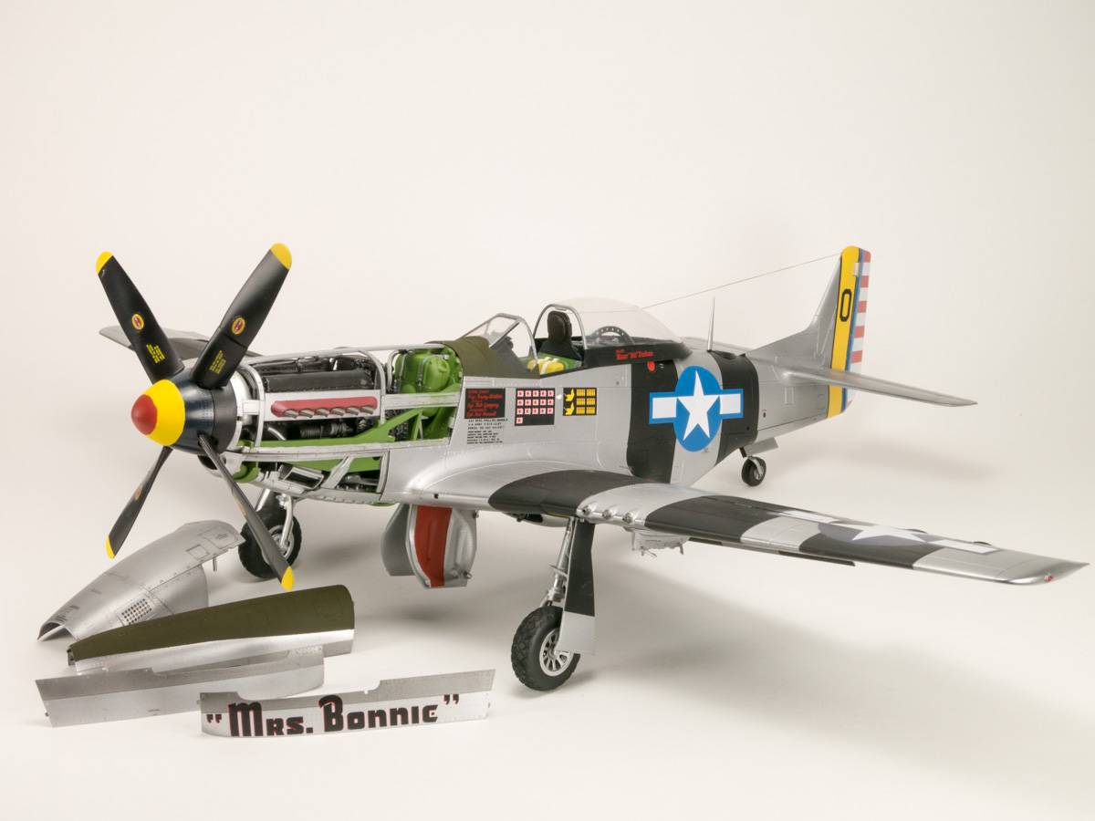
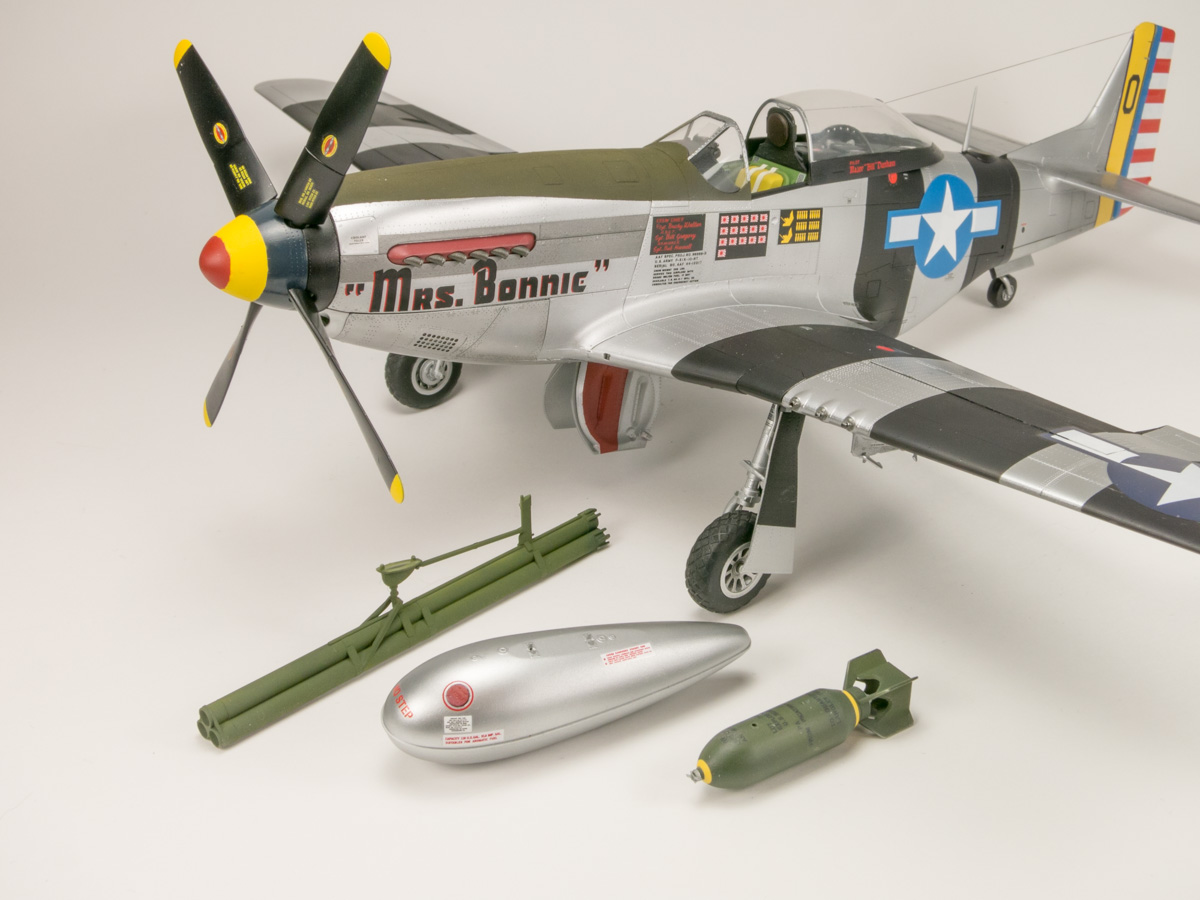
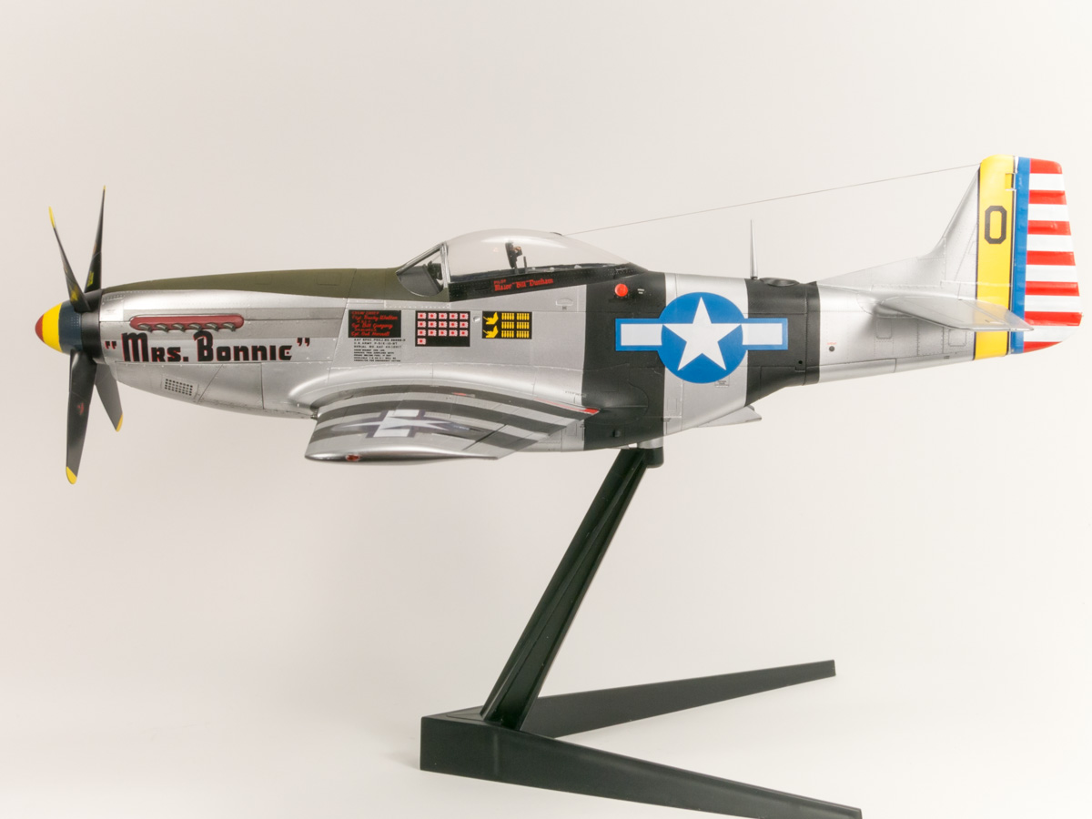
There are three aircraft decal options offered with the kit. The box art aircraft is P-51K “Mrs. Bonnie,” flown by Lt. Col. Bill Dunham, commander of the 460th Fighter Squadron, 348th Fighter Group in January of 1945. A large full-color painting/decaling guide is included for this version of the aircraft. The second option is P-51D “Stinger VII,” flown by Maj. Robert Moore, 45th FS, 15th FG, on Iwo Jima in August 1945. The final option depicts F-6D “Gonzales,” apparently flown by Capt. William Shomo, 1st FS, 2nd Air Commando Group, in 1945 during a mission in which he shot down a bomber and six fighters, winning the Congressional Medal of Honor.
Construction
Before starting construction, I chose to spend some time reading through the 36-page, 82-step instruction manual. Even among the three aircraft options provided by the kit, there is a dizzying array of alternate and optional parts, depending on the exact aircraft being built. Some of the various optional parts are more clearly identified than others, so those building a Mustang not covered in the boxing will need to do some research on the particulars for their aircraft. At this point, it’s best to decide if you will be building with the removable and moving parts. Although the moving and removable parts are well engineered, some of them do not fit precise enough for a contest-quality build. I built this review kit with the working parts, and will comment on them individually as they are assembled. A great deal of time can be saved if you choose not to build, paint and detail parts that you won’t see or swap out.
Unlike the typical kit, the construction of the Mustang starts with the engine. In fact, you’ll build an impressive engine and cockpit joint construction that will be sandwiched between the fuselage halves. The Packard-Merlin engine is a nicely detailed, multi-part construction that lends itself to drybrushing, and just begs for super detailing. Quite a bit of it is visible with the engine cowling removed. The effort will pay off, especially towards the rear of the motor around the carburetor, supercharger and oil tank. A point of caution, the Packard-Merlin engine has its roots in Tamiya’s 1/32 Spitfire kits, and there are a few parts on sprue E and H that are replaced by visually similar, but Mustang-specific parts, on sprue V. Using the wrong parts may cause fit issues later, so double check the part numbers. As the engine provides part of the core structure of the model that will ultimately hold up the propellor and nose structure, it will need to be fully built, even if it’s going to be permanently enclosed by the cowling. There are some smaller detail parts that can be left out to make assembly quicker. Engine assembly also introduces some of the mixed media parts included with the kit. These include the carburetor houses polycaps that are later used to attach the removable lower engine cowling, as well as mounts for a metal nut that is used to screw the engine bay firewall, which ultimately holds the cockpit core to the motor.
Once the Packard-Merlin is finished, the build moves to more familiar territory in the cockpit. The instrument panel is rather cleverly constructed. The panel itself has holes drilled out for each gauge, and a clear part with raised instrument “glass” is inserted behind the panel, leaving the glass flush with the surface. A special decal, printed with the ink facing its back, is applied behind the glass part to provide the face of the instrument. The technique is very effective, and allows for the instrument panel to be painted and weathered with ease, before the glass is present. The panel fits onto the cockpit firewall, which itself attaches to the cockpit floor.
The cockpit floor and aft fuel tank is a single piece molding, and requires some detailed painting. Once completed, the seat can be added. The multi-part seat is very well done, featuring some photo-etch highlights, and includes the option to allow the seated pilot figure to be placed in the cockpit. The pilot will need to be added at this point as it does not seem that the figure would fit in later. Additionally, the seatbelts used will be determined by your use of the pilot figure. Tamiya includes photo-etch (PE) that will be used throughout the build, which in this case includes the seatbelts. The Tamiya PE is very thick, perhaps 3 to 4 times thicker than the typical aftermarket PE. The seatbelts will benefit greatly from being heated by a candle or lighter, and then allowed to cool, before working with them. (This process is known as annealing). For this build, I had the chance to replace the kit seatbelts with a set of fabric ones from Eduard. The fabric belts looked fantastic in the unmanned cockpit, although they might also work with the pilot figure after some modification. A comparison photo of the two belts is provided, and my full review is available as well.
Seating arrangements made, and instrument panel and firewall attached to the floor, the instructions call for mounting the instrument panel shroud. The shroud will house either the N-9 or K-14 gunsight. Both sights are assembled from clear parts, with the K-14 also having a very nice PE cover over the combining glass of the sight. The instructions call for the gunsight, along with the internal armored glass (part L7) in front of the pilot, to be added at this point. I found that both of these fragile items can be left off until just before the windscreen is attached near the end of the build. The radio and electrical equipment housed behind the pilot, and above the aft fuel tank, is added at this point. This is another area for super detailing, as the equipment will be on prominent display under the bubble canopy. Although I didn’t add any wiring, I chose to add some visual interest to the cockpit with a set of aftermarket BarracudaCals cockpit decals. Tamiya provides a handful of prominent decals for the cockpit, but the BarracudaCals set provides nearly 100 decals covering everything from battery placards to small switch labels. A few hours were spent adding them, but the cockpit now pops. During the building and decaling of the core cockpit, I also built, painted and decaled the sidewalls. They are very busy, with a great number of optional switch panel variations to be added, as well as details to be picked out with paint. Although the sidewalls attach to the fuselage, and not the core cockpit, they can easily be added to the fuselage sides after they have been fully finished.
The core cockpit and engine are joined at the firewalls, and then set aside while the fuselage halves are readied. The fuselage halves will each need a bit of preparation before being joined around the cockpit/engine combo. The halves look rather underwhelming out of the box, as the front is the open supports that surround the engine and the rear is molded separate from the tail. The tail pieces are a very precise fit - simply hold them in place, flow in some thin cement, and no one will be able to tell there was a joint there. You’ll also add a series of magnets into the fuselage halves. They hold the engine side cowlings on and the radiator scoop up. The magnets are a clever way to secure various pieces, and although challenging to install (I discovered most of my holding tools are magnetic), they’re held securely with a bit of super glue.
Before the halves join, there is a complex radiator assembly that fits below the cockpit. It consists of various PE radiator screens, a movable oil cooler exhaust vent, and also encloses a metal nut that will be used to mount the Mustang on its stand. (A magnet backed cover will hide the hole when not in use.) It’s a tight fit inside the fuselage, but a precise one. A few final housekeeping tasks are needed before the fuselage is fully joined. If you’re planning to build the F-6D, the two side-camera ports need to be installed at this point. The upper port requires a large hole to be opened in the side of the fuselage, which is then covered with a clear cover. The lower port is a clear part that replaces a small opaque piece of the fuselage. Masks are provided for both ports, allowing them to be installed at this point and remain covered during the rest of the build, until after final painting. Additionally, a pair of magnets is enclosed in a panel above the opening to hold the removable tail wheel enclosure; this part, along with a polycap for the movable elevators, will be trapped between the fuselage halves.
Mating the fuselage halves is fairly easy, but caution must be paid to ensure that all of the internal structures are seated correctly. Test fit, and then trust that all of it fits perfectly and can be secured with only thin liquid cement. The engine fits fairly loose between the fuselage halves once they are assembled, but in the following steps it’s secured more firmly by the various cradles, ducts and hoses that are added. Much like the fuselage, it all fits precisely. If it’s not going together easily, you likely have something slightly out of place.
With the fuselage built, the instructions move on to the wings and control surfaces. Each control surface is moveable, including the flaps. They are each two halves that trap a small metal rod which holds PE brackets that act as hinges when it’s all assembled. The rod is to be super glued into position, while the brackets are to be left free moving. Later, the brackets on the assembled control surface are glued into slots on the wing and tails, allowing them to move. I failed to glue the rod in place within the control surface, and found the surfaces to be a bit too easy to move, perhaps because of this oversight. Instead of brackets, the flaps rotate on pins, which have some additional friction thanks to polycaps trapped in the wing. A polycap in the tail also helps the bracket-hinged elevators move less freely and in unison. The flaps must be put in place before final assembly, as their mounting rods are trapped in place above the radiator scoop, but the rest of the control surfaces can be left off until final assembly if desired.
The wing is molded as a single piece along the underside, with the top halves split in two to accommodate the fuselage. The wing contains the landing gear bay, a large unseen stiffening spar, and machine gun bays. The machine gun bays are very nice with both the guns and ammo belts represented, although the “closed’ removable covers do not fit particularly tightly. A second set of covers is provided, which can be cut apart to depict the “open” gun bay covers. If you’d rather not have this removable feature, the covers would attach very cleanly with the aid of some glue. As I intended to keep the removable cover option, I used a bit of blue tack to hold down the covers when closed. If you’re going to skip the opening bays, you’ll still want to use the bay structures in the wing (parts W11 & W10) as they provide some detail to the spent cartridge chutes that exit on the underside of the wing.
The landing gear bay is notable as the worst instance of visible ejector pin marks, which is only because of the degree to which they appear on the back of parts, or end up masked by other parts, elsewhere on the model. This attention to detail is a testament to the quality of the kit, and is not the only noticeable modeler-friendly sprue design feature. Many of the parts are attached to the sprue on their mating surface, meaning you won’t destroy any of the fine surface detail while cleaning up attachment points! That said, there are some very difficult areas on the roof of the bay to remove the ejector pin marks, as there is a lot of surface detail that can be destroyed. The ejector pins on the spars that are added to the bay are fairly easy to clean up, as the spars have no major detail to speak of. It’s certainly something that will need to be done on a contest quality build, but it’s genuinely the biggest fix needed on the whole plane.
The temptation may be to attach the wing tops after the fuselage has been mated, but the kit is so well engineered that this will likely cause more trouble. As a cautionary tale, I built my wings fully, test fitted several times to the fuselage with perfect results, and then made the mistake of using an extra thick super glue to hopefully add some strength to what I assumed could be a weak, but important joint. The slight thickness of the super glue actually ruined the precision of the joint. I was forced to remove the wings, scrape all of the super glue off, and then refit using liquid cement. The joint is now strong and perfect (except for a few areas I botched up because of my super glue misadventure). I would be surprised if anything more than a very tiny amount of filler would be needed to create a perfect wing root joint. Once the wings are attached, you’ll need to add the radiator scoop below the wings. This will require a great deal of careful work to assemble and attach without destroying the fine rivet detail present on the scoop and where it meets the fuselage.
Before moving on from the wing, you’ll likely want to make a choice about the removable landing gear. As the plane is designed, screws hold the landing gear struts in their deployed position, and the attachment point and screws are covered by a removable piece of the leading edge of the wing (parts A11 & A12) with a magnet attached to the back. Although it’s very well designed, it’s not a perfect fit. If you’re building the kit with fixed gear, you’ll likely want to attach the parts for your option (landing gear struts for gear down or one-piece gear door for gear up) and then permanently glue these leading edge covers in place before painting. The same would hold true for the tailwheel. The entire gear assembly and bay is removable, along with a piece of the lower tail. The fit is good, but again not perfect. For fixed gear, you’ll want to permanently mount the assembly so the exterior tail part can be glued in (and perhaps filled a bit) for a better joint. A final note for those with Advanced Modeler Syndrome, the large main gear bay doors can only be built in a fully open position with the landing gear deployed. This is correct for an aircraft that has been powered down for more than a few minutes, but an aircraft running on the ground, or in the air with gear down, would have these main gear doors retracted against the fuselage, which would require some amount of scratch building, likely using a combination of both the open and closed gear door parts.
The main landing gear struts are fairly detailed, depicting brake line and the movable hinge for the smaller main gear doors. The main struts seem very strong, but they enclose two metal rods for added strength. Once closed around the metal supports, the struts will need a bit of sanding and filling before adding the delicate detail parts. The main tires are actually made of a soft “rubber” material, but they are marred by a nasty seam running across the center of the tread for the full circumference of the tire. This proved nearly impossible to remove. I tried a sharp hobby knife, photo-etch scissors, sharp sprue cutters and finally, sandpaper. Taking off as much as you could with the cutting implements and then sanding worked alright, but the sandpaper grit required to remove material from the rubber quickly started to eat the tread. The results were okay at best, and many other modelers have turned to resin replacement tires to deal with this issue. The wheel rims were very nice, split side-to-side, enclosing the tire as the rims are joined. The molded-in hub press fit tightly into the strut hubs, while still allowing for the wheels to rotate. The tailwheel tire is a one-piece, standard plastic part that fits onto a hub molded into the rear strut (which is also re-enforced with a metal rod).
With the wings attached, the build is in the home stretch. The engine cowlings can be readied. To allow them to be removable, the side cowling panels are backed by a bit of PE that clings to a magnet inside the fuselage. The top cowling is held in place by gravity and small tabs that fit between the firewall at the rear and spinner at the front. The bottom cowling is held on by a combination of magnets and metal pins that press fit into the carburetor. The underside of the engine features some carburetor ducting that will not fit behind the lower cowling; the ducting is held tightly in place by a magnet, and can be easily removed when fitting the cowling. The propellor and spinner can be assembled and installed at this point, or left off until the end. The assembled propeller and spinner press fits onto the engine's output shaft with the help of a polycap, although I was not impressed with the fit. If not using the removable cowlings, which require a bit of play in the spinner to remove and install them, I would highly suggest installing the lower half of the spinner, getting a good fit with the polycap and output shaft, and then gluing them tight before attaching the propeller and upper half of the spinner. As mentioned at the beginning of the review, there are two separate propeller and spinner assemblies, the “K” model specific Aeroproducts and the standard “D” model Hamilton Standard. Both are very well done, although the blades are attached to the sprues on the surface of the propeller, requiring some careful removal and cleanup. The separate spinners also make painting a breeze.
Tamiya provides masks made of Tamiya tape for all of the glass parts, although unlike aftermarket masks, they are not pre cut. However, it’s not difficult to cut them out with a sharp hobby knife or fine scissors. The windscreen is a large clear piece that also includes a portion of the fuselage. The size of the part allows the windows to be masked and the part to be attached to the fuselage with your regular glue, all without fear of of leaving glue marks on the window portion, another well-planned feature. If you left off the gunsight and armored glass earlier in the build, be sure to install them before the windscreen.
The sliding bubble canopy is provided in three versions, and are called out for specific aircraft in the instructions, but otherwise unlabeled. They appear to represent the “early” canopy (part P1), “late”/“California” canopy (part N1), and “Dallas” canopy (part M1). Each canopy has a mold seam running its length that will need to be removed. Be very careful when working with the canopies, as they seem to be more fragile than the smaller canopies I’m used to working with in 1/72 scale. I managed to crack the appropriate canopy for my build while polishing the seam, and was forced to substitute one of the others.
The spine of the aircraft, just aft of the cockpit, is installed separately. This allows for an alternate spine with a camera access hatch for the F-6D. Tamiya suggests that you install the bubble canopy into its track before installing this spine. If you’d prefer to wait until after painting and decaling, you can slightly sand down the canopy mounting pin (part D33), to allow the canopy to be installed and removed by turning it 90 degrees to the side. In any case, the spine will need to be carefully installed before painting as it is an extremely precise fit. It can be placed a hair out of alignment to either side, which will require some sanding and filing, so take your time.
At this point, the model should be ready for painting. Many parts (and the few decals called out during the build) can be selectively left off until after painting. I chose to leave off the elevators, rudders, antennas, exhaust stacks, canopy and a few other parts until the very end.
Although I decided not to add ordinance to my Mustang, I did assemble the new drop tanks and weapons. The 110-gallon tanks are two halves, split at the real articles seam, making for easy assembly. An array of decal stencils are provided for the drop tanks, as well as the 500 lb bomb. The 500 lb bombs are easy to assemble, with the rear fins molded into the two halves of the bomb. Photo-etch is used for the spinners on the front and rear of the bomb. The M10 rocket tubes, basically a bundle of three individual bazooka tubes under each wing, are fairly nicely done, but would require a bit of seam filling along the length of the tubes, as well as the endcaps. The rocket specific underwing mounting brackets are molded into the M10. The drop tanks and bombs are attached to the standard underwing hard points, and include sway braces that are specific to the new ordinance, although the 110-gallon tanks do not include the additional wooden sway bracing that seems to have been used on some operational aircraft.
Painting and Decals
I chose to build the cover plane, Lt. Col. Bill Dunham’s “Mrs. Bonnie.” It’s a rather colorful aircraft that features large black stripes on the fuselage and wings. It’s covered in a full-color painting and decal placement guide. Although the instructions cover “Mrs. Bonnie” in January 1945, I chose to build based on photos as it appeared after Dunham had scored his 16th kill in August 1945. Interestingly enough, the provided decal sheet includes an unreferenced 16th kill marking (decal #148) that can be added to the referenced other 15 kill markings (decal #147). Beyond this decal, there are a few other changes that will need to be made. By the August 1945 photos, the Aeroproducts propeller had been swapped for the Hamilton Standard, and the spinner was painted red/yellow/blue/black. The kit specifies red/yellow/black/silver, but I was unable to find any early reference photos to confirm this scheme, although it’s very possible that when the propeller was swapped, the stripes were also redone. The exhaust shrouds also seem to have been painted a red or pink color (perhaps heat/sun faded Insignia Red?).
As I built my Mustang with the working features, I switched it to “gear up” mode, which effectively masked off the main landing gear bay. I also used the masked canopy, secured shut with a bit of white glue, to mask off the cockpit. I chose to paint the plane in Alclad II Aluminum, therefore I needed a perfect glossy surface to paint over. I primed the Mustang in Tamiya Gloss Black and went to work on the small amount of body prep work needed. The fuselage joint immediately in front of the windscreen needed a bit of filler and sanding to ensure a clean joint as no panel line exists there on the real aircraft. Similarly, the seam running from the radiator scoop inlet to the radiator exhaust needed a bit of work, as well as the seam at the bottom of the tail. The leading edges of the wing needed very little work at the seams; a few swipes of a sanding stick made the joint disappear. With the bodywork finished, a second coat of primer was added to inspect the results. Happy with the outcome, I applied the Alclad Aluminum with light mist coats. The paint was rock hard overtop of the black undercoat, and it was safe to mask off for the semi-gloss black stripes on the wing and fuselage. I painted this with Testors Acryl. The green anti-glare panel was masked off and painted with Tamiya Olive Drab.
Although Tamiya provides decals for the spinner, I was using a different arrangement of stripes and masked the spinner off, painting it with Insignia Red, Yellow, Blue, and semi-gloss black. In retrospect, the Insignia Blue on the spinner likely should have been a much lighter color, matching the unique bright blue insignia decals and tail stripe.
With the paintwork finished, the decals were next up. Tamiya decals have a bit of an iffy reputation that seemed to be confirmed here. The decals were very thick, and the large ones were especially fragile. I choose to apply them directly over the Alclad without an overcoat hoping to preserve the great look, but the thick decals made this a poor choice. If I used the kit decals again, I’d be sure to use a gloss or Future coat before applying them. Despite being thick, the insignia decals were sadly see-through when the white areas were applied over the black stripes. The larger decals also had a great deal of trouble settling down over the surface of the model. Specifically, the upper wing insignia would not settle down over top of the surface ribs. It needed to be slit along the rib and then forced down when somewhat dry with a Q-tip dipped in Micro Sol. I used this Q-tip technique to settle down the rest of the insignia, along with the red, white and blue rudder decals. The tail decals proved very fragile, with small bits breaking off at the edges, instead of conforming to the contours at the top and bottom of the rudder and tail. They were easily touched up with paint, but with the size of the rudder in 1/32 scale, I wish I had masked the pattern off and painted it.
The small stencils, unique kill markings and the “Mrs. Bonnie” name all went on easily, which was a stroke of luck. The decals being such a mixed bag, I’d likely choose to use an aftermarket set if I was building the kit again. This was the the only real disappointment in an amazing kit. The build was finished by attaching the few parts left off, opening up the canopy, and removing the window masks.
Conclusion
Building Tamiya’s 1/32 Mustang was an amazing experience, and the “Pacific Theater” boxing offers a new array of parts to help make any World War II Mustang a reality. Although not 100% correct in every aspect, it is perhaps the most accurate model I’ve ever built in terms of the optional parts offered to change the aircraft to suit the prototype you’re building. The kit also has a broad appeal to modelers of nearly any level. The working parts appeal to those into model building purely for the fun; and the supreme detail, engineering and opportunity for scratch building will appeal to even the most advanced modeler. The kit will take some time to put together, due mostly to the large part count. However, anyone with a few builds under their belt should have no major issues with the construction, which is complicated only due to the large assemblies and the unforgiving nature of precisely fitting parts that might not be so precisely assembled.
The bottom line is that this kit is an amazing experience. Some of the early hype promised an almost perfect kit, a contest winner in a box. The truth of the matter is, just like any other kit, you get out of it the time, skills and efforts you put into it. The specialness of this kit is that it doesn't fight your efforts. It’s designed to go together without issues, and this encourages you to step out of your comfort zone, try a new technique, add a few details and just have fun building it. The kit is worth every penny of its admittedly large price of entry, and will likely be a build I remember forever . . . one that I cannot wait to try again!
My many thanks to Tamiya for providing this kit for review, as well as to IPMS/USA for the opportunity to review it.
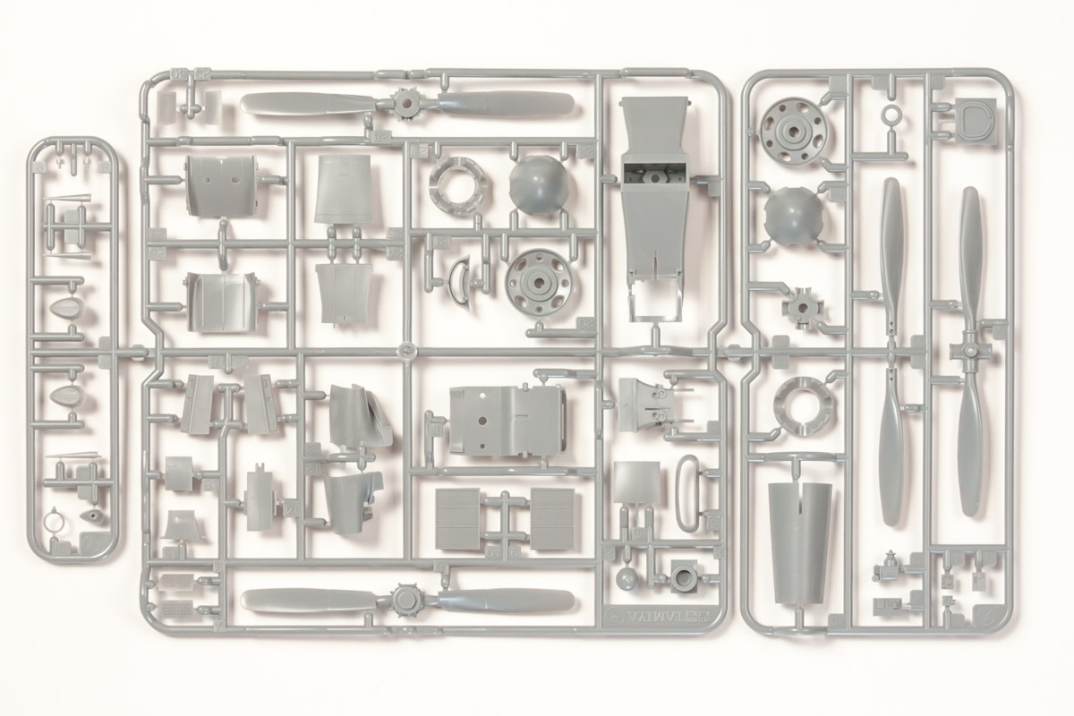
Sprue R, X and Y- New

Sprue AA
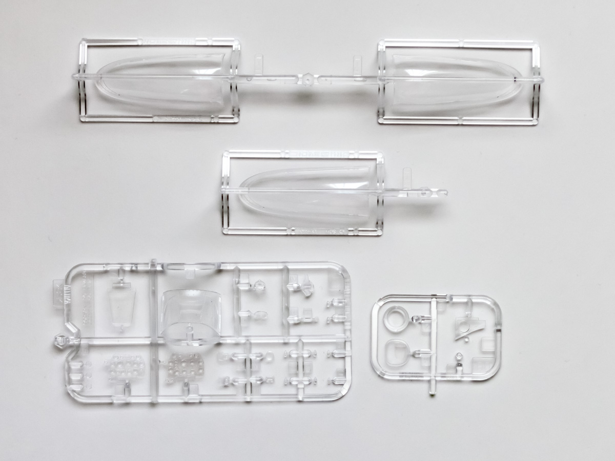
Sprue BB

Decals
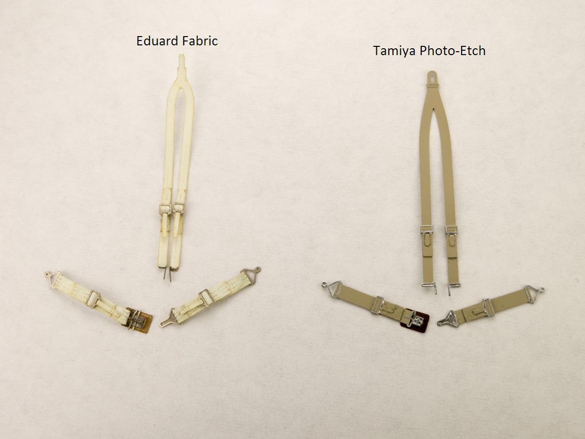
Seat Belts
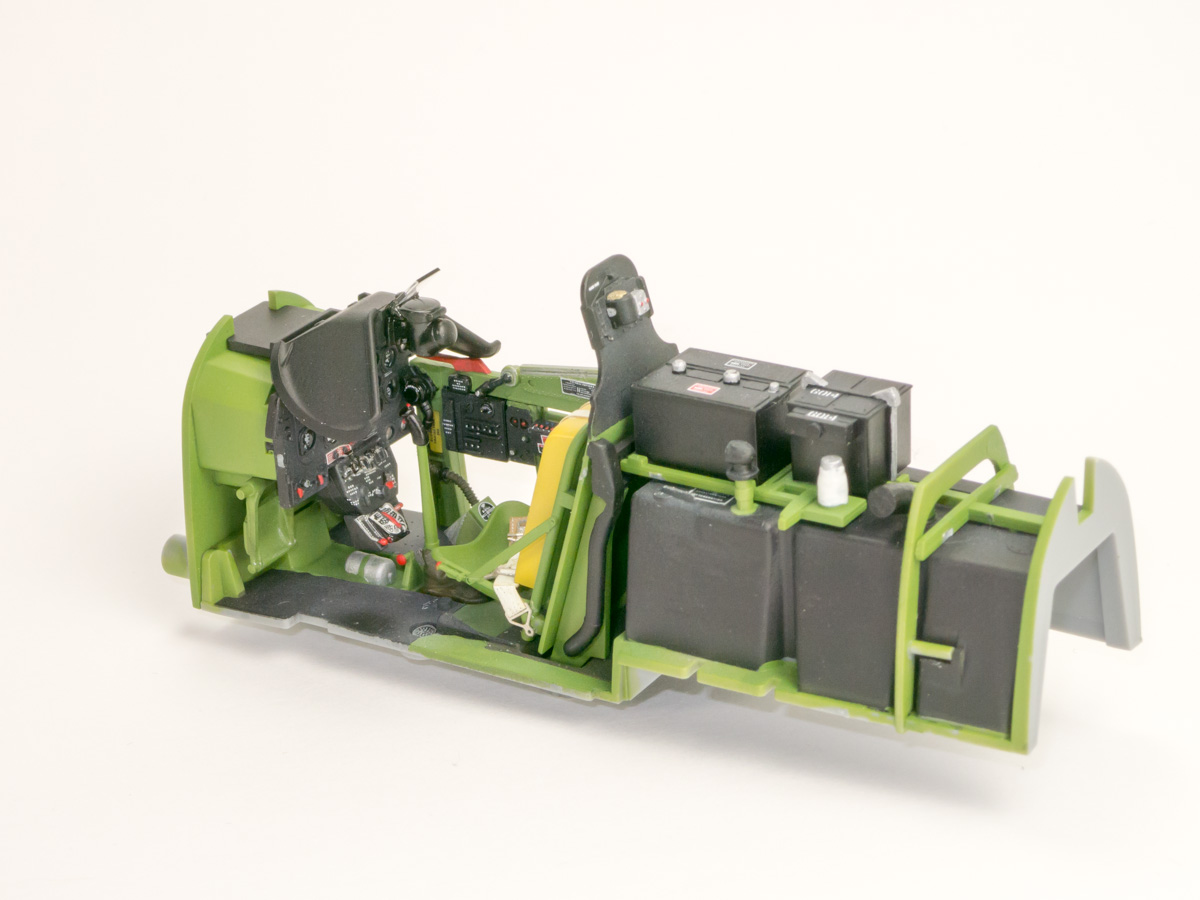
Cockpit Right
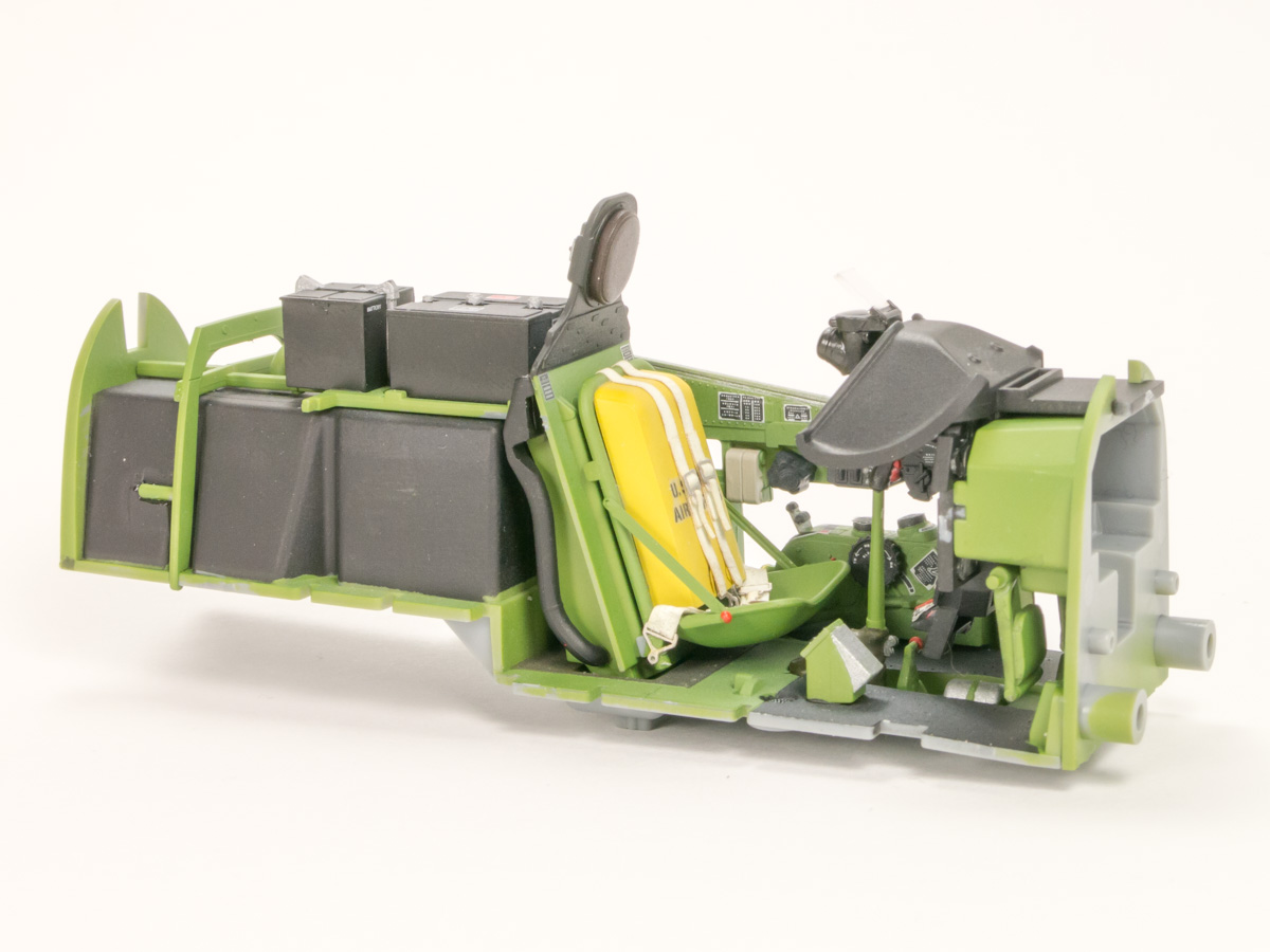
Cockpit Left

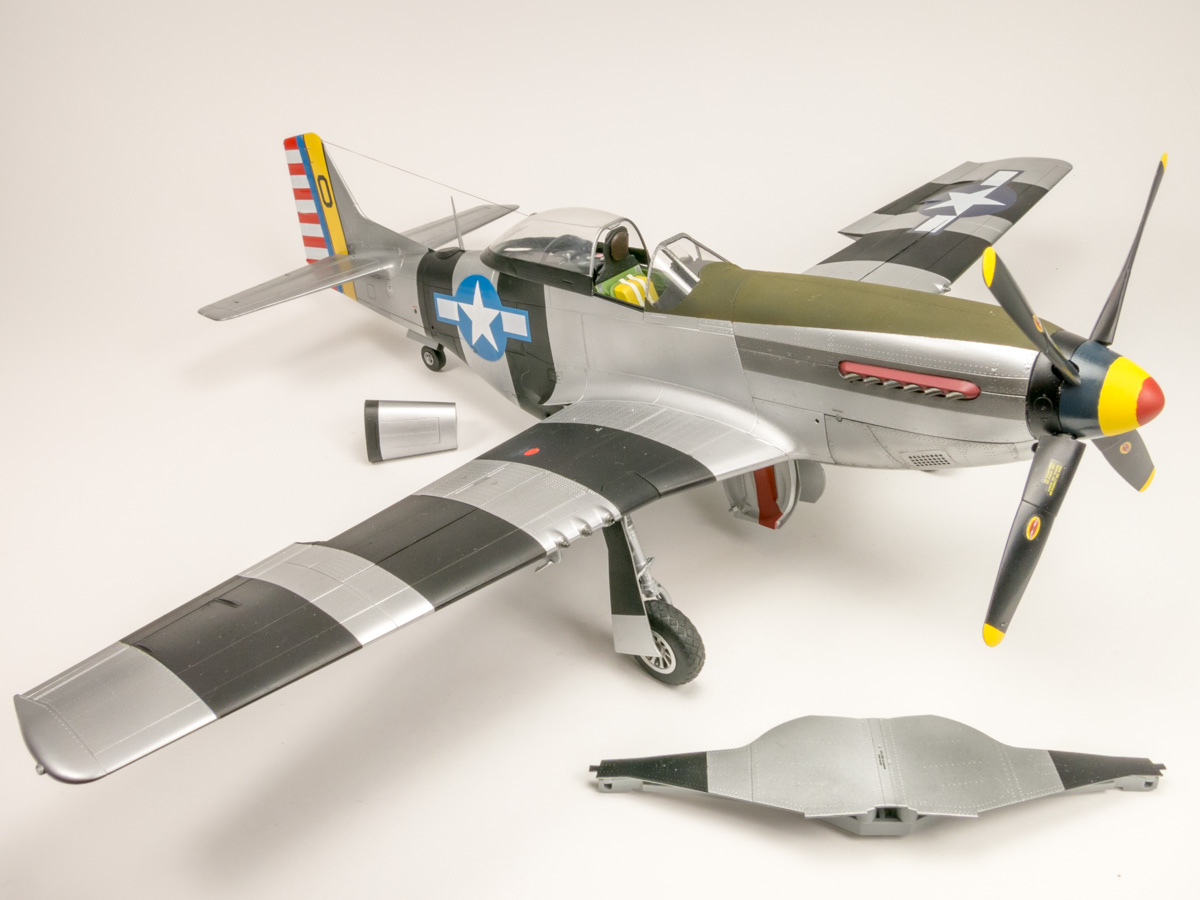
Finished Left
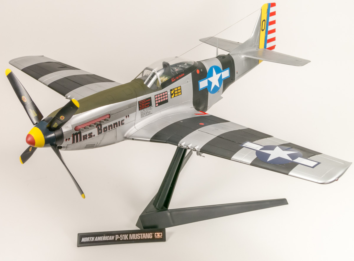
Finished Stand
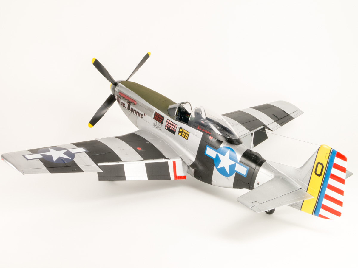
Finished Right Rear
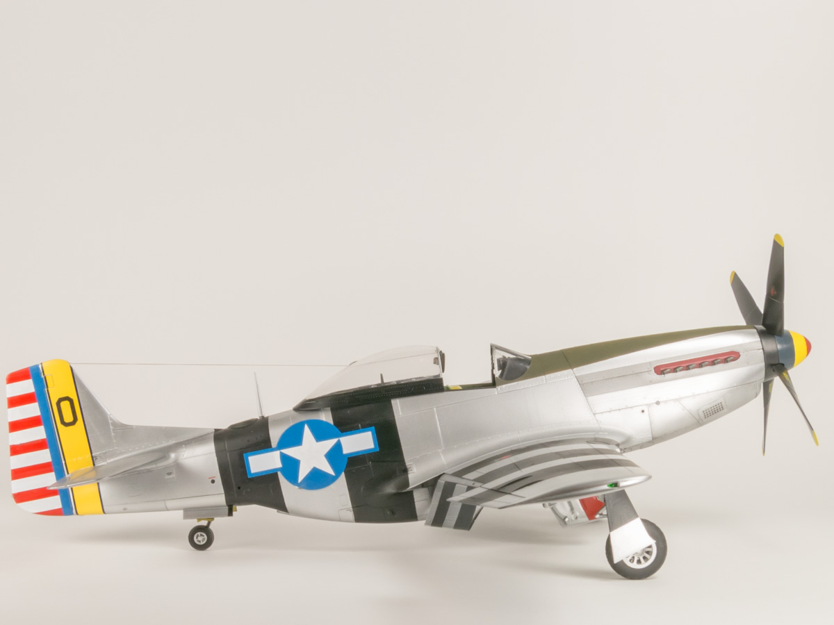
Finished Side
Open Cowling
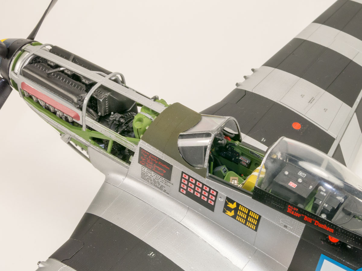
Cockpit and Engine

Gun Bays
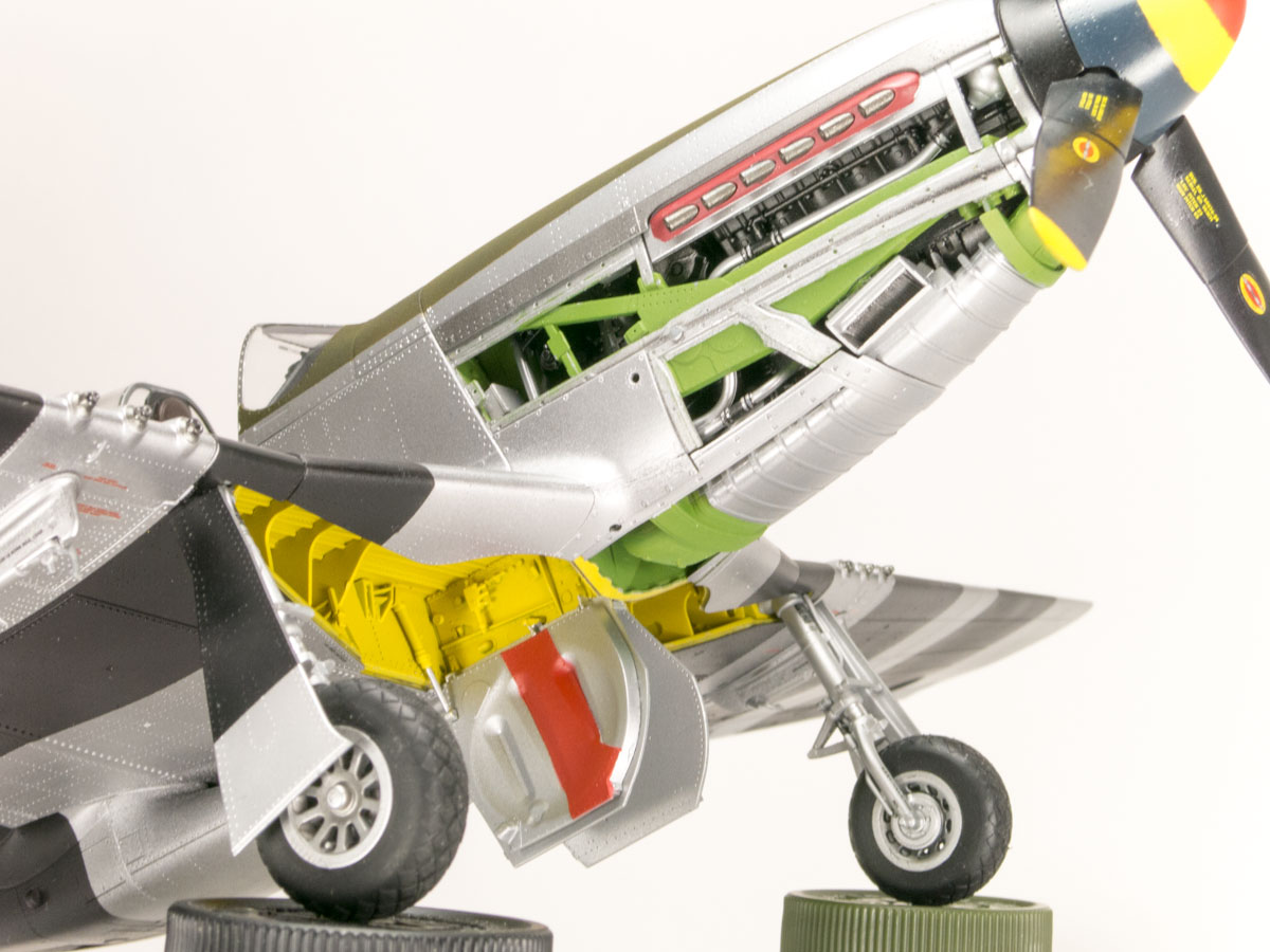
Engine and Landing Gear bays
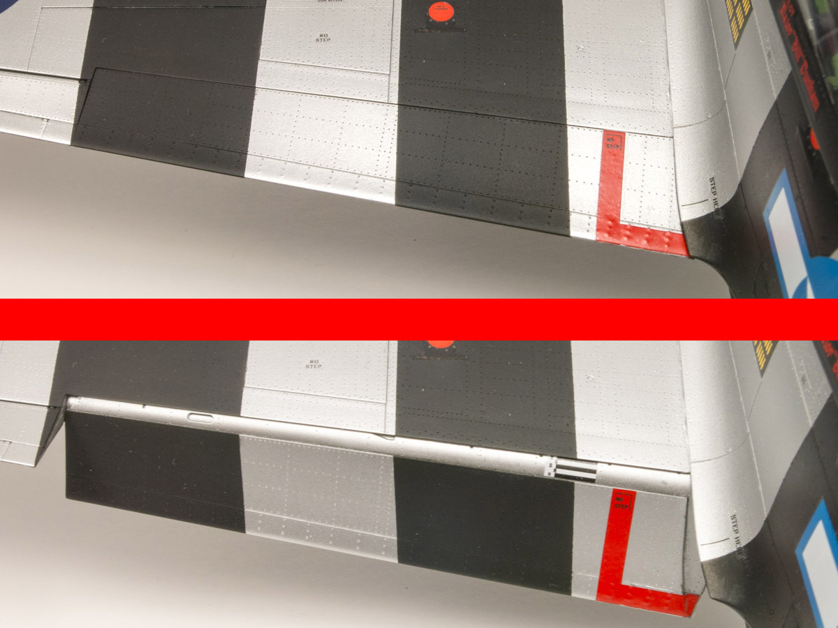
Positionable Flaps

Positionable Control Surfaces
New Stores
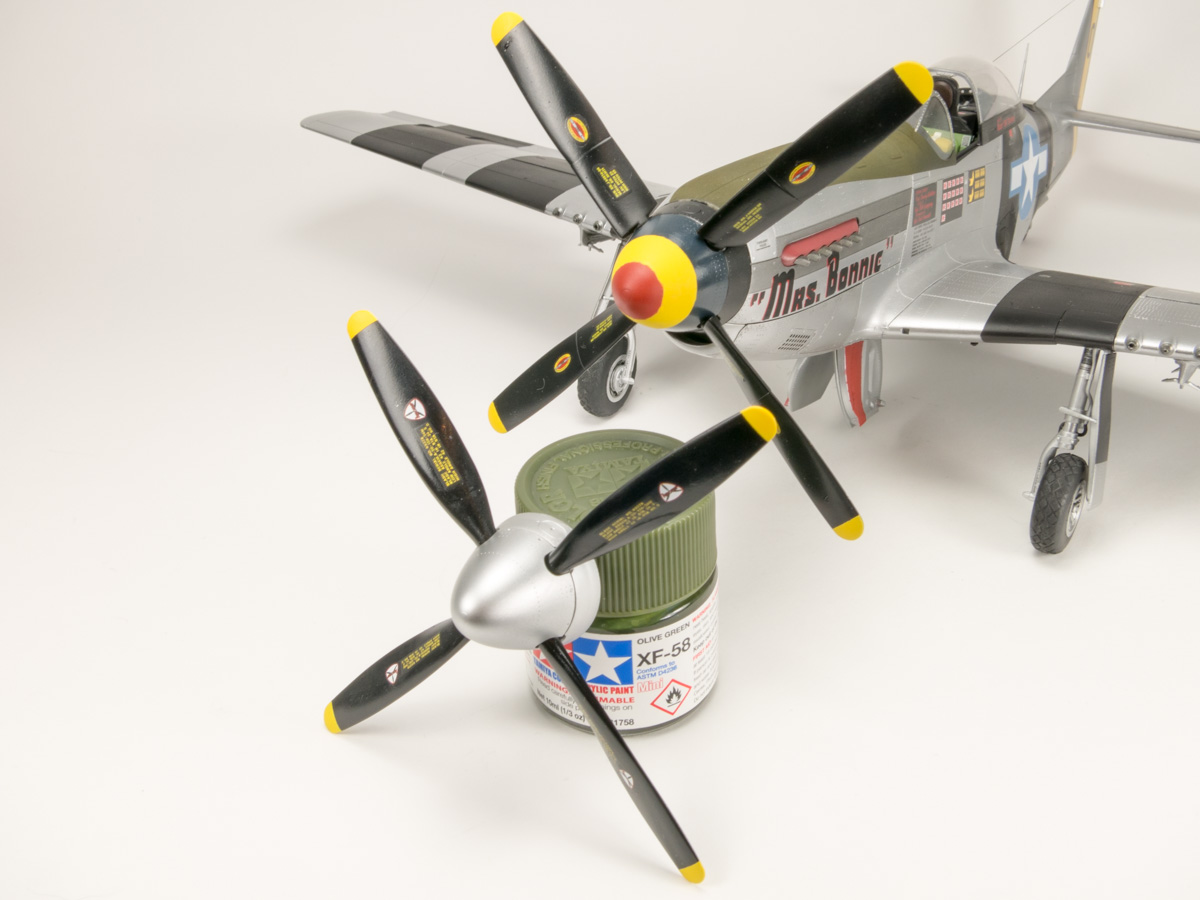
New Prop
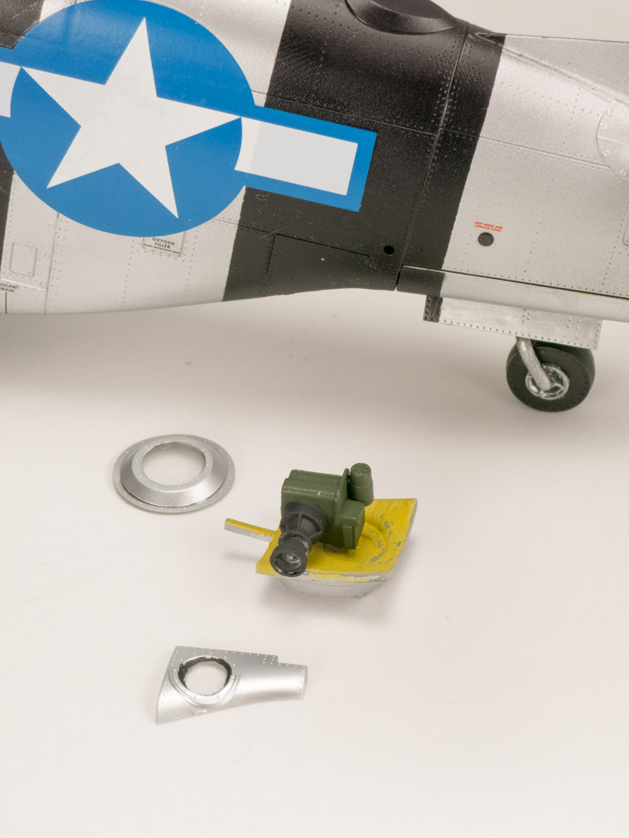
Camera and Ports
Camera Spine
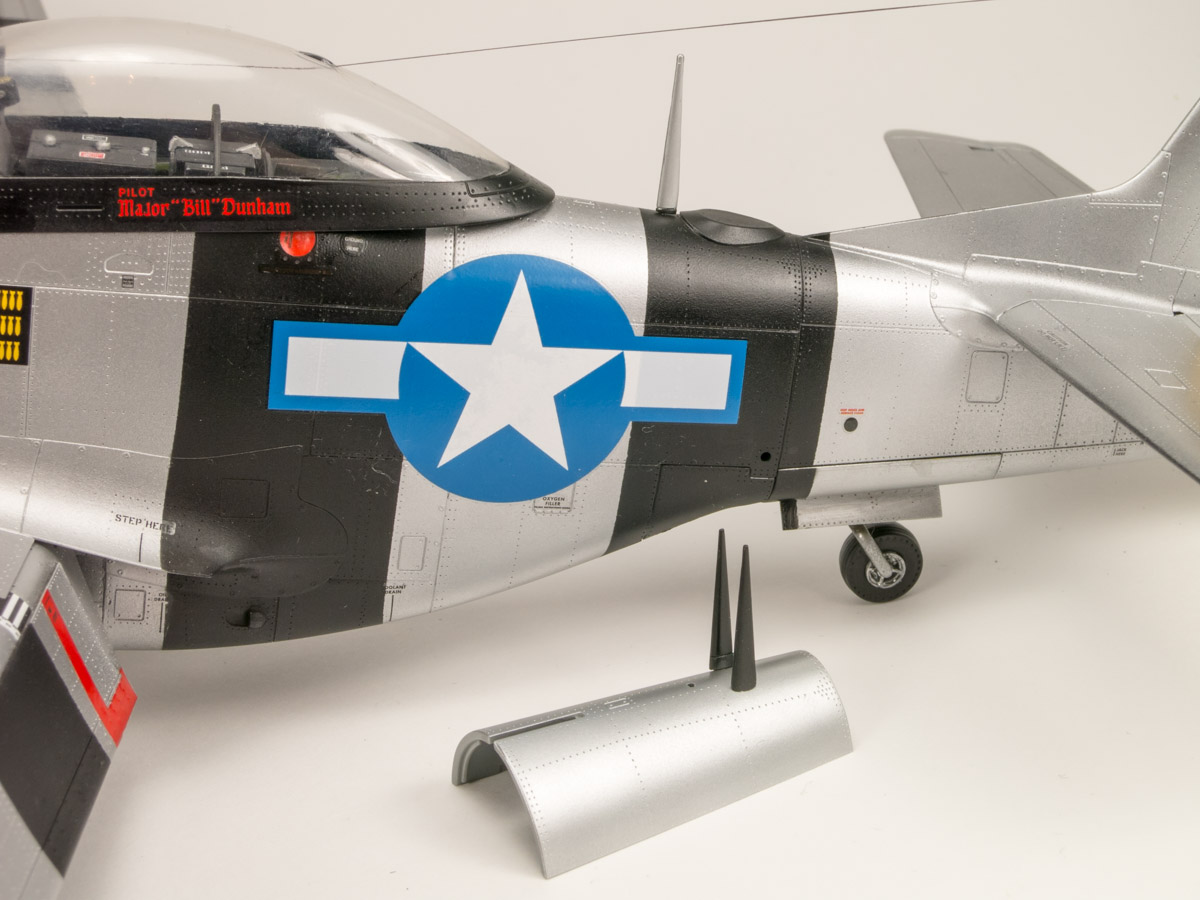
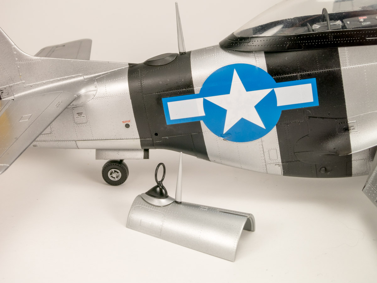
Uncle Dog Spine
Retracted Gear Parts
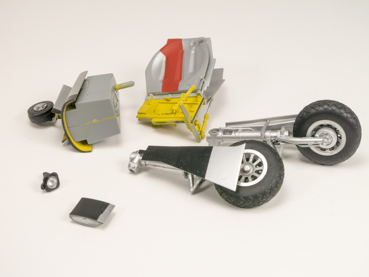
Deployed Gear Parts
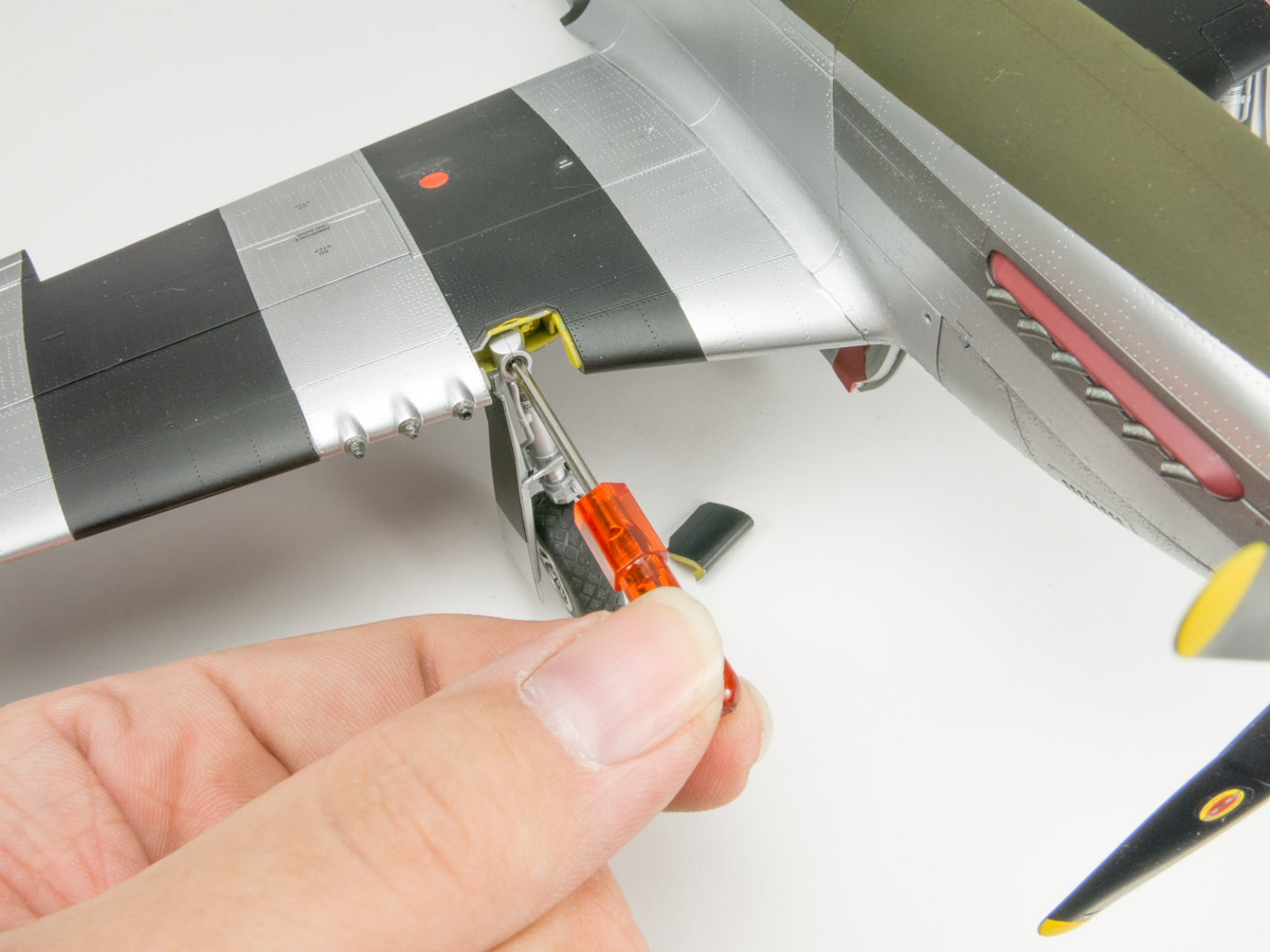
Removing Main Gear
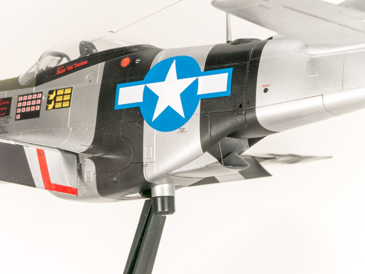
Attached to Stand
Comments
Building P51 - issues
Hi, Matthew.
Excellent review. I am building this model and it is very heplful (this is my second model, first Tamiya).
I also found some problems following the steps, as there are options that could lead to a mistake, for a rookie like me.
I am not sure if you could help me with 2 steps that I don't know how to proceed. And I am afraid to damage the parts (in special the cockpit).
Please let me know if you could help me; I will email my 2 question in another email.
Thanks a lot!
Add new comment
This site is protected by reCAPTCHA and the Google Privacy Policy and Terms of Service apply.
Similar Reviews