
Model T 1913 Speedster with American Sport Car Drivers
Introduction
Appearing on the market August 2020 is ICM’s rebox of their Model T 1913 Speedster introduced in 2018 with updated parts and the addition of a sprue containing two sports car drivers. Known for their detail, this Ukrainian based plastic model kit manufacturer has been producing highly detailed kits since 2003 with exports to several markets including North America.
History of the Model T “Speedster”
First introduced in 1908 at the Piquette Avenue plant in Detroit, Michigan and continuing until May 26, 1927. Ford produced over 15 million cars during this period. It had a 22 hp, four-cylinder engine, weighed in at 1200 pounds with a base price of $850. Touring, Runabout, and Town Car were the only versions of the Model T built in 1913. So, did Ford produce the Speedster? Henry Ford never officially produced the “Speedster” possibly because a Speedster did not fit his vision. However, he did offer in 1910 a bare chassis for sale. Also, during this period several independent companies offered bodies and parts to transform the Model T into a Speedster. Ford Speed & Power Equipment Company in New York was one of the companies who sold speed parts and bodies.
Box
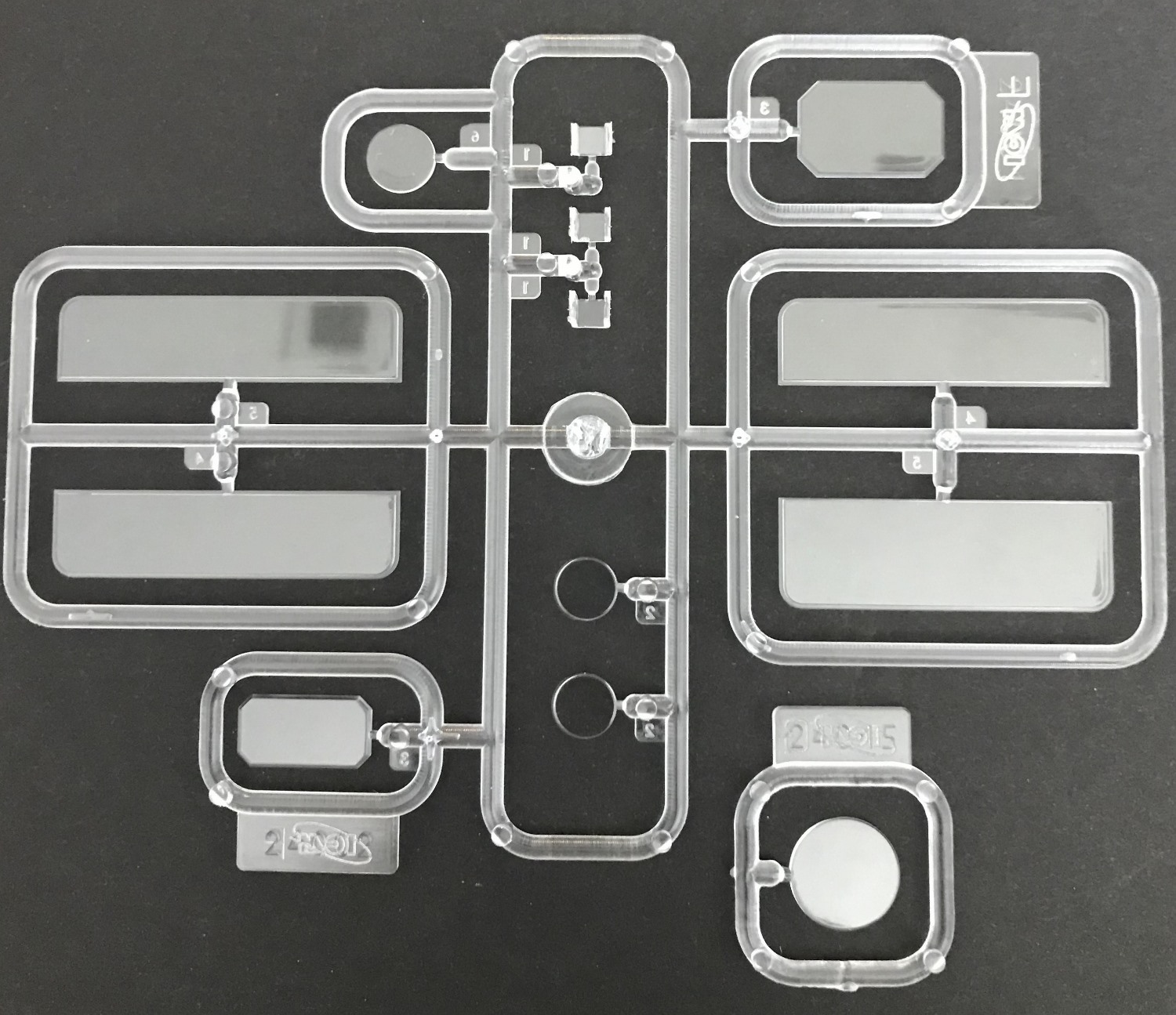
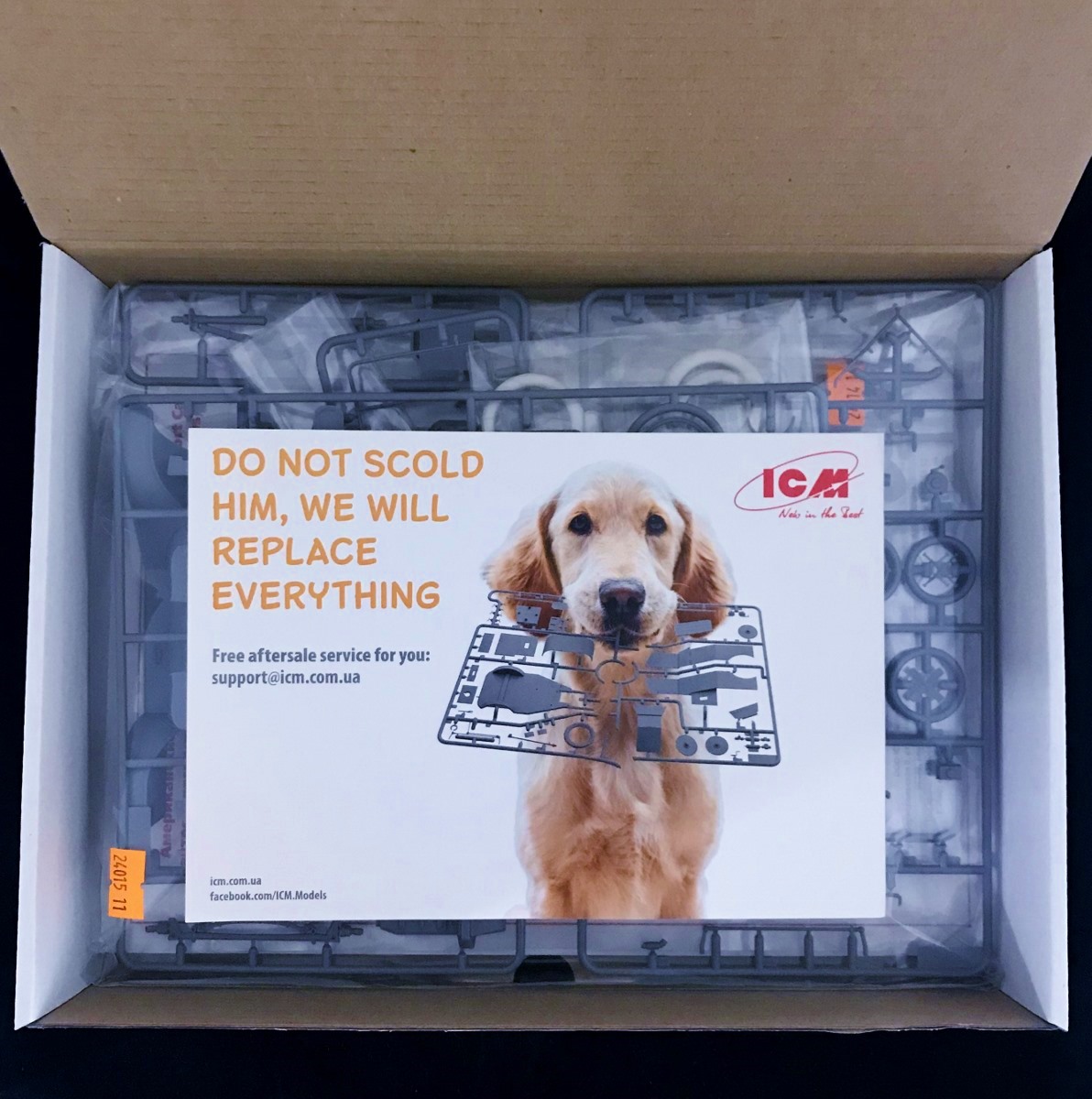
The outer box containing the box art and graphics is a normal size 12” long x 9” wide x 2.5” tall cardboard with an inner side opening hard cardboard box. It contains 6 grey sprues, 2 clear sprues all contained in protective polybags, one baggie containing the 6 tires in white rubber, a 12-page instruction sheet and 1-page figure painting guide. There are no decals included nor photoetch. Also, included is a small ½ sheet from ICM with contact information for free after sale service in the event a part is missing or damaged. A great perk by ICM.
Upon opening any model kit, what I like to look for is the amount of work, such as mold relief tapers, flashing, ejector pin release points (recessed or elevated marks), mold shift points, sprue attachment points and mold seams that need to be addressed during construction. The parts have crisp detail. The sprues have absolutely zero percent flash, except the vinyl tires which have quite a bit of flash. A few normal molding seam lines are present that need to be cleaned up. The attachment points are kept to a minimum and are in non-discreet areas. The Ford logos are molded crisp and should show up nicely with some dry brushing techniques.
- Three of the 6 sprues are from ICM’s earlier kit # 24001 “Model T 1913 Roadster” released in 2014.
- One sprue containing the floorboard and seats from ICM’s 2018 kit # 24015, “Model T 1913 Speedster.”
- The clear sprues are from ICM’s kits # 24015 and 24002 (“Model T 1911 Touring”).
- The one additional sprue included is the figure sprue which was initially released in 2019 as kit # 24014 containing two 1910 sport car drivers.
In summary, what you get for one purchase is two kits in one. Car kit #24015 and figure kit # 24014.
Instruction Manual, Paint/Markings Guide
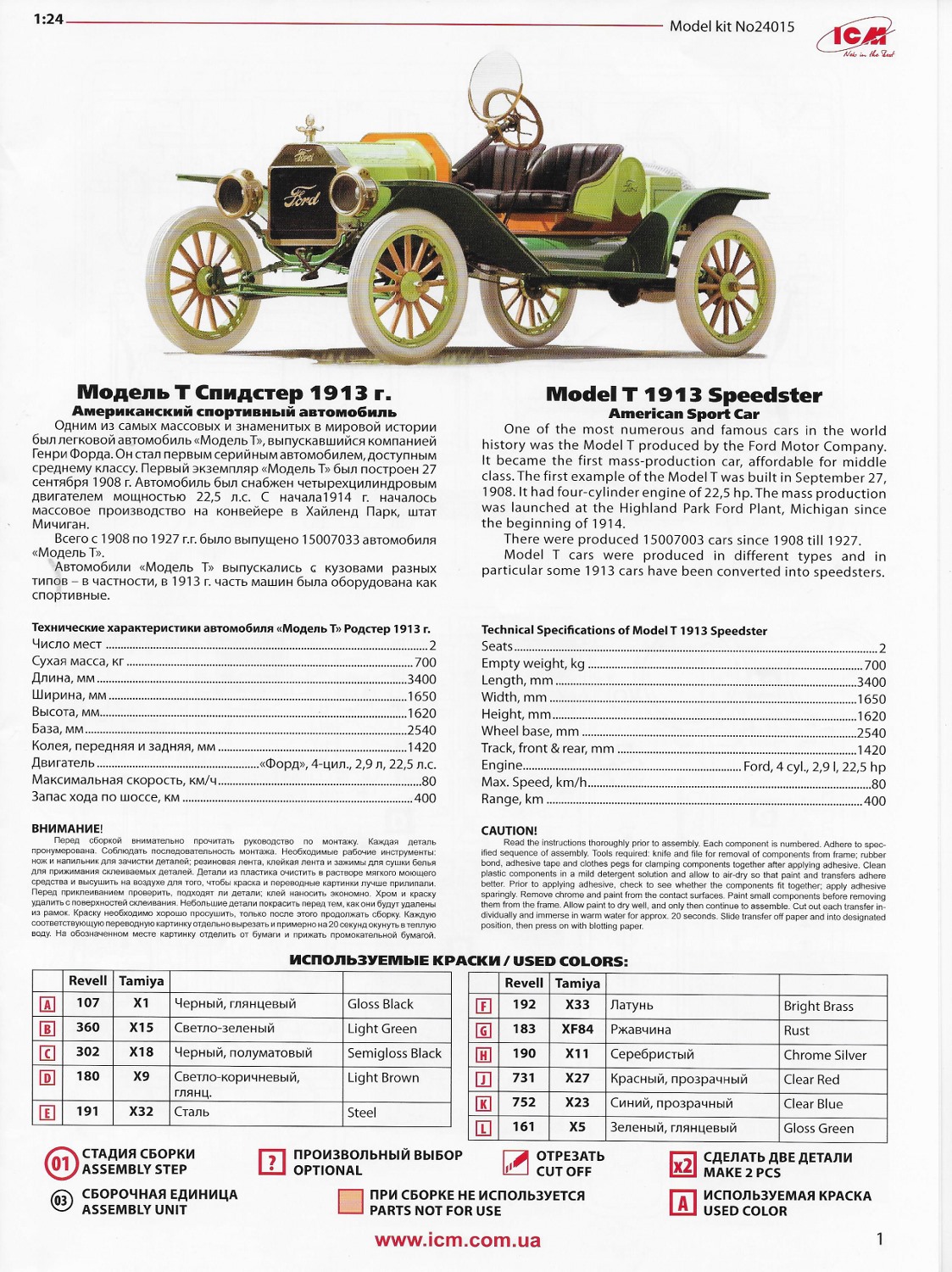
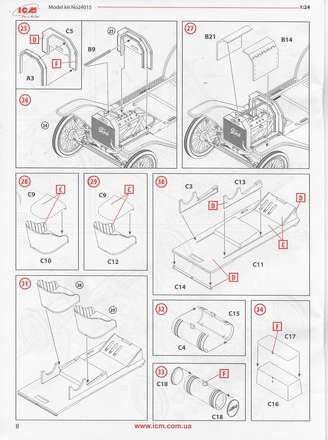
The instruction manual is printed in booklet style on glossy paper over 12 pages. The front cover page includes an image of the Speedster with a short history of the Model T along with technical specs and paint call outs for Revell and Tamiya paints. Part sprues are laid out on pages 2-3 with parts not used in the construction colored in pink. Building consist of 55 steps, which is deceptive as in most cases one step may comprise of only gluing one or two parts. Instructions are clear with attachment points indicated. Page 12 contains the paint scheme guide for one vehicle in two-tone green.
Let me preface my review by stating that as modelers we do not always follow the instructions step by step. We tend to skip around completing steps in advance while letting previous steps dry or bond. For this build and review, I did indeed skip steps, but I will describe what I found in each step, pros or cons, so the builder will be enlightened as to what needs addressed during the build.
The Build
Step 1-7
Assembling the 4-cylinder flathead engine comprises the first seven steps with 11 parts in the mix including the engine block halves, cylinder head, inlet manifold with carburetor attached, fan belt drive, oil filler pipe and cooling fan. Also, in step 6 is the attachment of the two engine supporting arms. Detail is quite nice with individual spark plugs molded into the cylinder head. Further detailing can be achieved by adding ignition wiring. According to the Speedsters website, http://www.speedsters.com/ford-speedster.htm, the original engine was stepped up in performance by adding a RAJO Overhead Valve Conversion with high compression heads, a hot cam, balanced crankshaft and a different carburetor. I’m assuming since sprues A & B are from ICM’s previous kit # 24001, 2013 Model T Roadster with the 4-cylinder flathead engine, any upgrades to the engine would not be present in this latest kit. The instructions do not depict the engine bonnet open. An open engine compartment could be accomplished by making a few modifications to the bonnet and hinges. Since the instructions call for the engine to be installed in step 12, I wanted to apply the paints and add some detailing before installing.
Steps 8-16
These steps consist of the assembling the two-part radiator, attaching the radiator to the separate front axle then to the body frame. The steering post is attached, headlight posts are attached to either side of the frame, and then the two-piece differential housing is attached to the rear axle. ICM has molded the differential housing with crisp bolts and detail. Step 12 calls for the installation of the engine and step 13 calls for attachment of the upper and lower radiator hoses. These steps will wait until the frame is complete and painted.
Steps 17-21
These steps consist of construction of the two-part exhaust with manifold attached. The exhaust tube was drilled out. Step 19 has the modeler install four manifold retaining stirrups. This also will wait until the engine is installed and the exhaust manifold is attached. In step 20 the front axle radius rod and steering arm are attached. Then in step 21 is the attachment of rear axle radium rods and steering gear rods. Noteworthy observation: The wheels and front axle could be made to articulate with a few modifications to the stub axles steering arms and track gear rods using metal pins.
Steps 22-24
Consist of preparing the vinyl tires and installing onto the wood spoked rims. The rims are molded with sprue gates on the rims so if one leaves the rim on the sprue painting will be much easier. Six tires are provided including one of these for the spare mounted on the rear. The tires do have some molding issues, namely some flash that must be removed. After trying to trim with an Exacto and sand the flash, I went with an earlier modeler’s discussion with another ICM kit containing vinyl tires, on using an open flame to soften the vinyl then roll on a hard surface. The white vinyl tires will be left unpainted since the color appears to be realistic to the period.
Steps 25-44
Consist of building up the interior including the two-part engine cowling with center support attached to the radiator frame, installing the seat cushions to the seat frames with supports, gluing together the fuel tank consisting of 4 parts, and the rear stowage box. The seat cushions do have crisp details. If the cowlings are to be shown open, then there are 4 sink holes underneath which will have to addressed. Additional parts to add include the high and low speed clutch foot petal, reverse petal, foot brake, emergency brake and clutch release hand lever. Next in step 38 the steering column is built up with the attachment of the spark and throttle levers followed by installation of the two-part steering wheel and finally the driver’s glass monocle frame. A mistake in step 39 lists the spark and throttle levers as parts B30, but in reality, they are parts B3 and B4. Parts B30 were used in step 37 when installing the foot pedals.
Steps 45-55
Complete the construction with the attachment of the rear spare, gull winged radiator cap, tail light, two headlights and the option to install the two coach lamps. The instructions call for circles in clear red and clear blue to be painted on the tail light lens. Unfortunately, there is no defined circle molded into the clear part, so the modeler will have to mask a circle or improvise by other means. I decided to punch a circle out of painters’ tape.
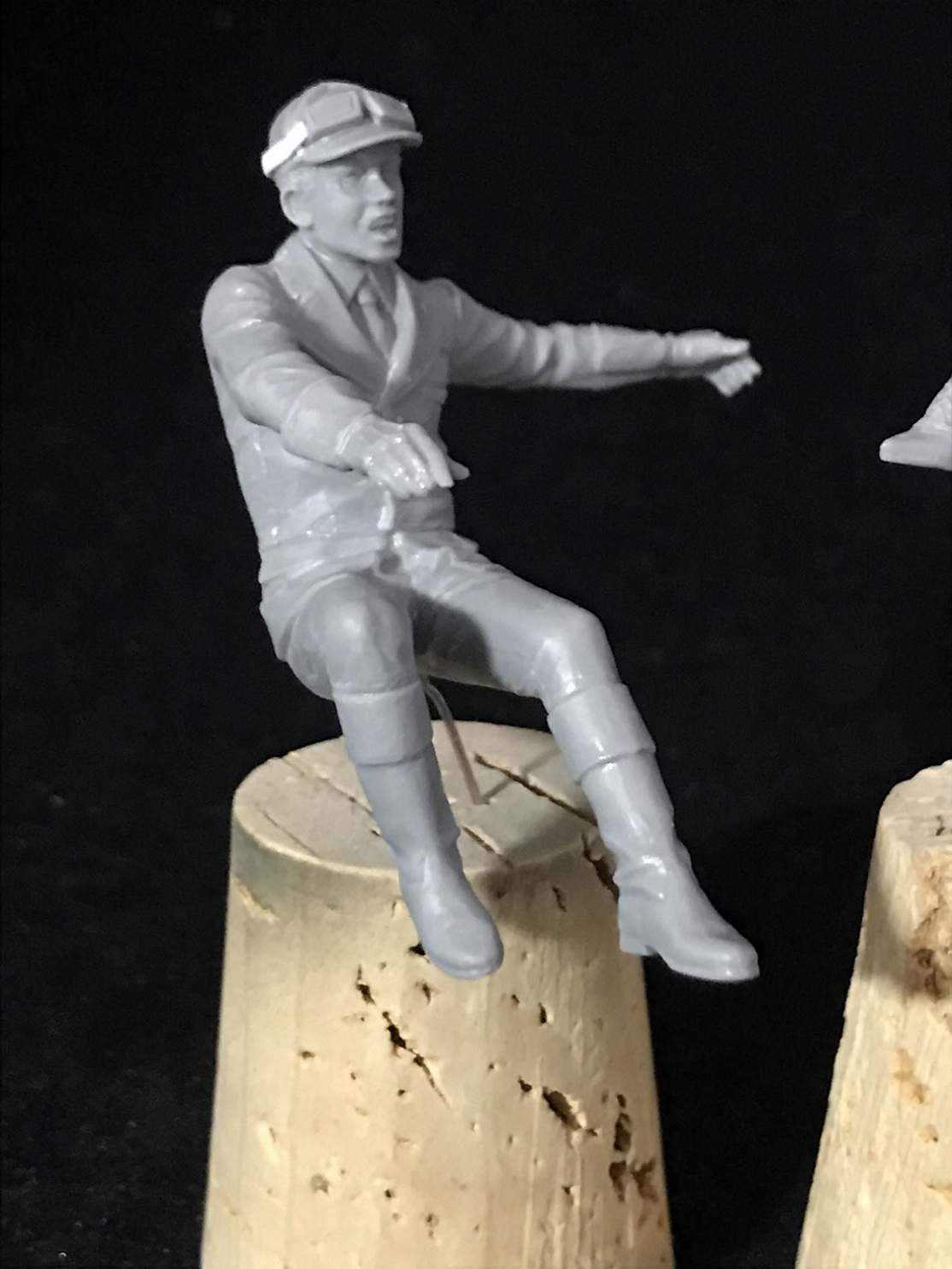
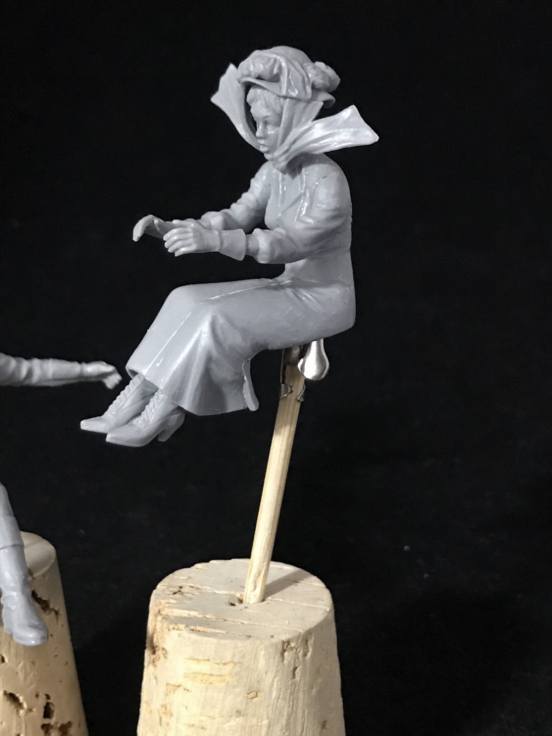
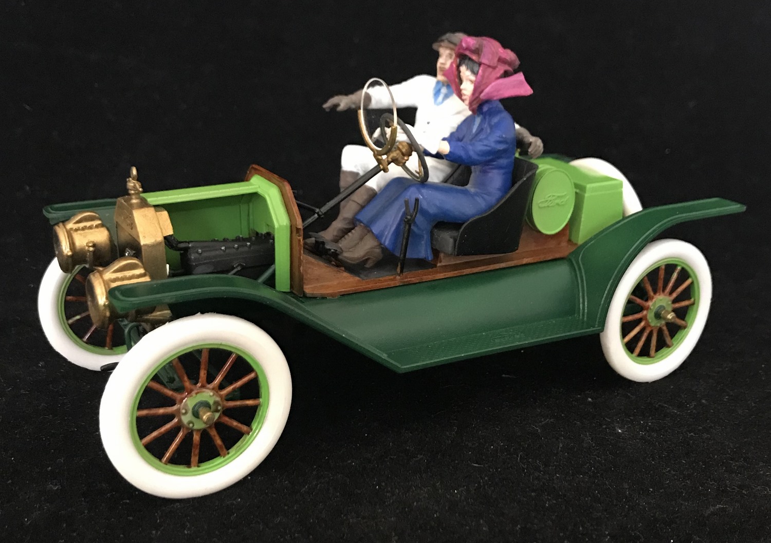
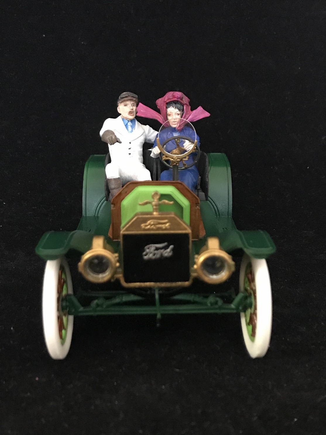
Two 1910 Sport Car Drivers
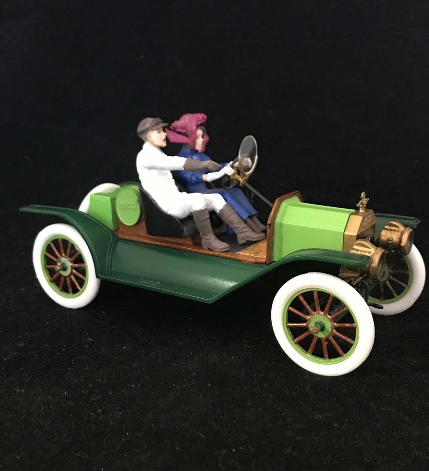
The final sprue contained the two sports car figures. One a male driver and the other a female all decked out in their fancy sporty driving ensemble. The male driver appears to be instructing the female driver in driving techniques by his finger pointing. The female driver is wearing a long dress and has a bonnet tied around her head. The male driver sports a dashing suit with trousers and goggles. However, the goggles have no strap attached. I added a strap using a strip of plastic card stock. Detail is excellent on both figures, as one can see by viewing before painting images, thus allowing the modeler a great starting point. As usual with two-piece figures, mold seams have to be cleaned up. Before gluing the arms and legs, final positioning was tested on the seats for proper fit. Although obvious from looking at the sprue, the male driver’s rear torso #7 is not listed on the call out profile.
Painting and Decals
ICM supplies only one paint scheme in the instructions which is a two-tone green. If the modeler researches images of the Speedster many color combinations can be found. In my research I did come across a website with a similar vehicle also painted in the same two-tone green. All parts were given a primer coat using A. Mig One Shot Grey Primer and A. Mig One Shot Black Primer. Engine was further painted with Tamiya Semi-gloss Black X-18. Engine detail was painted with various shades of paints by A. Mig and Vallejo. In order to replicate the two-tone green paint, I used the paints recommended in the painting guide (Tamiya Light Green Gloss X-15 and Gloss Green X-5).
Reference used for this review
- Victor Wilfred Pagé. The Model T Ford Car: Its Construction, Operation and Repair: A Complete Practical Treatise Explaining the Operating Principles of All Parts of the Ford Automobile, with Complete Instructions for Driving and Maintenance. Nabu Press, 2014.
Conclusion
I would have liked ICM to include sprue D molded in brass color as they did in an earlier kit # 24001. A mistake in the instructions in step 39 was found, but I’m sure this will be corrected. Other than these two observations, I found this kit to be very enjoyable to build. The quality of ICM kits is superb, easy to build, little clean-up involved, ICM’s attention to detail and top-notch instruction sheets all add to a gratifying build. The detail with the figures is remarkable having an enormous amount of detail with the exception of the goggle strap for the male driver. After completing each kit, I ask myself, “would I build this kit again?” In regard to this kit, my answer is “most certainly yes”.
Note: In researching a MSRP for this review, I contacted ICM and within 24 hours I received a response from the Managing Director of ICM Holding with an answer to my question. This is not the first time I’ve contacted the company for information. In each time a prompt response was sent. Great customer service.
Thanks to IPMS/USA and ICM Holding for allowing me to review this kit.


Reviewer Bio
Phillip Cavender

Phil Cavender, IPMS/USA #50085, is a retired pharmacist from the Veterans Administration, having retired in 2011. While he explored model car building as a child, it wasn’t until 2015 that he rediscovered plastic scale modeling. His renewed interest emerged while researching his father’s military history, which led him to a local hobby shop. There, he met a former UK military tanker who reignited his passion for the hobby. After relocating to Myrtle Beach, Phil teamed up with six skilled modelers to co-found the Grand Strand Scale Modelers chapter of IPMS/USA. He now focuses on building armor models in scales from 1/35th to 1/16th.
Comments
Add new comment
This site is protected by reCAPTCHA and the Google Privacy Policy and Terms of Service apply.
Similar Reviews