
Mercury Spacecraft
America's first manned space program was best summed up by Deputy Administrator, Hugh L. Dryden in the foreword to the book, Project Mercury: A Chronology (NASA SP-4001) where he wrote “ Project Mercury is now history In its short span of four years, eight months, and one week as the Nation's first manned space flight program, Mercury earned a unique place in the annals of science and technology. The culmination of decades of investigation and application of aerodynamics, rocket propulsion, celestial mechanics, aerospace medicine, and electronics, Project Mercury took man beyond the atmosphere into space orbit and confirmed the potential for man's mobility in his universe. It remains for Projects Gemini and Apollo to demonstrate that potential.” There are many fine books on Project Mercury, you can use your computer's search function to find them or go to your local library.
Horizon Models is a new company in the Real Space modeling world, based in Australia where this model was designed. The parts were molded in China, shipped to Australia and packed into boxes that were made and printed in Australia along with the photo-etch. The decals were made in America by Microscale and both the decals and the photo-etch sheets are packed in individual bags . The kit comes with two sprues, each one alike, that allows one to build two Mercury spacecrafts and two boilerplate capsules. The decals will only allow you to make two Mercury and one boilerplate capsule. The parts were injected in a medium gray plastic with no flash. Some of the parts are very fine and I found that it was best to remove those parts (such as the escape tower parts) from the sprue using a razor saw. The kit provides parts to make two stands for your models. Finally, the instructions can be found on the bottom of the box. If you go to Horizon Models website you can download and print out these instructions on paper for your convenience.
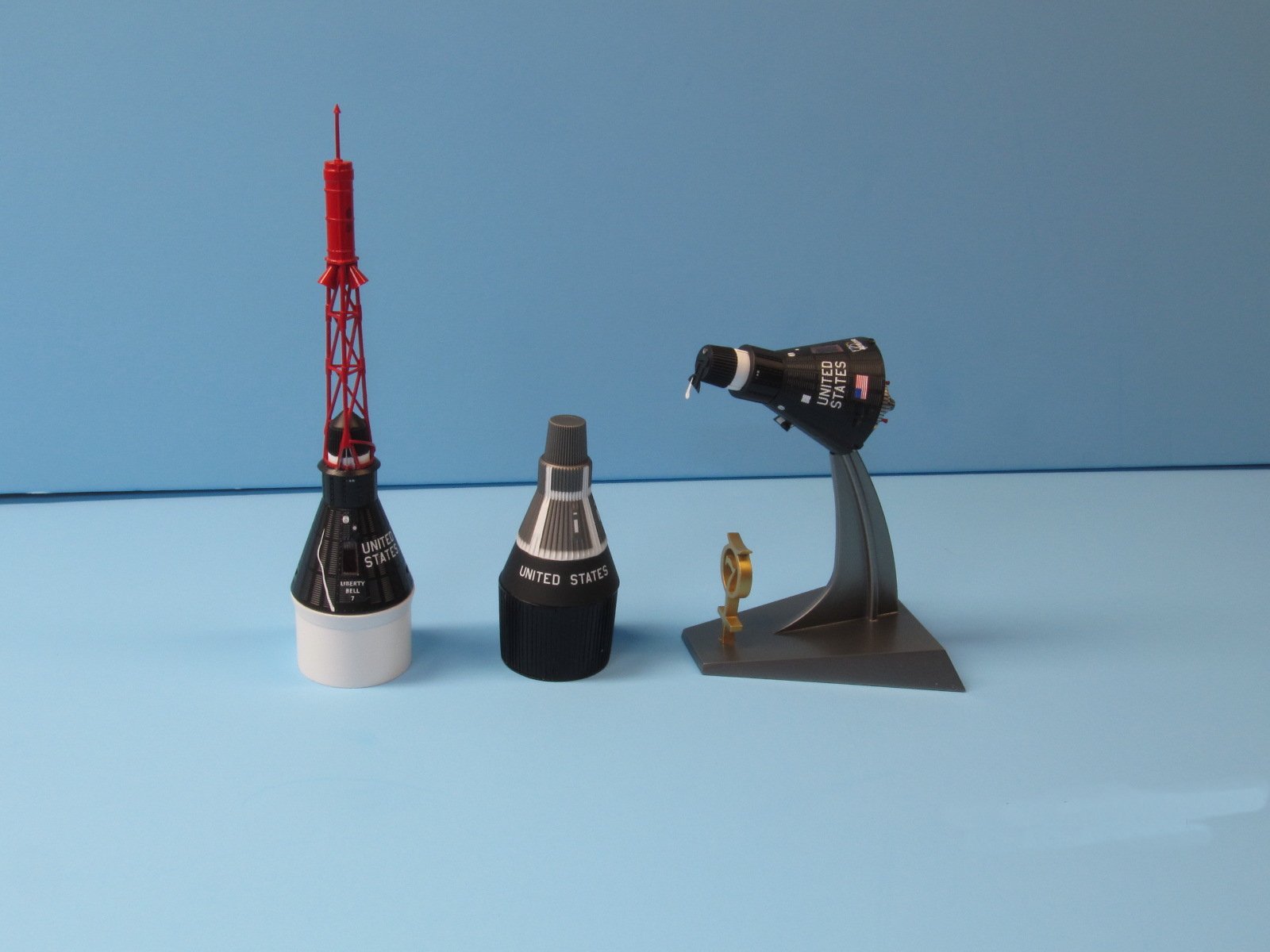
Looking over the options I decided to build the “Big Joe” boilerplate capsule launched on an Atlas rocket in 1959, the MR-4 Mercury capsule of Gus Grissom on top of the Redstone rocket in 1961, and the MA-7 Mercury capsule of Scott Carpenter as it would appear in orbit in 1962. I started with the boilerplate capsule, which only required removing it from the sprue and painting it. The kit only provided two heat shields so I did not use one on the boilerplate capsule. For display purposes I decided to make the Atlas adapter. I had some left over one inch PVC tubing, which runs about 1.050 inch diameter and was perfect as the maximum diameter of the Mercury capsule is 74.5 inches and in 1/72 scale that comes out to just 1.035 inches. I cut a three inch piece of PVC tubing and placed it in my lathe and turned the slight taper that was required. ( all dimensions for the adapter came from Peter Alway's book, Rockets of the World, 4th edition, page 245) After that I used some .010”x.010” square stock to create the ribbing on the adapter. I then painted it gloss black and my display stand was done. The boilerplate capsule required several sessions of taping and painting till all the white, titanium, and black was applied. The model was finished with the #11 decal ( United States) and a few white decals (#12 x 4).
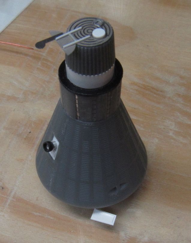
The MR-4 capsule began by gluing together the central hub parts (M15x2). One then needs to attach two pieces of photo-etch (PE1x2) the only problem is this would be proud of the surface where the other molded in detail was just at the surface. So I cut a small channel along the glue joints so the PE1 would fit into the channel just at or below the surface. There is one other problem with this part. At the top is the base for the antenna canister and when you put part M18 on top of M15 you will notice that M18 is wider than the M15 section it mates to. You can't reduce M18 as it is ribbed, so I solved this by making a strip the width of the band out of .005 inch sheet plastic and attached it to the top of M15 wrapping it around. This was enough to make a closer fit. It would have been simpler if they had designed M18 ( the antenna canister) as one piece, but I'm not a programmer so maybe I'm missing something here.
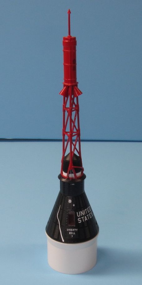
MR-4 was the second sub-orbital Mercury flight and Grissom's capsule had several changes from the previous mission. Instead of two “portholes” it would have one large window that all future Mercury capsules would have. The model represents this with raised details, which on the face of it would have been alright but for the fact that it is too narrow and doesn't look quite right. I solved this by making a new larger window that had two panes like the original. I used a 1/32 inch drill and drilled holes until I could remove the old window. I then used a #11 exacto blade to widen the slot. The kit's window has two rows of rivets on either side, I just carved out the first row on each side to make the window wide enough. I then used some .010”x.030”plastic strip and glued that along the sides to create a step and some depth for the window. I painted the inside with a dark red color to represent the RTV sealant used on the real thing. The flange or step was painted in a steel color enamel. When dried I cut a piece of clear .015 inch plastic and flipped part M1 over and used white glue to attach the clear window to the bottom of the plastic frame I had made. The second pane, the outer panel, would be made and attached only after the final painting had been done.
The next step was to glue the heat shield (M9) to the central hub (M15) and let it dry. To form the bell shape capsule you have to glue parts (M1, M2 and M3) together so the wide base goes against the heat shield and the narrow side goes under the cylinder on part M15. I glued in M1 first and then worked counterclockwise (well it was made in Australia) gluing M3 and then M2. I would let M1 dry for a while so it would not move around while you're trying to fit the next piece, M3 and so forth. Go slow and the better you get the fit the less glue you'll need and the smoother the joint will be. After all the three parts are glued in I would let it dry overnight. The kit has roll jets on parts M2 and M3 just above the base. The kit's jets are too shallow, so I used a small cylinder bit on my dremel tool to deepen these four slots. Making them deeper at the widest part and tapering to the surface at the narrowest part.
Next up is the escape (or launch) tower assembly. The escape rocket is formed by gluing parts M8 and M12 together. Photos of the real escape rocket shows three flat straps that circle the motor The kit represents this with a thin bead that I scrapped off and cut thin strips out of a lead sheet to form the straps. These were glued on using CA. The tower is made by gluing the three sides (M7x3) to each other and then gluing the legs into the base (M17). One has to be careful here and take time keeping the alignment among the three sides the same. At the base of the tower each leg forms an inverted “V”. At the narrow top on two of the legs there is a wedge where wires from the escape rocket pass down the hollow legs and come out at the wide bottom of the wedges to continue into the capsule. I made these wedges from a strip of .040” plastic and glued them in place. The kit would have you use photo-etch to make the wiring, but I'm not a fan of photo-etch in this instance. I used .010” and .015” lead wire to form the wiring as per photos. The two curved pieces that connect the legs near the base was made from .020”plastic rod that I bent and glued to the legs. After I primed the tower and I looked at photos of this area I decided that I needed to make the lip that is at the base and connects to each leg. I used some .010”x.040” plastic strip that I bent into a curve and cut to length to fit between the legs. Once this was done I glued the escape rocket to the escape tower.
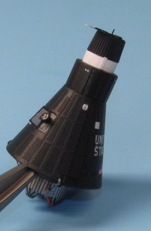
I wanted to display the MR-4 capsule in the upright and vertical position, so I used the remaining piece of PVC pipe and turned the upper part of the Redstone rocket on my lathe. Once again I used Alway's book for reference on the dimensions. After this was done I cut a piece of paper as a mask to protect the window's painted interior. This was glued on using some white glue so it would be removed later. I primed the capsule with Tamiya grey primer and after drying corrected any flaws that I found. The Mercury capsule has been described as being very dark, almost black in color with a hint of blue. To get close to this I used Mr. Color #2, gloss black and Mr. Color #14, semi-gloss Navy Blue, mixed 4 parts black to one part Navy Blue. The Navy Blue lightens the black somewhat and added a hint of blue. Standing by itself the capsule looks black, but if you place something that is black next to it you notice that it's a shade lighter. Using Mr. Color paints resulted in a very smooth surface so I didn't need to add a gloss coat for the decaling. I attached the pitch and yaw jet decals (#5x4) first and then the C and S band antenna decals (#4x3). I then attached the mission logo decal (Liberty Bell 7) and the bell crack decal. The “United States” decal (#1x2) was then placed on the capsule, but I did not use the instruction sheet as a guide for this, as they got the location for MR-4 wrong. Horizon Models instruction would have you place these decals in the same position as the orbital Mercury missions, when they need to be in the same position as placed on MR-3 mission. There is a big difference in location, and the flag decal under the “United States” is not used either for MR-4. I allowed all the decals to dry overnight then sprayed on a semi-gloss clear coat over the capsule to seal them in. After this coat had dried I attached the escape tower to the model and glued in on. The last thing was to remove the paper mask from the window and cut some .015” clear plastic into the window shape. I used some Future to glue the window in place and the MR-4 capsule was finished.
The MA-7 capsule of Scott Carpenter followed the same methods used above on the MR-4 capsule. On this model I wanted the periscope deployed, it is located on part M3 with raised lines (like the window). Again I drilled out the opening and used a #11 exacto blade to widen the hole. I used some .010”x.030” plastic strip to frame the inside of the window and then added a piece of .015” plastic to fit on the backside to form a floor. I then drilled a 1/16” hole and glued in a piece of 1/16” Aluminum tube to represent the periscope. I formed the door by bending a piece of .005” plastic after I had cut it to shape.
This capsule will be displayed in the orbital mode and as such the antenna canister requires some added details. Horizon Models uses photo-etch part PE6 for this detail and it is very nice indeed, but more detail can be added and I did. I used some .010”x.010” square plastic stock to make the hinges for the de-stablizer flap and a piece of .020” rod stock to represent the spring. I punched out a plastic disc and used that as the drone chute cap. Some 1/16” Aluminum tube was used to make the two horizon scanners. The top one was cut very thin and glued to the top of the canister, while the side one was thicker and was inserted into a 1/16” hole drilled into the side of the canister. Finally, some very thin stretched sprue was glued to the center as the center post.
The final area where the MA-7 capsule differed from the MR-4 capsule was it included a retro pack, which consists of two parts. (M21 and PE3) The plastic part (M21) is the complete retro pack, on it you will notice three small cylinders among the retro rocket covers. These are the posigrade rockets that gives a slight push to the Mercury capsule at the moment of separation from the Altas rocket to widen the distance between them. Well, these small solid cylinders should be small rocket nozzles. So using a piece of .040” plastic rod, a small file and some sanding sticks I made the three small nozzles. I cut the small cylinders off of the retro pack and drilled a small hole at each location for later reference. Then I primed and painted the retro pack with Alclad II Aluminum. On the orbital flights the retro packs had black lines painted on so it would stabilize the heat/cold. Horizon Models duplicates this with three decals (#2x3, #3x3 and #10). This is where some problems topped up. Decal #3 goes on top of the retro rocket covers, the problem is the very thin lines on the decal. After soaking the decal in water, it's like trying to pick up a wet spider and put it on top of the retro cover. The solid center fits well, but all the little line want to fold onto themselves and even taking a long time to try to untangle them I was never very successful. The other problem with this decal is that the lines are too short, yes too short. The decal as made will not cover the whole retro rocket cover, but then again if they were longer I don't know if it would be easier to position them or make it even worst. I let dry the decal and then placed the other decals on the retro pack without further problems.
If you look at pictures of the retro pack you will notice that the black lines on the retro rocket covers are tapered, thicker at the base and tapering to a narrow line at the top. So to save the situation I decided to try to paint these lines on using a 10/0 liner brush that I had. I used some thin black enamel paint and while I finished the lines I'm not really happy about it. The photo-etch member in this equation represents the straps that hold the retro pack to the capsule's heat shield. I glued the straps on the retro pack after slightly bending the legs to fit on the pack. Then the straps at the edge of the pack have to be bent further down so the straps will touch the heat shield edge. Along the capsule's base there are three locations that don't have some shingles, this is the locations where the three straps go. At the end of the photo-etch straps are two pieces, the one that is a straight line from the pack to the capsule is the strap, the other represents an electrical line. I cut off these PE electrical lines and used some .010” lead wire to replace them and ran them all the way to the pack.
The MA-7 capsule was primed and painted in the same manner as was the MR-4 capsule. The decals were applied using the placement as indicated in the instruction sheet. The model was sprayed with an egg shell clear coat to seal the decals in and give the model a slightly flatter look then the MR-4 capsule. Plastic parts M10, M11 and M14 were glued together to create the display stand. I modified the seat so the capsule would be in a lower stance, after all it was in orbit. The base was sprayed with Alclad II Magnesium and the Mercury emblem was sprayed with Mr. Color Brass. The model was glued to the base and it was completed.
I want to make one more comment before I wrap this up and it concerns the photo-etch. Horizon Models has tried very hard to enable you to build any Mercury mission ( manned or unmanned). While the assembled capsules are the wide window type, by using various photo-etch parts you can replicate the “port hole” window capsules that were used early on in the program. They even provide the smooth entrance hatch used on these early missions as well. Mission logos for all the manned flights from MR-3 to MA-9 are on the decal sheet. The decals are very nice and conform to the shingles very well using the Microscale Set and Solvaset system.
You might think that with all the extra things I did I wouldn't think well of this kit, but that's far from the truth. Straight out of the box someone could put together a very fine model of the Mercury spacecraft. I would definitely give it a 9 out of 10 and I think for the first kit by a new model company that they did very well indeed. I have no problem in highly recommending this kit to any modeler and I look forward to anything that Horizon Models comes out in the future.
SPOILER ALERT: Looks like I will not have to wait long, as in the first quarter of 2016 Horizon Models is coming out with a 1/72 scale Mercury/Atlas launch vehicle (#2002). I'm excited about this and can't wait to get one.
The changes to the model that I made I did because I wanted to make the model better. To do this one must have good photos and excellent references One can use the computer's search functions to find a wealth of material on the Mercury program. In my humble opinion I think that the best reference anyone could get would be the Space in Miniature #5; Mercury: A Guide for Scale Model Builders by IPMS member Michael J. Mackowski at http://spaceinminiature.com (photo copies only available presently for #5).
I want to thank Horizon Models and IPMS/USA for allowing me to do this review.


Big Joe 9-09-59 Note Location of White Marks not at base of cylinder
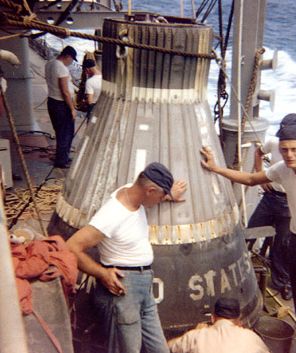
Big Joe Recovered -Note Side with United States has White Stripe
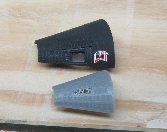
Porcess to enlarge window beside 1/48 Revell kit

Window cutout complete, Revell 48th scale underneath
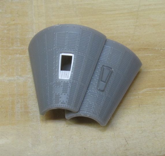
New window compared to kits part

Atlas Mercury Adapter tuend on lathe

Drone chute lid added hinge mechanism added and two horizon scanners
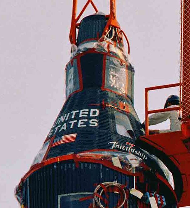
MA-6 Glenn pre launch note good pic of wedge on tower foot inline with window and clamp underneath Friendship 7
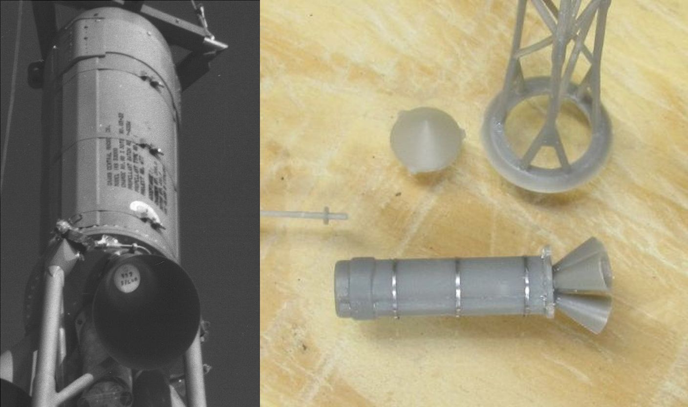
Escape motor straps added with lead strips
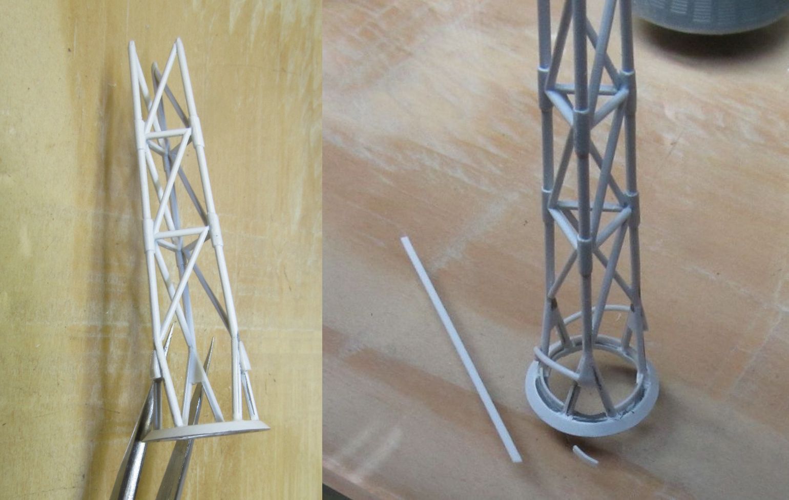
Escape tower - plastic wedges added, curved lip added to base, curved rod added to 2 legs
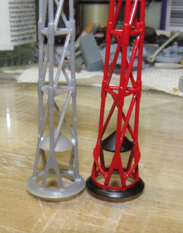
Unmodified,unpainted tower left - Modified, painted tower right
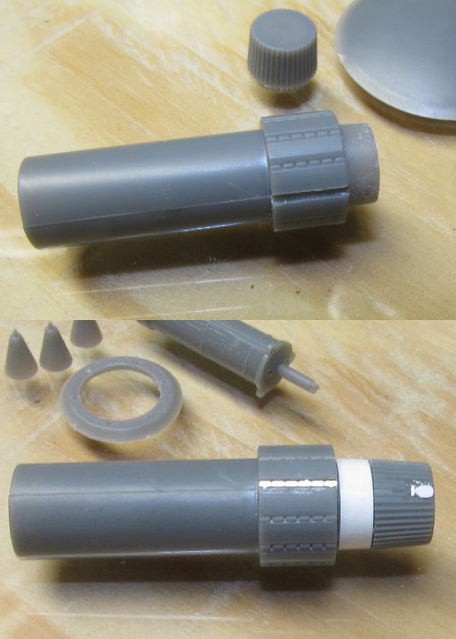
Part M15 - top channel made, bottom PE added

Posigrade nozzles made-retro pack finished
Opening for periscope made and periscope insered
MA-7 showing periscope side

Mercury boilerplate capsule masked & painted
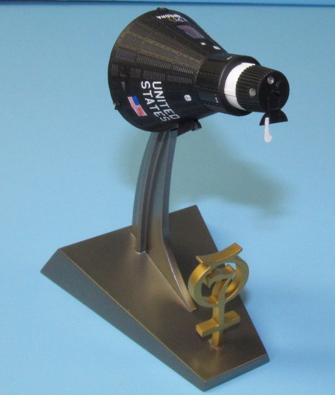
MA-7 capsule on stand
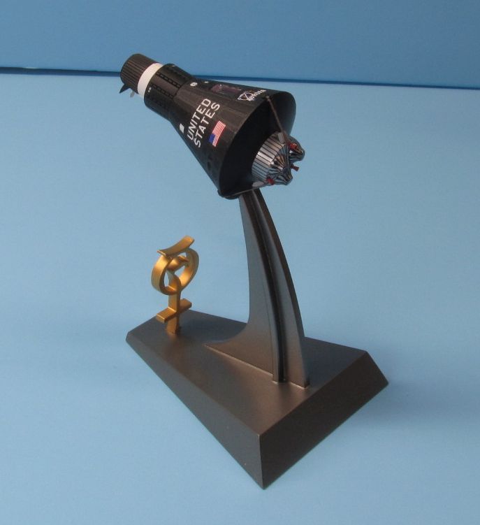
MA-7 Carpenters Mercury capsule in orbit mode
MR-4 Grissoms Mercury capsule
Comments
Add new comment
This site is protected by reCAPTCHA and the Google Privacy Policy and Terms of Service apply.
Similar Reviews