
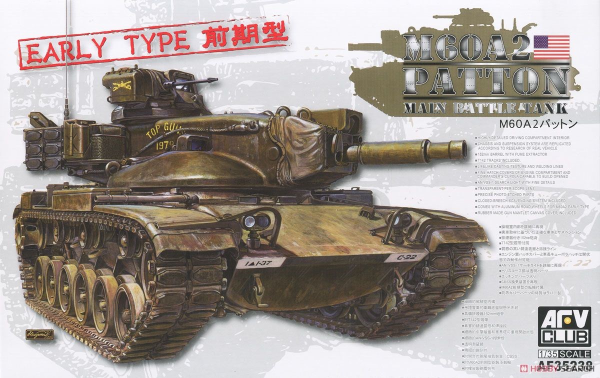
M60A2 Patton Early Type
Introduction
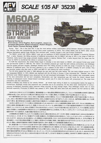
Without giving a lengthy history of the M60 Patton the following is a short summary of the M60A2. The M60A2 nicknamed the “Starship” grew out of the development of the M60A1 with a CVWS (Combat Vehicle Weapons System) turret firing a 152mm conventional round. Planning began in the late 1950s. These were initially named the M60A1E2 then later standardized to the designation M60A2. Production was ended in 1975 with a total production run of 526 vehicles.
In the advertising literature AFV Club states this new kit features:
- Highly detailed driving compartment interior.
- Chassis and suspension system are replicated according to research of real vehicle.
- 152mm barrel with fume extractor.
- T142 Tracks included.
- Lifelike casting texture and welding lines.
- Fine hatch covers of the engine compartment and commander’s cupola capable to build opened.
- AN/VSS-1 Searchlight with fine details.
- Transparent periscope lens.
- Precise photo-etched parts.
- Closed-Breech Scavenging System (CBSS) included.
- Comes with aluminum road wheels for M60A2 early type.
- Rubber made gun mantlet canvas cover included.
Box
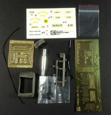
The box is a normal size 15” long x 9.5” wide x 2-2/4” tall containing 12 cellophane bagged olive drab green sprues, one cellophane baggie containing the turret assembly, one baggie containing the 50 cal MG, one small baggie containing the deck parts, one small baggie containing the rubber gun shield covers, one bag containing extra T142 track links in black, two baggies containing the clear parts, one bag containing the lower hull tub with vinyl tracks runs, 2 metal pins for track connections, one metal 152mm metal barrel with rifling, and one small baggie containing a small decal sheet with two photo-etch frets and a length of string. Additionally, AFV Club has included a one-page Boxart image of the M60A2 Patton Early Type suitable for framing. A nice touch as always. Also included is a 20-page instruction sheet with over 39 steps and the painting and marking guide in color for 2 vehicles on page 20.
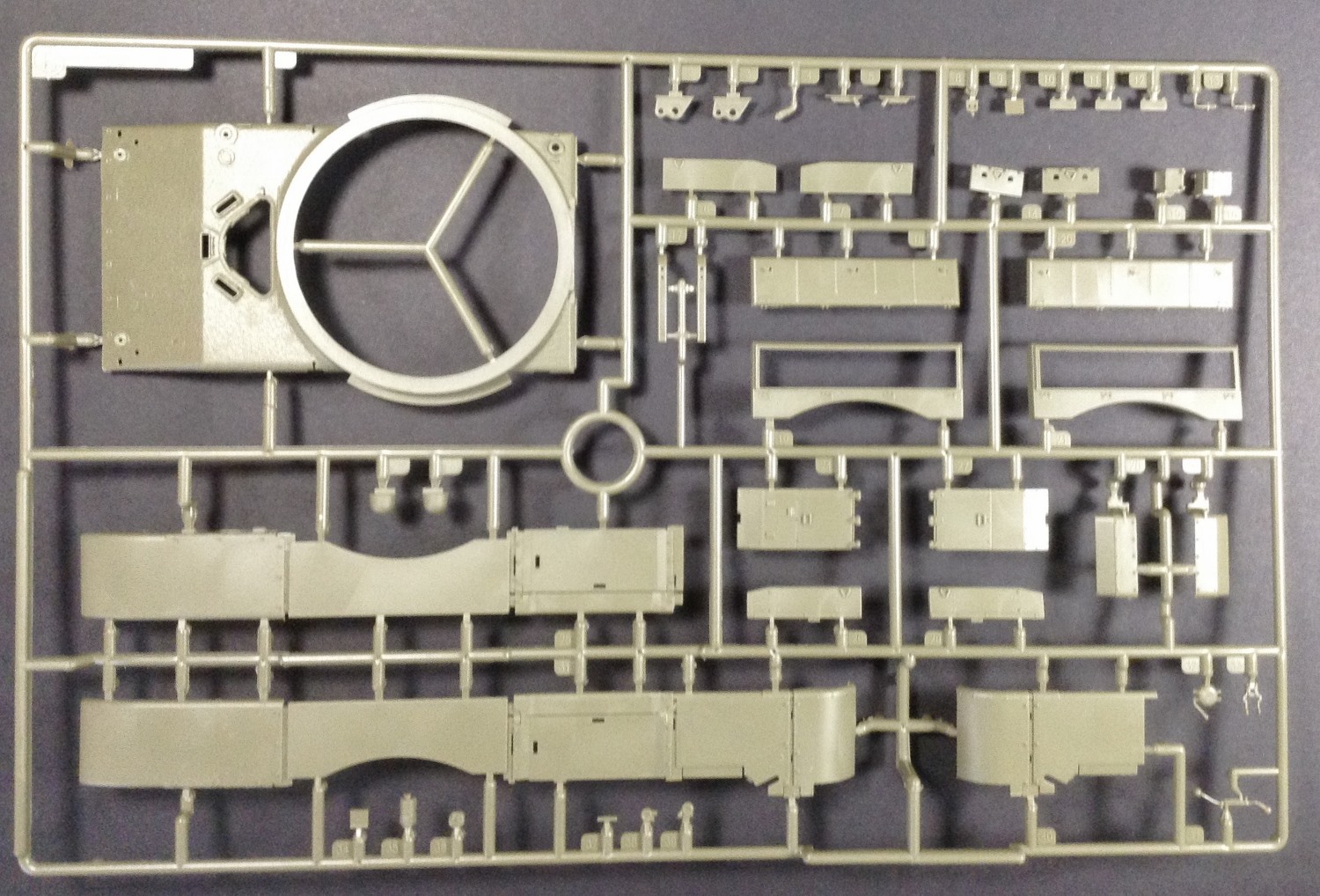
Sprues
There are a plethora of sprues with most coming from past kits such as AFV Club’s M60A1 kit # 35060 released in 2015 and AFV Club’s M60A2 kit # 35230 released in 2016.
Upon opening any model kit, what I like to look for is the amount of work, such as mold relief tapers, flashing, ejector pin release points (recessed or elevated marks), mold shift points, sprue attachment points and mold seams that need to be addressed during construction. The parts have crisp detail with little flash located on a few small parts. A few pin release points were seen which will have to be sanded or filled.
Instruction Manual, Paint/Markings Guide, Decal Sheet
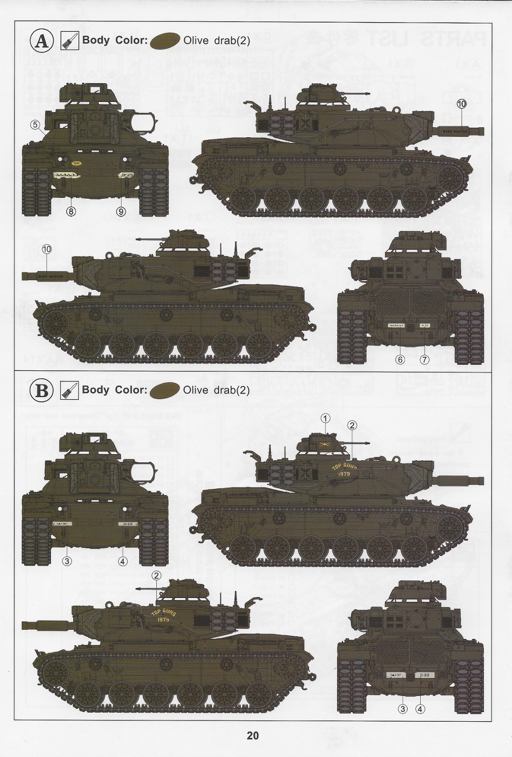
The instruction manual is printed in color measuring approximately 8-1/4” x 11-1/4” in a portrait orientation. It contains thirty-nine steps on eighteen pages, one page of parts layout and the last page contains the paintings and markings guide for two vehicles of clear sometimes cluttered diagrams in typical AFV fashion. Page 2 contains the color list for GSI Creos, Humbrol, Revell and Lifecolor. There is plenty of room for notations prior to or during the building stage on the sheet. The paint and markings guide allow for decals of two vehicles both in olive drab. One for the “Bush Master” and “Top Gun 1979”
Even though there are quite a few aftermarket items which could be purchased and used, this kit straight out of the box looks to be a fine representation. With that said, I look forward to building this early version of the M60A2 Patton. Additionally, as modelers we do not always follow the instructions step by step, however in this review I will describe any irregularities or problems I encountered in the build step by step. Now for the fun process.
The Build
Steps 1 through 21 consist of building the lower and upper hull. Read the instructions for these steps as each step depends upon the next. Test fitting ensures correct alignment and placement as the instructions sometimes not apparent.
- Steps 1, 2, and 3 consist of constructing the suspension, adding the torsion bars and adding the lower escape hatch with grab handles. As with all small molded grab handles cleanup is difficult, so bent wire would be a good replacement. Whether the grab handles will be seen with the upper hatches open, I will see later in the steps. No real issues were noted or seen with construction. Very little cleanup was needed. The parts fit on the lower tub well. The lower tub has cast texture molded in what appears to be well cast as seen from reference material. Additional weld beads were added to the brackets holding the suspension arms. Pay close attention to the suspension arms with torsion bars attached. They are denoted as D4 and D4-1. These attach at different locations. Upon first inspection I assumed the suspension would be workable, but upon construction I found the torsion bars inserted into keys inside the tub. Thus, an articulating suspension is not possible without major modifications. However, there is some “play” which allows leveling and lineup of the axles.
- Step 4, 5, and 6 consist of constructing the rear lower hull with attachment of the fairing (part O1) to contain the CBSS which were used on in-service Early M60A2 versions. The test vehicles M60A1E1, according to references did not have the CBSS (Closed Breech Scavenging System) with the rear hull bulge in use only the in-service versions. They had hulls like the M60’s and M60A1. Road wheels, sprockets and return rollers are also constructed in this step. AFV Club has molded casting numbers and foundry stamps into the hull. Also, in these steps are the construction of the fourteen two-part road wheels with a rubber O-ring (part # RA), two sprockets and six rollers. The O-ring allows for easy pressing on and removal for painting. The six-spoke aluminum road wheels are provided as well as the later steels wheels. The steel wheels can be added to your “stash” of parts. AFV Club has molded clean out holes into the sprockets which does save a lot of time from having to drill these out. A nice touch. Step 6 instructs to attach the road wheels. The road wheels will be installed at a later step after painting.
- Steps 7, 8, and 9 consist of building the interior drivers compartment. There are several small parts and a small piece of PE for the shifter mechanism. At this point the interior and detail need to be painted. Since I was leaving the hatch closed, I constructed the interior, but did not paint. If one decides to leave the hatch open, a partial view of the interior can be seen. Also, one must drill out several small holes on the underside of the upper deck. AFV does not indicate drill size, however a rough size can be obtained by measuring the headlight guards in step 21.
- Steps 10 and 11 consist of adding the engine deck louvre doors with corresponding grab handles. The engine deck alone requires the installation of ten individual doors with corresponding grab handles. Other than the small handles, I saw no issues. Molding detail is very good with respect to the louvers and the handles.
- Steps 12 and 13 Step 12 is the installation of the tracks. These were left off till later in the build. The tracks, as with most vinyl and rubber band tracks, have a seam line running the entire outer end connectors. Weathering should hide this seam. At Step 13 is the installation of the fenders. There are several molded-on tool attachment points which were removed on the front sections. Ironically one side is molded as one section while the other side is molded in two pieces. One of my kit fenders was warped. But with a little tender care I was able to persuade it into the correct position.
- Steps 14, 15, 16, 17, and 18 consist of constructing the fender boxes and attaching to the fenders. In step 16 AFV has failed to denote the two air cleaner boxes as subsections. These are added to the fenders in the step 17.
- Step 19, 20, and 21 consist of the modelers choice of adding the deep-water fording exhaust stack or using the supplied replacement door in the right-side grill door. I chose to not use the stack. Additional parts are added such as light guards and mud flaps.
- Steps 22 through 36 cover the construction of the turret assembly with the M84 machine gun with a vinyl covering, metal gun breech, hatches extra track lengths, smoke grenade launchers and tubular side baskets. The commander’s cupola has a clear insert for the clear parts which necessitates masking before painting. The turret hatches have detail on the inner surface, but if left open one must scratch build an interior or place a figure in the hatch. Step 25 consists of attaching the completed gun into the turret. This is where I ran into problems. One would assume the gun would slide easily in, but that was not the case. After a little coaxing and referring to the instructions to ensure I glued everything correctly, the gun finally slid into place. Step 28 starts the construction of the turret baskets with photo etch screening. There are numerous small parts to work with. Either a razor saw or a good sprue cutter is a necessity. I had previously purchased a Meng sprue cutter that works excellent without the use of a razor saw. There are several delicate tubes having sprue attachment points which must be removed as well as seam lines. PE grills are CA glued in at this point. The grills are well done by AFV Club.
- Steps 37, 38, and 39 consist of construction of the AN/VSS-1 search light with an included vinyl tubing for power and then wrapping everything up by mating the turret to the hull. These steps are straight forward. No issues were noted with construction. Also, here is the installation of the vinyl mantlet cover and no problems were noted as it slid easily into place.
Decals
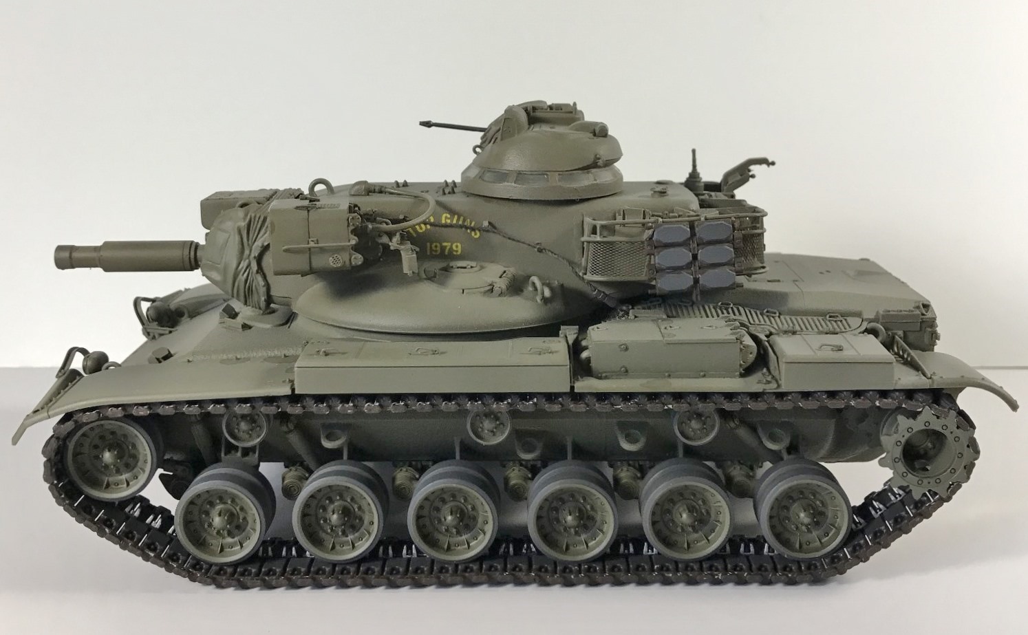
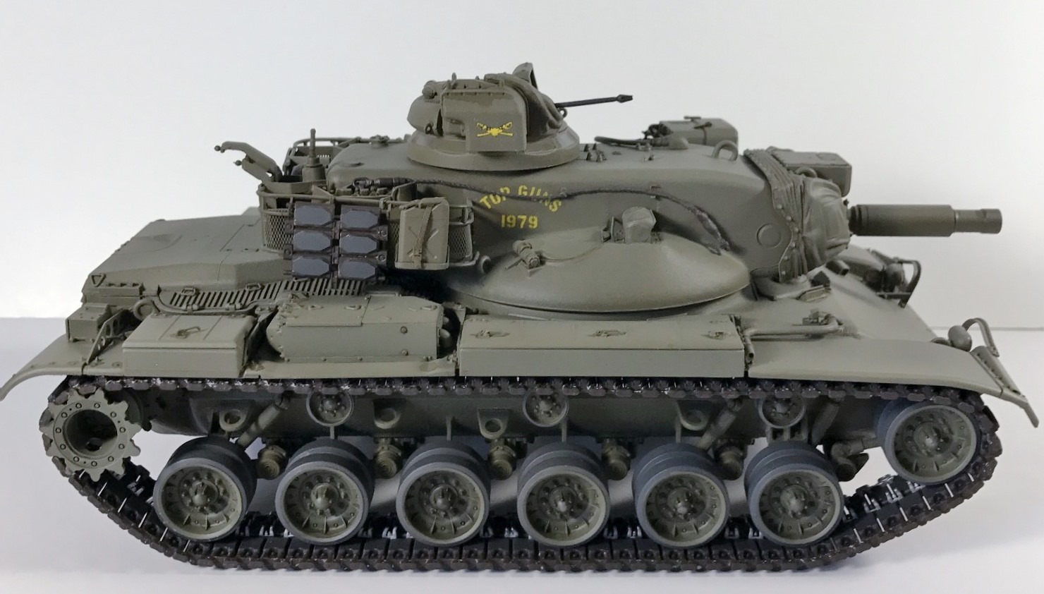
The decals laid down nicely after a clear gloss acrylic coat was applied and allowed to dry for 24 hours. As I usually use Microsol as my setting solution, I found no problem with the supplied decals. After the decals dried for 48 hours, I sprayed on another gloss clear acrylic coat to protect them during the weathering process.
Painting
I sprayed a primer coat on the road wheels, sprockets and rollers using Vallejo USA Olive Drab Surface Primer 73.608 followed by a coat of A. Mig Olive Drab Dark Base 925. After these dried, the rubber on the road wheels and rollers was hand painted with Vallejo Panzer Aces Dark Rubber 306. The tracks were sprayed with Ammo Mig Rubber and Tires. The metal was hand painted with Ammo Mig Steel. Pin washes were applied using various acrylics and oil paints. After a filter coat of Vallejo Desert Dust 76.522 was applied to the entire model, different lighter shades of Vallejo Olive Drab paints were applied to lighten various areas.
The tow cable was first primed with Vallejo Black Primer then a coat of Vallejo Model Color German Camo Black Brown 70.822. After this dried a thinned wash was applied using Vallejo Light Rust 505. Pigments were applied using mixes of Ammo Mig Standard Rust and Vallejo Dark Steel was finally applied wiping with a Q-Tip to burnish.
References
- Doyle, David. M48 Patton: A Visual History of the U.S. Army’s Mid 20th Century Battle Tank. Ampersand Publishing Comp, 2015.
- Doyle, David. M60 Main Battle Tank: In Action. Squadron/Signal Publications, 2017.
- Mesko, Jim. M60 Patton: In Action. Squadron/Signal Publications, 1986.
In Conclusion
After completing each kit, I ask myself, “would I build this kit again?” In regards to this kit, my answer is “most certainly yes”. Due to the combination of different kit sprues, one is left with many parts remaining to add to an extra parts bin. AFV Club does not designate which parts are unused. Detail molded into the kit such as foundry marks and casting numbers on the hull and turret add to a feature of the model.
This was an enjoyable build. I highly recommend this kit, however, due to the complexity, it should be reserved for the intermediate to advanced builders.
Thanks to IPMS/USA and Hobby Fan/AFV Club for allowing me to review this kit.


Reviewer Bio
Phillip Cavender

Phil Cavender, IPMS/USA #50085, is a retired pharmacist from the Veterans Administration, having retired in 2011. While he explored model car building as a child, it wasn’t until 2015 that he rediscovered plastic scale modeling. His renewed interest emerged while researching his father’s military history, which led him to a local hobby shop. There, he met a former UK military tanker who reignited his passion for the hobby. After relocating to Myrtle Beach, Phil teamed up with six skilled modelers to co-found the Grand Strand Scale Modelers chapter of IPMS/USA. He now focuses on building armor models in scales from 1/35th to 1/16th.
Comments
Add new comment
This site is protected by reCAPTCHA and the Google Privacy Policy and Terms of Service apply.
Similar Reviews