
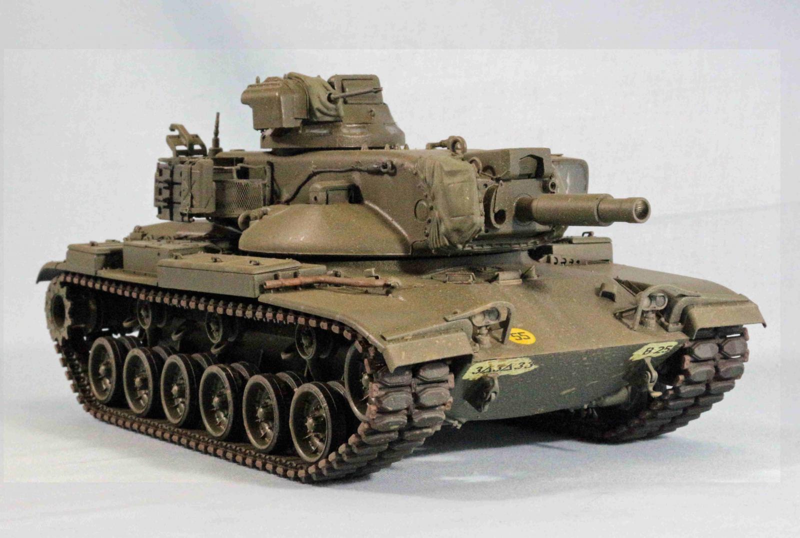
M60A2 Early Type AF35238
Intro
The M60A2 early type by AFV Club is another one of their M60 series of vehicles including the M60A1, M60A3, M60A2Early and later and the M728 CEV as well as several Foreign subjects based on the M60 series of tanks. The M60A2 early includes sprues from the common components of the hull and turret and running gear. M60A2 specific components are included to model the right vehicle. In this case the Gun barrel with the bore evacuator and the M60A2 turret and assemblies.
Background
The ARCOVE report published in January 1958 recommended a major effort be directed toward the development by 1965 of a guided missile weapon system for future main battle tanks. Thus set in motion the development of the Combat Vehicle Weapons System Shillelagh (CVWS) which consisted of the 152mm XM81 gun launcher. This could fire conventional projectiles or the XM13 missile. The conventional projectiles had a completely combustible case and primer. The XM13 Shillelagh missile was ejected from the tank and a solid rocket motor propelled the missile to the target under the infrared line of sight guidance system. Development proceeded during the early 1960’s and in July 1965 the M60A1E1 was type classified and 243 M1A1E1 turrets were procured with 1966 fiscal year funds and an additional 300 tanks were purchased with FY1967 funds. These were later standardized as the 152mm gun Full Tracked Combat Tank M60A2. Army figures show 540 M60A2 tanks produced. The consumable cartridge cases did not completely burn and left hot gasses and residue inside the breech, slowing the loading of subsequent rounds. This was addressed by fitting the closed breech scavenging system (CBSS). This was a high pressure compressed air system that injected 1000PSI air into the breech right after firing to clear the residue. These subsequently modified tanks can be identified by a bulge at the rear of the hull behind the engine and a gun tube without a bore evacuator (straight tube) The M60A2 tank was fielded to Armor units in Europe in 1975. Production was halted in 1975. Due to operational issues with the Missile and the fire control system the tank was phased out of service by 1980 with the rise of the deployment of High velocity Fin stabilized Sabot rounds that could be used by the M60A1 and the M60A3 tanks.
Opening the Box
There were approximately 15 sprues molded in clear, black and olive green plus the metal barrel, decals, vinyl components and tracks. Parts count is over 500
The Instructions
The instructions are a 20 page booklet with a color slick front page and the color slick 4 view schema rear page for the two decal options . There is a Sprue Tree map on page 19 and a notes and colors chart on page 2. There are 39 assembly steps. Discrepancies will be noted in the build notes. There is a separate color box art flyer.
Things to consider before building:
- You will have more parts than required to build the model since many common M60 parts aren’t always used.
- The vinyl components(Main gun and commander machine gun shroud) can be glued with liquid cement, but be careful it will eat the plastic, work slowly and clamp or hold until parts are adhered, or use alternate cements
- Almost all the photo etch is used for the bustle rack bottoms and sides, you will mostly use these for strength during assembly since the tubing is styrene and delicate and difficult to arrange with the bracing. This will be the most difficult part of the assembly process.
- The Searchlight is a kit just by itself, 19 parts and photo etch. It’s about the size of a sugar cube. Slow down for this step.
- In step 4 it shows Part O-1 being glued onto the hull rear underneath. Don’t use this as it is for the late version and houses the CBSS air compressor, which is only needed on the late version of the kit. The towing pintle is also attached to this part, but the regular Tow pintle parts for the M60 tank hull are included (C10, 11, 12, 13) this will have to be fudged, since no drawing is available, but there are locating lines for the pintle arms on the hull. You will have to fill in the locator slots for part O-1. The correct grill doors are on the “C”sprue. C87, 88
The Build
Lower Hull and Suspension
- Steps 1-6 covers everything track and suspension related. It’s very straight forward. Other bits included are the lighting and tow pintle, lifting eyes and bump stops.
- The shocks/snubbers and mounts(C9,D9,C17) need to be snapped together into upper, snubber lower mount first since it will be near impossible to do if you try to snap the snubber into the mounts after you glue them onto the hull and road wheel arm.
- Tow pintle, See above in things to consider.
- The road wheel arm has the torsion bar, which is keyed, molded on it, it will fit inside the mount holes, but the fit is tight, you may want to fit sand it so you don’t break it while inserting it across the hull, Use caution.
- The road wheels have an O-ring sealed between them to retain on the road wheel axle. You might want to wait until after painting as the underside of the tank is pretty busy and the road wheels block painting a lot of that.
Upper Hull and Decks
- Step 7 is the driver’s compartment. If you want that level of detail it is spread across the bottom hull, inside of the forward hull. It is very detailed and the parts are delicate and fragile, I kept breaking thin parts, so I closed it up and moved on.
- The drivers hatch is attached to a torsion bar that is glued onto the bottom side of the deck, it might be able to be just glued into the hole. The drivers vision blocks are pushed up from the inside of the deck, do this before you attach the front deck onto the hull. If you bypass the driver’s compartment, this is easy to forget.
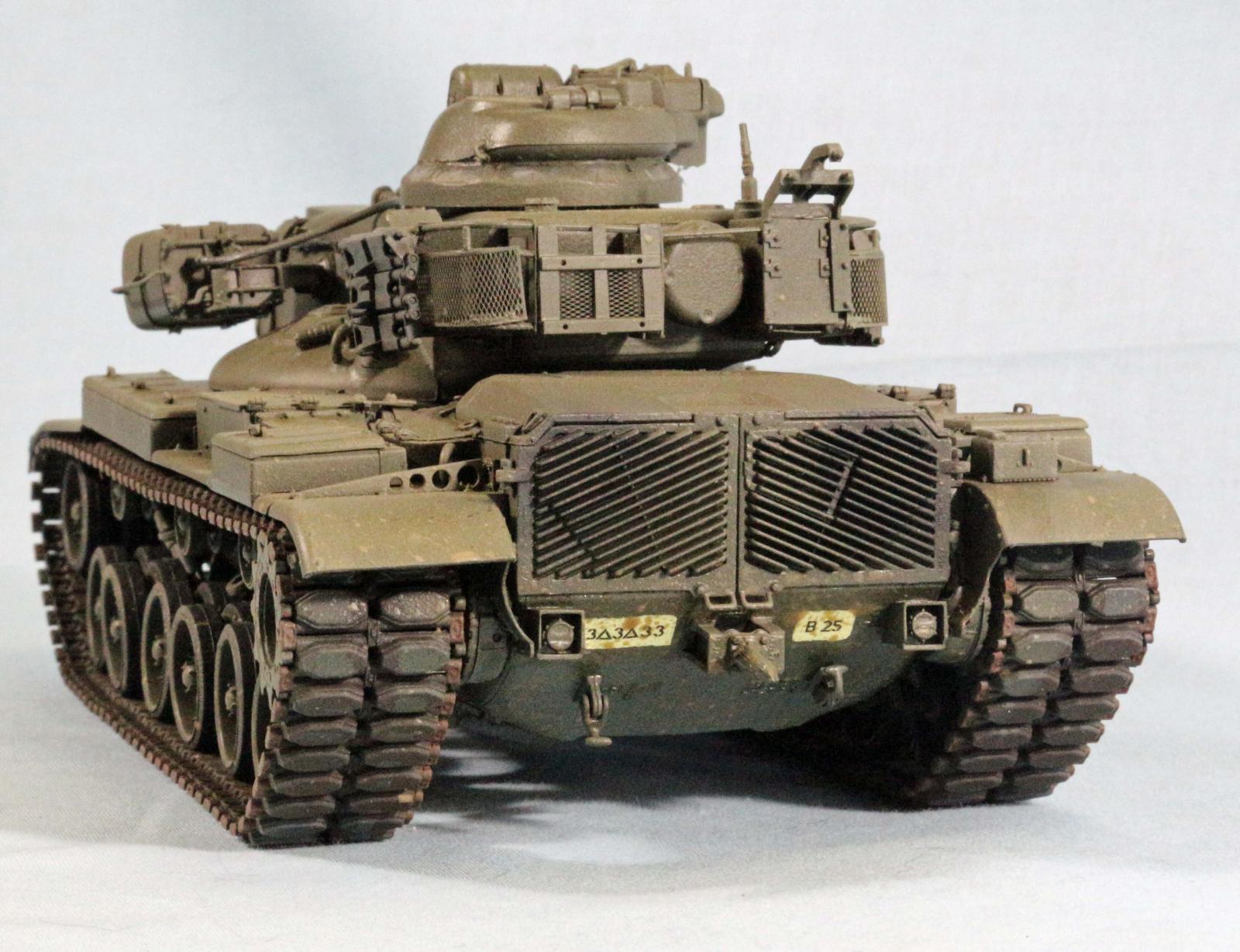
- In step 10 There are the grill door hinges that are on the outside of the hull at the rear (D22Rt Side D23 Lf Side) these are easy to miss so glue the grill doors on first then glue the back deck on to align everything. Do not use the indicated O2, O3 grill doors, use C87, 88 as those are for the earlier version without the Compressor see not in before you build above?
- The grill doors come in two flavors in Step 19, do not use C3, C34, C89 or K1 since those are for the M60A2 fording kit exhaust stack. I have never seen a picture of that fitted. Use C90 and fill the hole on the right rear grill door
- There are 10 top deck access doors that cover the gap between the hull and the back deck. There are triangular and “D” handles that go on the access grill covers, you just glued on. They are small and delicate and easily broken if you don’t use a sharp cutter like a God Hand to trim them from the sprues. Tweezers will fling them everywhere if not careful as well. They really add the detail however so the attention will be rewarded.
- You may have to make a decision on when to put the track on. The instructions show them being applied before the fenders get glued on, you could leave them off if you are careful threading them over the sprockets and connecting them underneath. When in place, they obstruct airbrushing all the bits under the hull between the road wheels and fenders, Builder choice on when to thread the track. The under fender clearance is tight, but workable.
The Tracks
Not much here, the two tracks are some sort of synthetic rubber but it is connected by a pin so you don’t need to glue it or staple it. The section that is pinned can be torn so be careful
The Turret
- The Commander’s cupola is steps 22-24. The turret build up is step 25-27
- The Tow Cable mounting brackets are PE that needs to be bent into a J shape and glued to the turret side, there are locating marks, but they are very light
- The rest of the turret is pretty straightforward, most everything has a good locator or fits well. Lots of bits.
- The Searchlight mounting brackets are fragile, so be careful. I somehow lost the alignment with the gun tube and it appears to point lower than the gun/launch tube. Pay attention during gluing as there is only one glue for the mounting arm and that is where I went wrong.
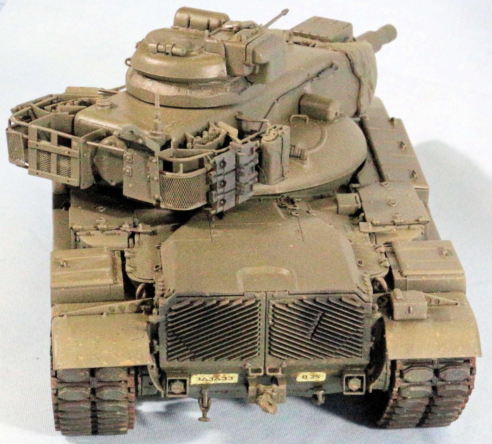
- The monumental struggle I had was with the bustle racks. The PE is a requirement to assist with the assembly to give it structure. The thin tubes are very fragile and are in one piece and have to be threaded through the mounting panels and get all the fiddley bit glued together, you need 5 hands to align and assemble it all. I had to repair everything at least once while trying to attach everything. I wish you all success if you take up this challenge. It looks nice when you get it attached and painted to hide all the glue. I recommend Bondic UV set adhesive to assist.
Painting and Finish
Primer and Pre-Shade
I started by applying a primer consisting of Krylon Color Master with Durable ColorMax Technology rattle can (Flat Black) paint. It has great thin coverage and quick drying time. I left it to dry overnight to make sure it was fully cured.
Airbrushing Mission Models Acrylics
I had to do some soul searching regarding the gloss OD finish. The M60 was developed and fielded during the Army’s transition from Solid Olive Drab finishes. My research showed a lot of dark shade OD solid green tanks. As the MERDEC schemes were standardized, they were used as were some local adaptions. Also during this time, the M60A2 series was being phased out of the inventory, its service life was relatively short. That being said, I went with an OD scheme, I wasn’t happy with the bottled Od as it appeared too green and not dark enough from what I remember of what I have seen, and what I saw in photos. So I settled on a darker shade. I mixed Mission Models MMP 026 US Army Olive Drab FS33070 and darkened it with MMP 035 NATO Black, which had a green tint. I mixed it 7 parts MMP-026 to 3 parts MMP-035 I then top coated it with MMP-008 Gloss Clear Coat
Decals
The decals were fine; they went on easy and adhered no problems. I got in trouble with one decal that was not split across the tow cable and it folded in on itself, so ruined, I left it off.
Details
I went back by hand and painted the heater exhaust pipe on the right fender, the machine gun barrel in the cupola and the end connectors and center guides on the track.
Weathering
I was restrained on the weathering as most of my experience with tanks on European roads was mostly road wash and dust, not much mud, a little European splash mud from Vallejo and some AK Rain marks For NATO tanks. I then hit it with a dusting of Vallejo Model Air 71.027 Light Brown to dust it up and cut the glossiness without covering it over.
Conclusion
This early version of the M60A2 is well represented by the parts mix in this kit, but the instructions will have you build the wrong version with all the parts for the Closed Breech Scavenging System (CBSS) AFV Club produces the later version of that kit that would use that component and is most likely included in that kit as well. The kit parts pretty much have great fit and there are subtle locator marks for the tow cable PE and other parts. This basic chassis is used for multiple M60 Variant kits and has made use of the basic parts with multiple sprues to cover the subtle variants. The only really challenge I had was the bustle rack parts and assembly. Because the plastic components were so delicate and had unusual molding, it was very hard for me to assemble without breaking some of them.
I would like to thank AFV Club for the kit to review and IPMS for the opportunity to review this kit. Thanks for the crew support of the reviewers.


Comments
As fielded in Germany
The A2s fielded in Germany all had the CBSS bulge. The prototypes didn't, and the system was added before the actual service vehicles were constructed. In my battalion, we had 3 types of gun tubes. Plain straight, plain, but with mounting bosses for the bore evacuator, and with the bore evacuator. The vehicles with the bore evacuator, had the interior veturi jets blocked. These tubes were used,until supplies ran out.
On the sides of the lower hull, were either 2 or 4 heavy duty mounting bosses. If you are building an earlier constructed tank, add all 4. Later series hulls, only had 2. My tank, C-23 (1/37 armor) had 2 lugs, BUT the first version of gun tube. Do not worry if the elevation of the searchlight is a bit up or down, there was a switch inside, to allow fine adjustments to be made. If you are building atank in use before late 1976, use the chevron tracks T97. Late 1976 we swapped them for T142 track with replaceable pads.
Add new comment
This site is protected by reCAPTCHA and the Google Privacy Policy and Terms of Service apply.
Similar Reviews